Microcontrollers 13 - Segment LED Multiplexing
Multiplexing is the running of multiple targets simultaneously, such as multiple segment LED displays. One way to control multiple displays would be to use seven output pins for each of the displays, obviously this would greatly limit the amount of displays or would require a large chip, the other method is to use multiplexing. The segments on a display "a-g" are connected to the output pins on a chip, the common terminal is connected to another pin. So for example "Port A" could be used to control the segments, "Port B" could then be used to control eight displays. By turning each of the displays on one by one in sequence fast enough will give the appearance of that the LED's are constantly lit, 25Hz is the minimum speed required for the display, however speeds nearing 200Hz are commonly used. Another thing to consider is the duty cycle of the LED, the more displays the lower the duty cycle of the LED, quite simply the current is increased.
Sometimes the problem with multiplexing is that if there is an interrupt the display will stop, depending how long this interrupt programs runs for, or any delays in a program will also stop the display unless the program loops through the display part of the program, this would make delays inaccurate or hard to calculate. One way to get around all of this is to have two separate chips, one as a master chip with the main program and then a slave chip that is dedicated to running just the display, this is where serial communication will come in handy, especially I2C as explained in the next chapter.
For this chapter I will create a serial number display, so for example I could display the number of measurements remaining for the data logger, note this is just for demonstration purposes as it would be much easier to do this on the LCD. Below is the circuit diagram, note the addition of transistors to control the display, this is due to the microcontroller being limited to 20mA per pin.
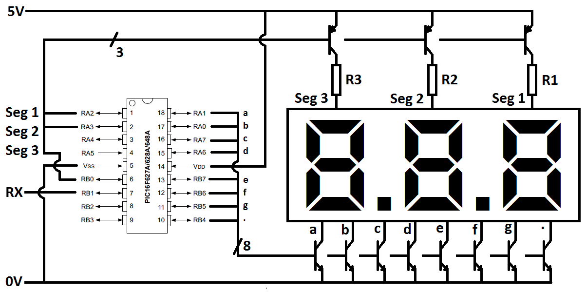
It is better to use MOSFET's rather than transistors which is what I chose as these require less current to switch them on / off, there is also a smaller voltage drop. The LED's will have a voltage drop of around 2.5V when running at 60mA and the transistors would have around 0.7V drop whereas MOSFET's would have around 0.1V drop (2N7000). To calculate the resistor you divide the remaining voltage by the current, so with MOSFET's you would need resistors of 38 ohm.
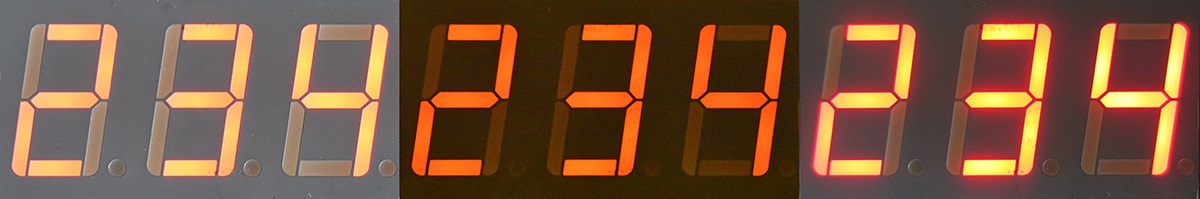
The picture to the far left shows running the circuit with resistors, I used a logic chip to provide the voltage as I didn't have any p-channel MOSFET's at hand. The middle picture is exactly the same, just in darker light conditions, the camera really struggles to pick the light up. The right picture is using no-resistors and n-channel MOSFET's to source the current, not ideal.
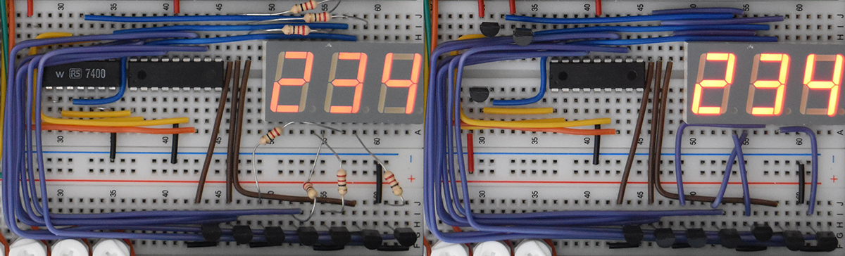
The left shows me using a 7400 chip to provide the positive side, it unfortunately cannot source enough current, hence the dim display. The second picture shows me using n-channel MOSFET's to source the current instead, this is however not ideal so I had to remove the resistors totally to provide enough current.
I'm not going to spend too much time on the above as if you follow the circuit diagram it will run just fine, I didn't have all the right components at the time of writing this to perfect the hardware, however this is just a demonstration of the program.
As for the program, here it is, or you can view it in text format - Common Anode or Common Cathode.
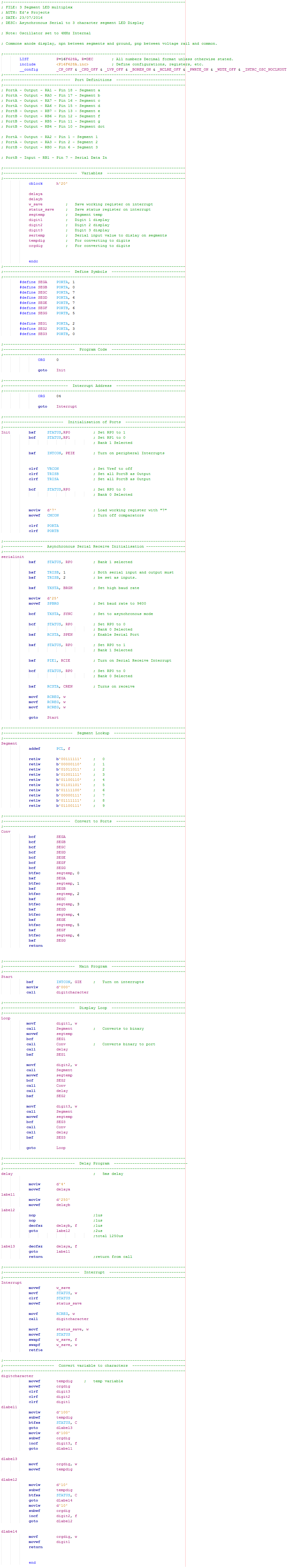
It first sets all of the initialisation procedures such as the port definitions, the serial and the interrupts. The program displays the digits zero and waits until some serial data is received before it changes the display. Whatever is read from the serial port is sent to a program that splits it up into three separate digits. The first digit is sent to a lookup table which breaks it down into binary to match the character on the display, the first segment cluster is powered and then another program converts the binary into outputs. A delay of 5ms is utilised, the segment cluster is turned off and the process begins again for the next two segment clusters. The program continues to loop waiting for serial data to be received, since it uses an interrupt and the program is fast the display does not flicker. The whole display is refreshed at 67Hz which is considered to be adequate, most tv's have a refresh rate of 60Hz (correct at time of writing this).
All that is required from the master chip is a serial signal to show the user the number of measurements remaining. Both of the programs have been updated, the master chip will send out serial data every time the number of measurements variable is decremented. The slave chip has it's received function disabled while reading to stop the register being overloaded, there is an added delay since the readings finish before the master program sends the final byte of data.
Updated programs - Receive - Master
Updated programs - Transmit - Slave
This project was quite an easy one but sometimes people find it quite difficult to run multiple displays, there are other such ways of doing so which is the use of a BCD to 7-segment convert chip, this reduces the seven pins down to four. I however cannot demonstrate this chip (the 4511) due to be segment display being common anode, the alternative would be to use transistors on all the outputs.
The next project is a very important one which makes use of asynchronous serial and the required protocol. Internal EEPROM is rather slow and limited in bytes, the use of external EEPROM with a faster speed is very useful.
Hello, if you have enjoyed reading this project, have taken an interest in another or want me to progress one further then please consider donating or even sponsoring a small amount every month, for more information on why you may like to help me out then follow the sponsor link to the left. Otherwise you can donate any amount with the link below, thank you!