Conversion from Carburettor to EFI
For a long time I have been considering a change of motorbike, but due to my financial commitments and the for-seeable future, I cannot afford to buy one. Instead I will keep with my first proper bike, a Honda Hornet 600 (1998 model). I have chosen to completely restore the whole bike, literally all the paint, bearings, etc... The bike is completely standard except for the paint, so I really want to make it something a little more special. The bike comes with a four bank carb setup, they are already quite refined, so something like an electronic injection setup may only increase power by a couple of BHP and slightly lower the torque band. Nevertheless it will be an interesting project to try and convert, it will also allow for a low-boost turbo in the future.
September 27/09/2014
Today I started this page. I was doing some thinking about making use of a fuel injection pump that I had previously bought for another project, further research and I realised that the pump would be overkill and require too much current to operate (15 Amp). Today I bought myself a different pump that would only require 5A, the bike's alternator should have no problem with this. I have bought an Air-Fuel ratio meter that will bolt to the clocks, a wide-band lambda sensor will connect to the exhaust. This clock will aid with tuning to find the correct stoichiometric ratio, 14.7:1 is what is considered to be the correct value, although 13:1 will yield the most power and keep things running cooler.
When I have got a couple of my projects out of the way, I will then start construction on some injection bodies, then I can start to play. I'm hoping to make a simple ECU that will read the lambda and the compensate by increasing or decreasing fuel, hopefully by logic circuitry, although if all else fail's then I will be purchasing a programmable ECU.
Note: I will not start work on this project until the CNC lathe page has been completed and the nuclear fusion page.
November 30/11/2014
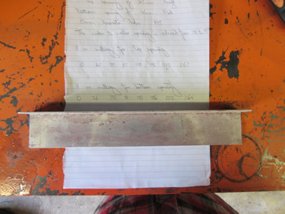
 A month ago I decided that I would not be riding my bike for a while, so instead I thought that it would be time to do the work on it. I welded a lambda sensor to the exhaust and attached the AFR meter next to the clocks. I went on a ride to see exactly what the bike was running at, unfortunately not very well. It should be running at an AFR of between 12 and 13 when hard accelerating, it was only 10, which means it was supplying way too much fuel. Tick-over was 13 which should really be between 14 and 15.
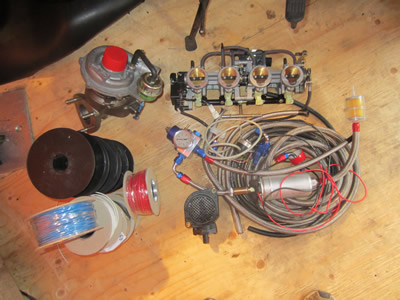
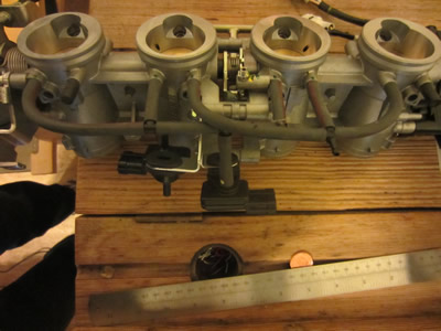
Over the past month I have been buying parts for the bike to convert it to EFI, but making it able to supply enough fuel if I wanted to turbo the bike. I managed to source a throttle body from a zx6r which had 130bhp standard, which is around what I want the turbo to run at. If I increase the fuel pressure from 3 to 3.5 bar then 140bhp will be possible.
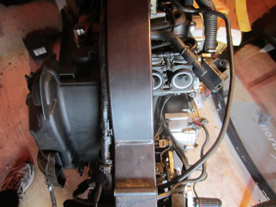
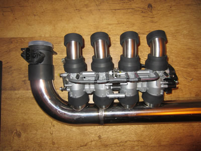
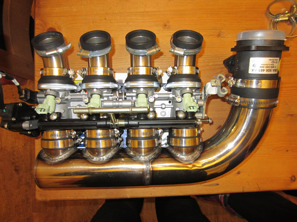
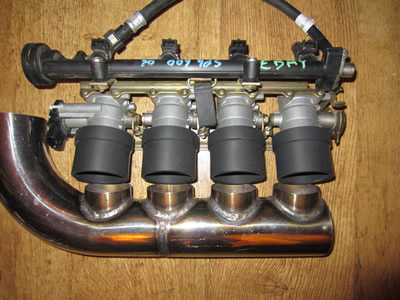
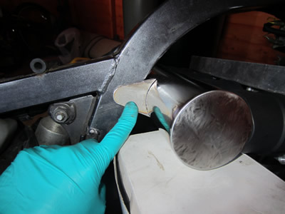
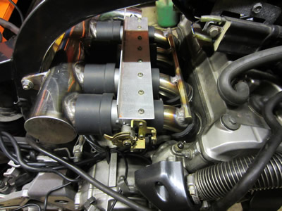
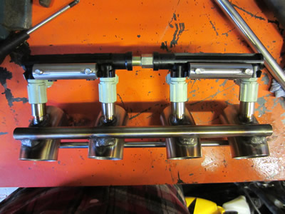
I started to strip down the bike to measure up the space for the throttle bodies and the MAF sensor. I have done this so many times that the process was very quick, although its clear that everything needed a good clean. The right picture shows the fuel system and the turbo. In the past month I spent a lot of time researching fuel injection and turbo calculations, I spent a lot of this writing a calculations page. So, using my calculations I found a suitable turbo that would be most efficient at my calculated boost pressure and power. The turbo I chose also had a three stud manifold, which will make things easier when it comes to welding.
The airbox will no longer be required as it will be replaced by something homemade, it will mean the battery compartment will probably go in the back of the bike. I will also have to make some rubbers for between the engine and the throttle bodies. There should be plenty of room for the MAF sensor, fuel pump, regulator and swirl pot.
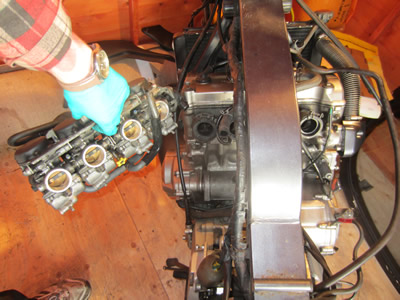
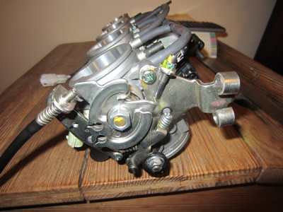
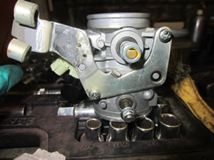
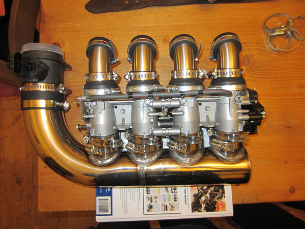
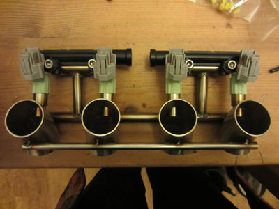
Normally on a throttle body or carb the cable is attached to the right side and the position sensor to the left. Unusually on this body everything seems to be the wrong way around, the injectors are at the bottom and the cable is on the left side pointing up. It means that the cables hit into the tank, this will require some modification. The bodies also come complete with MAP sensors, I removed these as I will be using a MAF sensor instead. Basically a MAP sensor measures the vacuum pressure, the ecu looks up a map and then injects the correct amount of fuel, a turbo setup would make mapping very difficult. A MAF sensor measures the mass of air coming into the engine, the ecu will know how much fuel to inject, when the pressure increases, the mass of the air increases. MAF takes up more room but is better for tuning, the MAP is compact and ok for standard tuning.

The next step is to make some rubbers for between these bodies and the engine, although I'm not sure when I will get the time. I will also make some modifications to the cable assembly, it means grinding and welding. One part that I'm not looking forward to is attaching a cam position sensor, it means welding a peg to the end of one of the cams, machining the cam cover to house a rotary seal and then fixing the sensor itself. I will be removing most of the wiring, changing bulbs to LED and generally making everything else use less power, otherwise I may have to upgrade the alternator and regulator.
December 01/12/2014
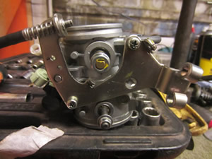
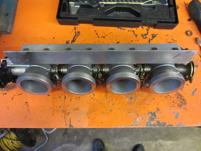
I'm going to do as many parts as I can to the bike through the week, the first being the throttle bodies. They were upside down, so to speak. I did a little bit of chopping and welding, it's surprising how deep galvanising can penetrate into a metal, making welding a little awkward, the TIG allowed me to burn off impurities. I Will give it a lick of paint when its complete, but right now it's not necessary.
December 05/12/2014
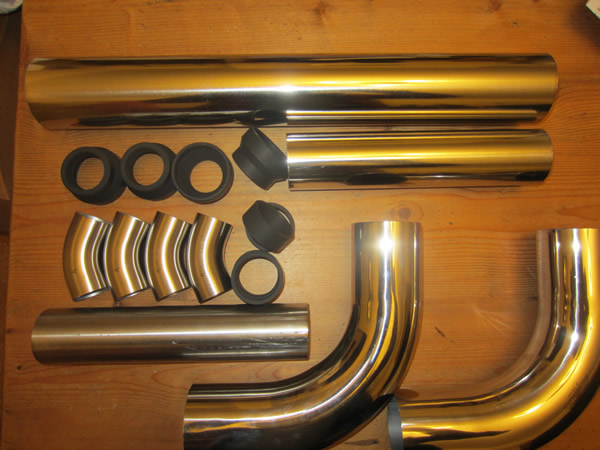
The day after I did the work on the injector bodies I measured up the space for the airbox, I then ordered a load of stainless tube. Aluminium is easy to cut, it's cheap, but quite difficult to weld. Stainless is expensive, hard to machine, but it welds easily and stays shiny. There is very little room for the airbox, so tolerances are quite tight, although it should all fit. The only part that I scared about is the hole notching of the end of the stainless tube and the fact that I have to drill four holes with the saw, after this it should all be plain sailing.
December 06/12/2014
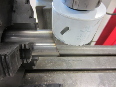
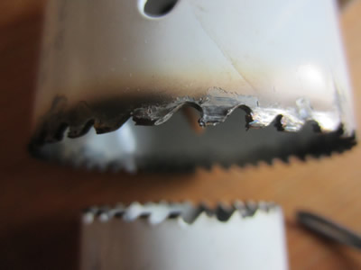
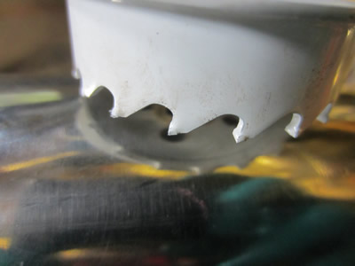
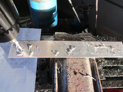
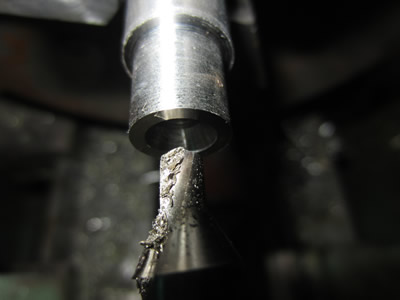
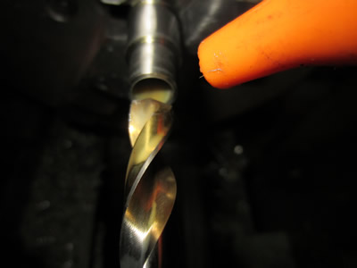
I waited until after I had finished work to commence work on the hole drilling, I have not had a great deal of luck with these hole saw's, but unfortunately I forgot to order a carbide one, so picked these cobalt ones up instead. The first step was to notch some tube, the first one did it perfect, then the second was progressively worse and then the third wouldn't even cut. All I needed was four of these pieces notching, but the cutter was destroyed, so instead I thought that I would drill the holes in the airbox.
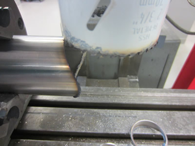
It wasn't a huge surprise that the next set of holes killed the next cutter. I assumed that it was due to the tube being thin and the heat building up quickly, but I used two cups of coolant to keep it cool and it still didn't help. So, defeated, I ordered a carbide hole saw, looks like it's going to be on my miller as I'm off work over the next week.
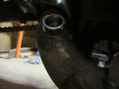
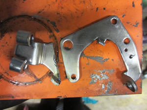
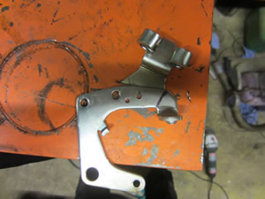
I have been doing a little thinking on the turbo setup, especially the oil pump. Now one of the main problems with turbo-ing a bike is that so much power is needed and simply the alternator cannot supply enough power for an oil pump. On the right side of the engine is a cover for the ignition pick-up, this will be removed as I will be placing a cam position sensor on the camshafts instead. It seems that I have two options, one is to placed a mechanically driven oil pump off this shaft or an alternator, the cam position can then go on here instead, if a timing belt is used. I'm not sure if I can use a ratio of 2: 1 for the oil pump, so I'm leaning towards the alternator, atleast then I will not have to fear of overloading the existing one.
December 07/12/2014
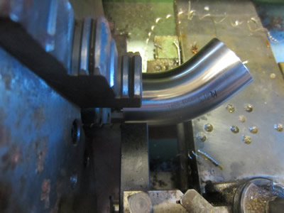
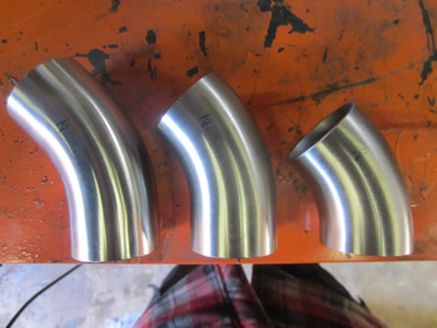
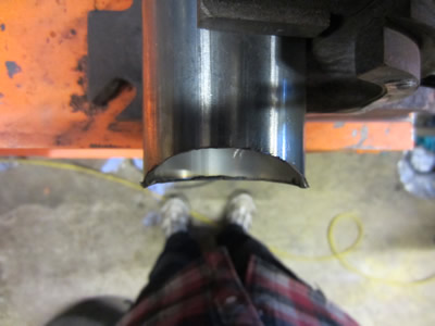
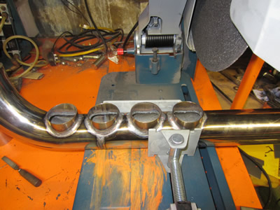
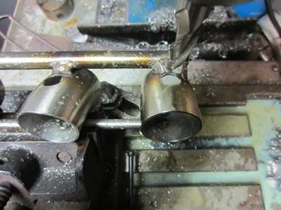
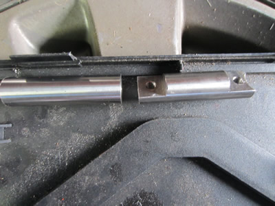
The next step was to cut down the 45° pieces of tube, these are what connect the engine inlets to the injector bodies. I had a really sharp part-off, so I took the risk by clamping the tube alone in the jaws of the lathe, unfortunately this did not work. Soon as the blade broke through the steel it snapped the part-off and ripped out the tube, now too dented to bend back, if I could even bend it.
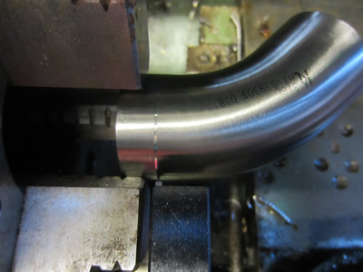
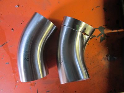
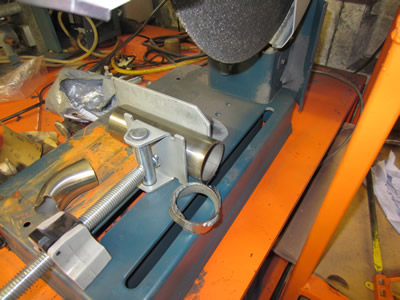
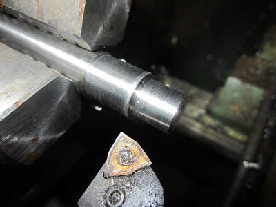
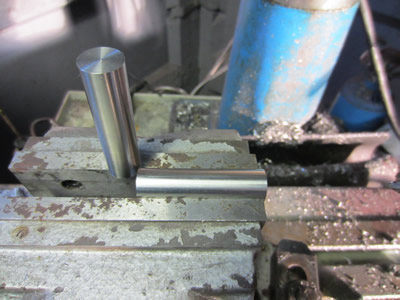
I spent a little time wondering how I could accurately cut a 12mm section off each side of this tube, it's too short to go in the chop saw and the angle grinder is no where near accurate enough. Instead I had the idea of making a steel insert and using the same method to chop the tube down with a part-off. Luckily I had some 35mm sliver steel, the bore of the tube 34.7mm, so I machined a piece and cut it with the chop saw.

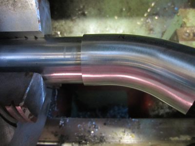
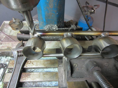
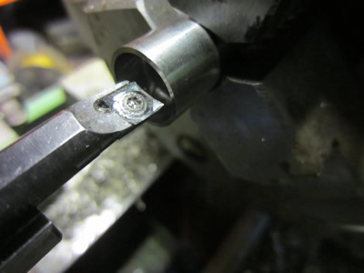
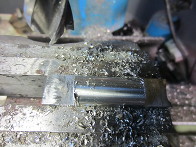
It took an eternity to cut the bar, then the little offcut boiled in water for a few minutes, I imagine that it would have case hardened the bar, but I faced it quite easily. I placed the insert in the tube, tightened it a lot more than I could have previously. The first cut broke the part-off as soon as it made it through, so for the rest I used a much thicker part-off as shown in the pictures below, there was no issue.


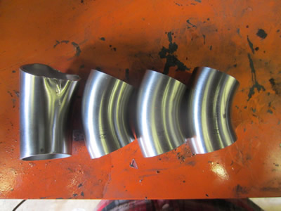
Progressively I cut all of the tubes down to size, they are all now identical. I have ordered another piece of tube for the one that I scrapped, I have also left the lathe setup as delivery should only be a couple of days. I made some measurements and calculations which led me to have 90mm between the injector bodies and the backbone of the frame. I placed the setup on the engine and gave it a measure, 90mm, meaning that it should all fit.

I was hoping that I would have all of this on the bike by now, but I suppose it can be expected when everything is so customised. I need to order a total of 26 hose clips, an alternator, timing belt, pulleys, bearings, some electronic's and then hopefully the bike should be running on EFI.
December 10/12/2014
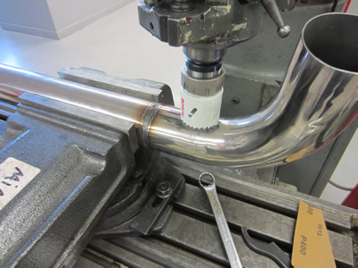
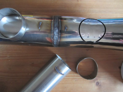
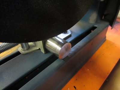
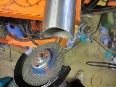
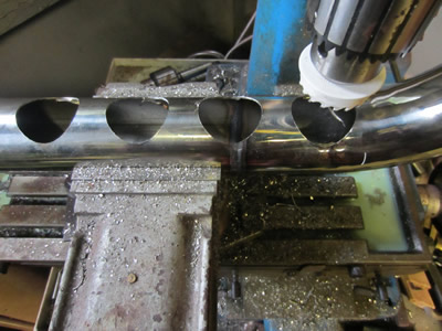
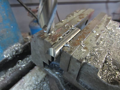
I have a total of five days off from work, so I'm hoping to get quite a way with the bike. I received the stainless bend through the post, a replacement of the one that I scrapped. I machined the elbow down to the required length and then ground all of the corners so they fit in the rubber manifold's easily. I have also received the electronics to make the ECU, this will be started soon, but I'm not exactly sure when. I'm expecting the 51mm hole saw through the post to make the holes in the airbox, in the meantime I thought I should make the notched tubes, these used a 70mm hole saw. I was not willing to spend any more money on a hole saw as the one I required would be rather expensive, instead I gave it a go on the miller. Unfortunately I was not able to clamp the tube properly and it kept moving in the vice, so I had to resort to the angle grinder.
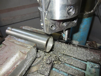
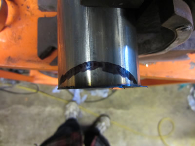
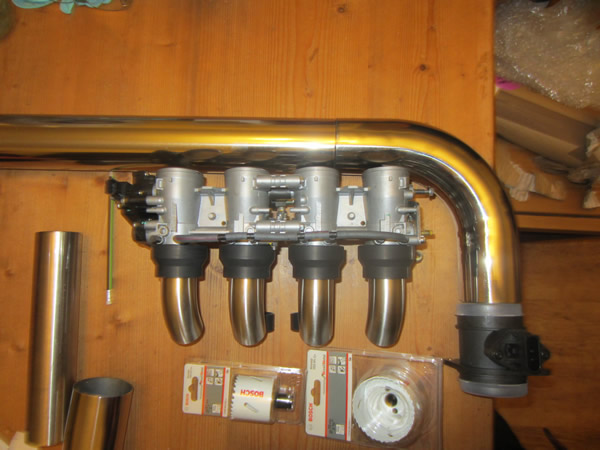
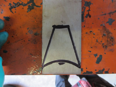
It took me quite a bit of time to get the right contour, but I managed to get it somewhat right, it doesn't have to be perfect as it will be welded afterall. I cut the section on the chop saw and then gave everything a good file to remove all of the burrs, they are now ready to weld to the airbox. To picture to the right gives a representation of the setup.
December 11/12/2014
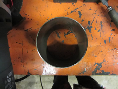
I got my hole saw through the post, it's a carbide tipped one and it only cost me £9, all it needed was an arbor. I managed to unscrew one from a scrapped saw and screwed it into this one. I placed the tube in the vice and could only clamp it gently, I was a little bit nervous as I've not had a great deal of luck in the past, but the saw cut perfectly. I filed the edges of the holes and prepared it for welding.
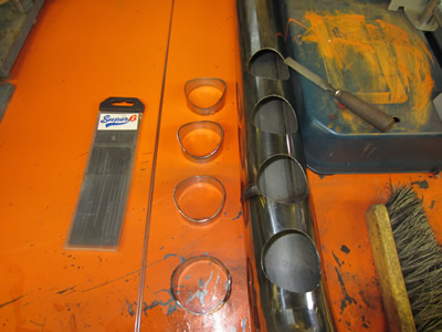
I managed to weld two of the notched tubes before I ran out of shielding gas, so I picked some up along with a load of holes clips for the rubber manifolds. I continued to weld the tubes and cut the remaining tube off in the chop saw.
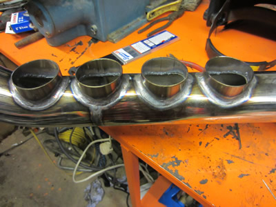
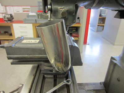
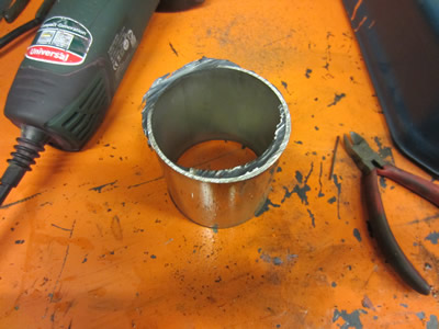
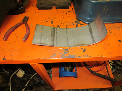
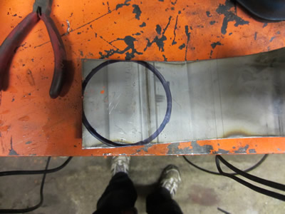
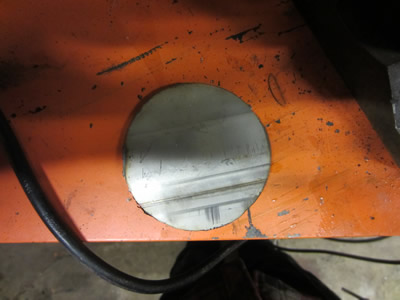
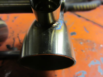
I then needed to make an endcap for the airbox, I had no sheet so instead made it from a piece of tube.
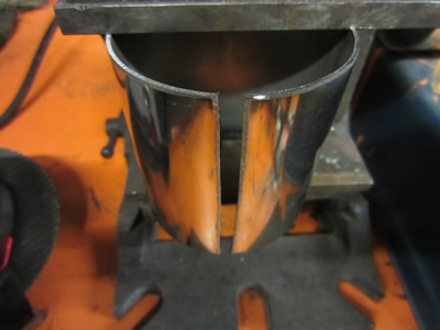

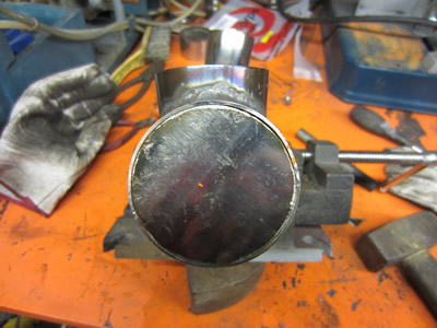
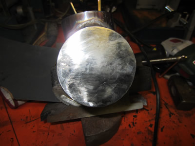
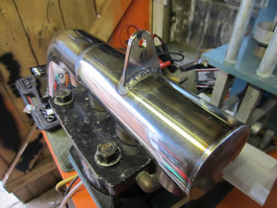
Overall I'm really happy with the way the airbox has turned out, as shown below, I put the hose clips to good use.
December 13/12/2014
I tried to fit the above setup to the bike, I knew it would be close, infact it's about 5mm too long. The big problem is that between the airbox and the injector bodies is a round pipe to an oval shaped pipe. The problem being that the oval on the injector bodies is just too big. I have done a real lot of searching and it looks like the injector bodies from a triumph daytona may be suitable, I'm just waiting for a reply off a seller. If they are not then I will have to modify these bodies, although I cannot weld them as I cannot remove the butterflies, they will have to be bonded, which I'm not too confident about. The only reason I started this project was because I was waiting to buy a car off someone to turbo, I was expecting around February time, but I've bought it early. I want to do the car a lot more than the bike, but the bike has been started, so it will be finished, the EFI part, not necessarily turbo.
The big problem is the oil feed for the turbo, it's a journal bearing type which requires a decent amount of pressure. I've had a couple of idea's but they're too much messing for a bike I'm going to do 500 miles a year on. Instead I'm going to tap the oil output from the oil pressure switch, connect it to the turbo and see if the pressure drops at all. Normally an oil pump reaches a maximum pressure of about 80 psi, but it's flow rate continues to increase. If the pressure does not decrease then it means I'm ok, if it does decrease then it could mean the rest of the engine is not lubricated properly and may fail.
December 31/12/2014
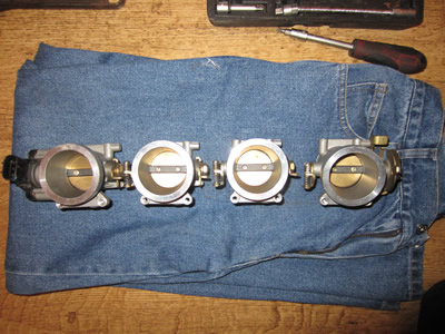
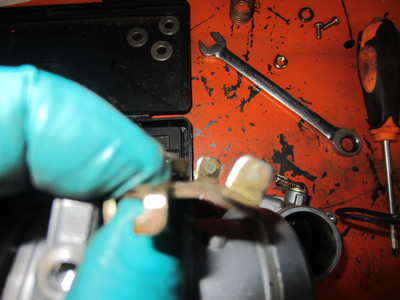
I have finally got around to the injector bodies, the centre spacing on the bodies are 78mm whereas I made the airbox at 75mm, a total of 9mm which is simply too much. Luckily the bodies are modular and can be removed separately, I have to remove a total of 3mm between the linkages below, not easy considering that there is only a mm gap to begin with.
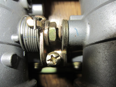
The first step was to dismantle the bodies, I figured that removing 3mm should be possible but 2mm would be ok if not. I started by using a piece of aluminium angle and drilled it out on the miller with the correct spacing, I chose angle as it is quite rigid and will not bend easily.
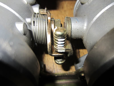
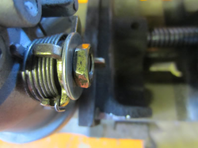
I managed to bend a piece of the linkage, ground down the centre shaft, removed the lock washer and then used a thread lock resin.
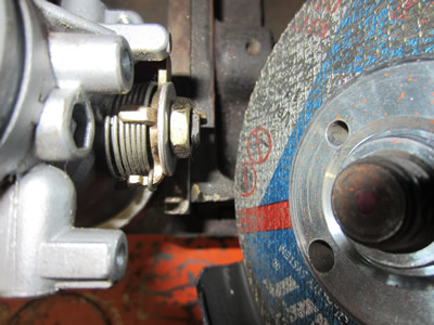
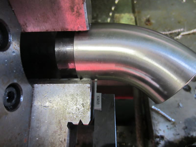
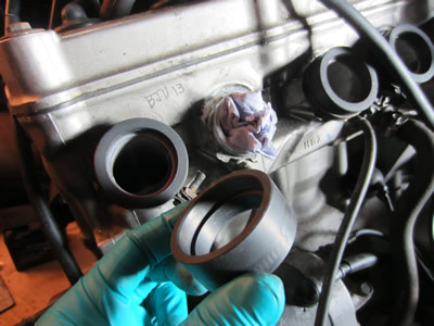
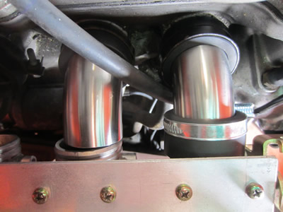
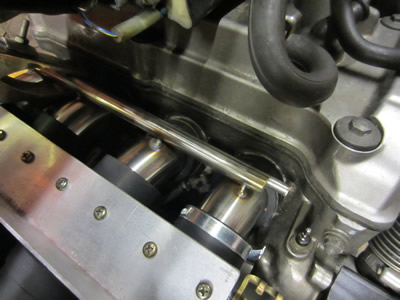
I bolted it all together and it only just fit, so thankfully everything is the correct size now, maybe not. The inlet spacing on the engine was unusual that the gap in the centre was larger, this is probably due to a previous engine design having a centre cam chain. It only required me to grind a slight flat on the end of the elbow and twist it slightly.
I then needed some way of attaching the airbox to the bike, so I made a bracket out of stainless. It did require me to drill a hole through the frame, I'm not too fussed, although I want to make as few modifications to the bike as I can, just so that off the shelf parts will fit and don't require any modification.
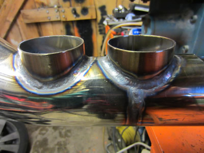
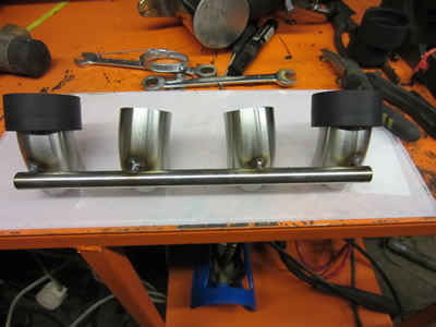
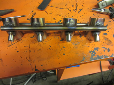
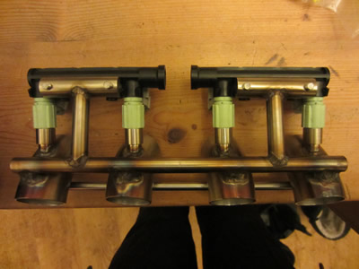
Now the injectors are going to have to go into these elbows, so I needed to make the whole thing rigid. I first tack welded a bar in place along the top of the elbows, removed the whole thing and then tack welded a bar underneath to stop it all twisting when I welded it further (not shown in pictures). I then gave it all a good weld, luckily nothing distorted.
January 03/01/2015
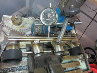
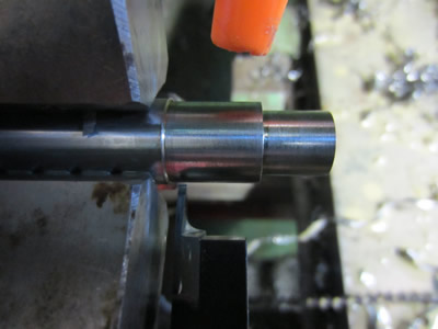
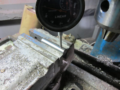
It's about time that I fitted the injectors, so firstly I put the elbow's into the miller using a tilting vice. I used a clock to make sure that the vice was parallel with the bed. Then using progressively larger milling cutters I made a final hole diameter of 12mm in each of the elbow's.
The next step was to make some inserts to house the injectors.
They were quite an easy task, but I'm glad there was only four of them.
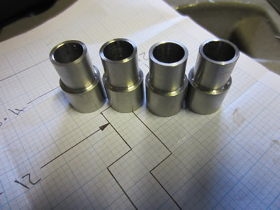
Due to them being thin I had to make sure that the fit was tight otherwise I would have to use a filler rod which could cause things to distort. They weren't too bad to weld, but due to them being at an angle I couldn't quite weld underneath them, so instead these will be sealed with some kind of resin.

January 04/01/2015
Time to fit the injectors. I started by making some brackets to fit to the fuel rail, I cut two pieces of stainless, milled some flats and had a lucky escape with a chuck. The chucks have an arbor pressed into them and sometimes they come loose, so this time I welded it in place.
I drilled a hole in both sides and tapped it to M6. I screwed the parts to the fuel rail and measured up some supports. These were cut to length and then notched with the miller, I wanted a precise fit to avoid using filler rod.
I welded these supports in place.

Hello, if you have enjoyed reading this project, have taken an interest in another or want me to progress one further then please consider donating or even sponsoring a small amount every month, for more information on why you may like to help me out then follow the sponsor link to the left. Otherwise you can donate any amount with the link below, thank you!