Honda Hornet Injection Conversion
January 10/01/2015
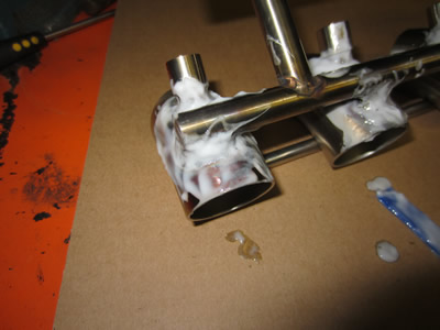
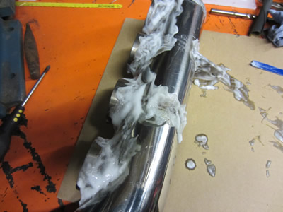
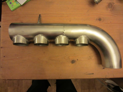
I have encountered a little problem called "sugaring", it's when a surface is welded and oxides build up on the other side, it is caused by excessive heat but can be cured by purging the other side with a shielding gas. I couldn't do this, so had to let it happen. I had heard of something called pickling paste, basically a strong acid such as hydrofluoric which removes oxides, basically the top layer of stainless. I thought that I could use it to remove the some of the boils of oxide that have appeared, it didn't quite work but made a very good job of removing the discolouration from welding. I also used a special epoxy resin to fill in the gaps where I couldn't weld, it's petrol and heat proof so should be ok.
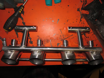
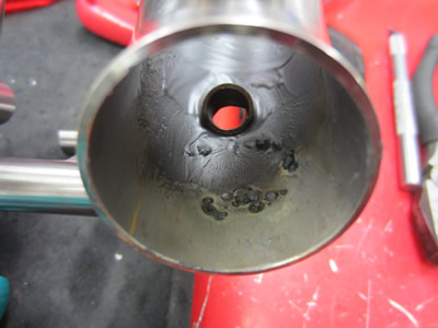
I grinded away the oxide boils, which actually turned out to be stainless, hence the pickling paste not removing them. I also sanded away the epoxy to make the ports smooth, but not polished, the fuel needs somewhere to stick to reduce friction, polishing will cause a slight loss in efficiency.
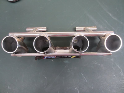
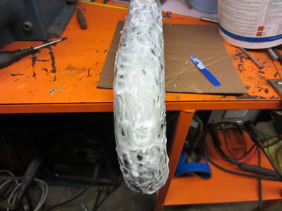
I used the pickling paste on the airbox to remove the discolouration around the welds, I did the whole thing to make it consistently dull, cured by a slight polish, but not a mirror polish.
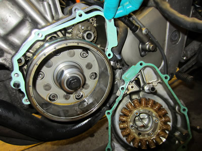
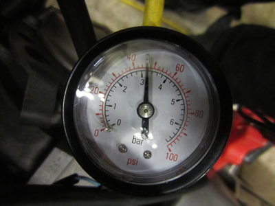
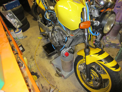
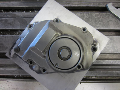
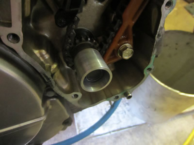
I have been doing a lot of thinking about the turbo, it's not a question of if, but when. The main problem I have is the oil supply, so first I need to see if the oil supply from the bike alone is enough to supply the turbo. I have one output shaft on the bike to run the timing sensor and/or an oil pump, so I need to test the oil pump before I can sort out the timing. I damaged the alternator gasket removing the cover a while back, I replaced it and gave the bike a full service. I removed the oil light pressure switch, connected up a gauge and the switch to the port.
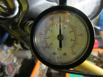
I started the bike to see what the idle oil pressure was, the minimum revs for a pressure of 60psi and the minimum pressure for the oil switch to click off. I have always left the bike to tick over at about 800rpm which turns out to be an oil pressure of 22psi, I turned it up to the recommended 1300rpm which turns out to be 43psi. The bike reaches 60psi at 2500rpm which is a lot lower than expected, a good thing. I turned the bike over on the started motor to see when the oil pressure switched kicked in, turns out that it's only 8psi. Now the plan is to keep this setup and install it to the handle bars, the other step is to install another pressure gauge for the turbo which will be connected to a port located off the oil filter, straight from the pump. Now if the oil pressure remains near 20psi (engine port) at idle then I should be ok, and so long the pressure moves up to 60psi at 3500rpm then all should be good.
January 11/01/2015
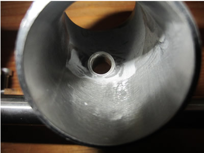
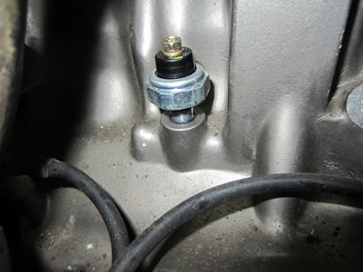
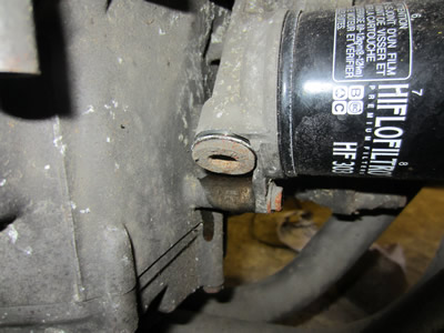
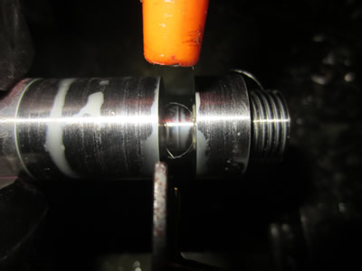
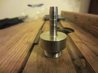
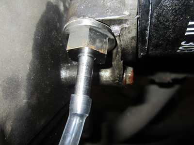
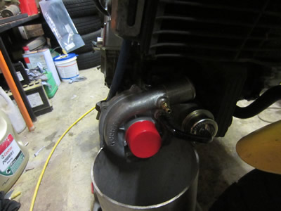
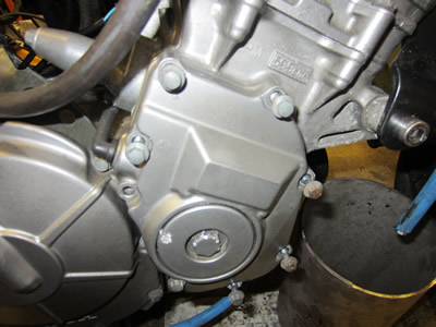
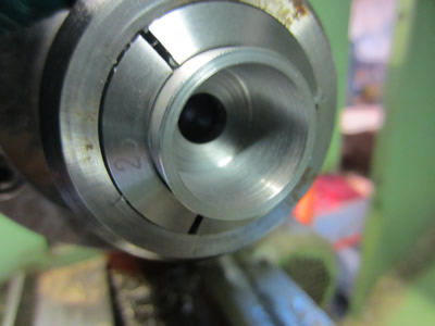
The first picture shows a blanking plug, it is after the oil filter which means that it can be used, the plan is to connect the turbo to this as it's straight from the pump, if there is minimal pressure drop on the gauge at the other end, then all is good. I thought it be best to make the barb from stainless, less chance of me breaking it when tightening.
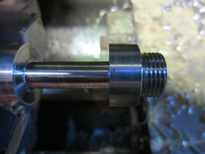
I made the thread to the top end of the ISO tolerance, it didn't screw all of the way, so I put it back in the lathe and took a little more off. I machined on the barbs, all I need to do is machine on a hex. There was no point in me rushing anything as I need some oil pipe, this has been ordered. I have done some thinking about the oil return, generally a turbo is located above the sump and the oil drains through gravity. I can't really see it mattering that the return will be level if I locate the turbo under the swinging arm, if it does, then I will have to put the turbo at the front of the bike and make a whole new manifold. Apparently the problem is the back pressure pushing oil through the compressor side of the turbo, I will have to look out for this.
January 14/01/2015
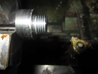
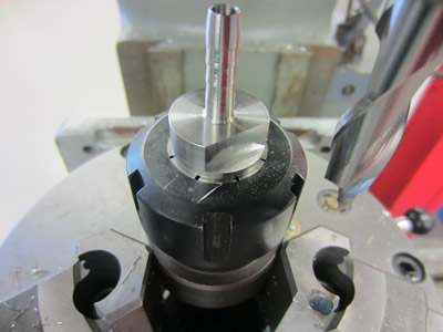
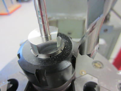
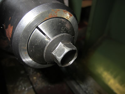
I milled on a hex to the common size of 17mm, stainless can be so nice to machine.
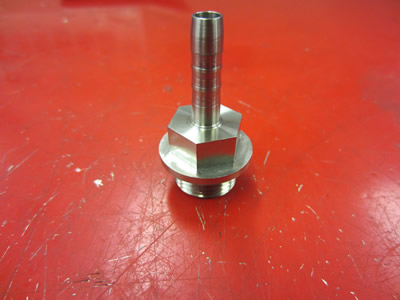
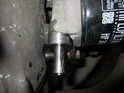
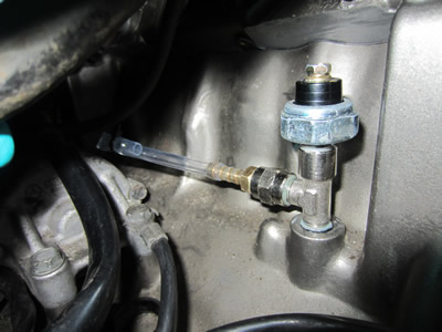
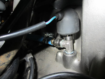
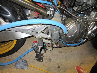
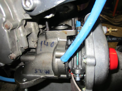
I installed the hose barb to the oil port, I also installed a T-piece to where the pressure switch was located, allowing me to add the oil pipe for the pressure gauge. I used a thread sealing compound, I also used hose clips as a precaution with the hose, apparently the pressure holds the hose in place.
January 16/01/2015
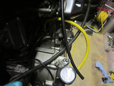
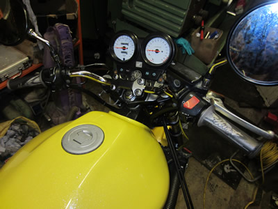
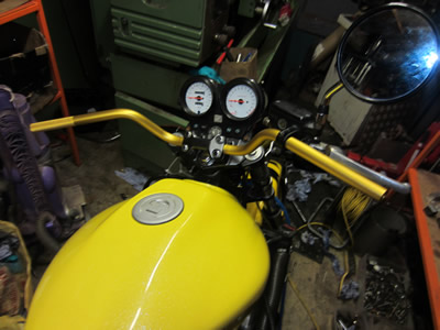
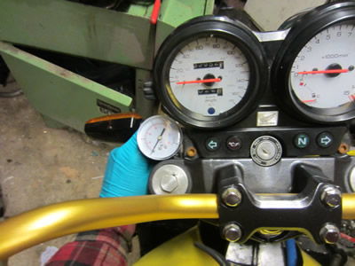
At the front of the bike I want to display some gauges, one being the engine pressure and one being the turbo oil pressure. I thought that it would be time to replace my current handle bars with some high renthal bars, it will also make the bike easier to handle when it wheelie's. I changed the handle bars to get an idea where all of the gauges are going, the oil ones being located next to the top of the fork stanchions. I then proceeded with fitting all of the oil pipes, a little longer than necessary incase I have to relocate anything. I also left the turbo return hose a metre long, it will eventually be around half of this.
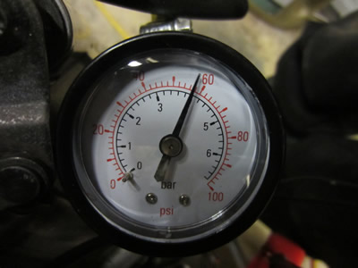
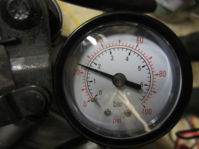
I started up the bike to get an idea of how much pressure drop I will get from the turbo. The bike runs at about 50psi, 1800rpm cold. It went down to 20psi, 1300rpm when hot. The idle will be set around the 1800rpm mark. I opened up the flow valve leading to the turbo all of the way, pressure did not drop at all and flow was quite low. I expect the flow to increase as the turbo heats up, so I will leave the bike running for a while and let the oil circulate, but I think that it's looking good for the oil pump and I shouldn't need to install another one.


I will run the bike again tomorrow and let the oil circulate, probably letting the engine temperature get a little high to ensure at worst case scenario that the oil pressure won't drop too low. If all is good then I will proceed to weld up the turbo.
January 17/01/2015
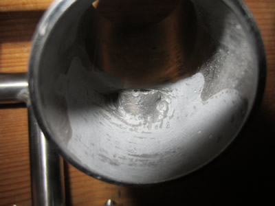
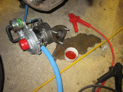 Ok, so I'm rather frustrated, as shown in the picture. Due to the turbo being low mounted the oil has leaked past the seals, I never realised turbo's didn't have seals as such. I knew the oil drain had to have no restrictions, but it must also be gravity drained. I don't have the room for a scavenge pump which means the turbo must be above the sump, very difficult. There is no room at the front of the bike due to the very awkward radiator and oil cooler built into the front of the engine. There is no room at the side due to the awkwardly positioned turbo flanges. It means that I have to use a rear mounted system, It seems that I'm just going to have to go for it and hope the bike looks ok. One major problem could be turbo lag due to the length of the intercooler pipes, although I can put a valve in that allows the intake to draw air from the atmosphere when not in boost, therefore no lag.
January 20/01/2015
I have finally decided that I cannot mount the turbo anywhere else except for at the front underneath the bike, it means that I will need a scavenge pump. Luckily the pump will not need to pump much pressure and neither does the flow need to be high, so current draw should be low. There is just enough room, it means that I will have to make a complete exhaust system including the headers, not a lot of room. The good thing is that the compressor is pointing the right way for the intercooler and then the MAF sensor. There seems to be a lot of work ahead.
February 22/02/2015
I think that I may have become a little too involved with the turbo, It's not necessary as I now know that the oil pump is capable of supplying it, it is now the last thing on the agenda. For now I will put back on the exhaust pipe, and work on the rest of the bike.
The sensor for the ignition and injection system will be the next thing to accomplish, along with the front brakes and the handle bars. The sensor for the timing system is an optical encoder, it will need to be geared to a ratio of 2:1 from the crank, this will replicate the cam shaft position. It will mean removing the original segmented disc and modifying the engine case to accommodate the sensor, a chip will then have to translate this signal into the segmented pulse for the ECU to recognise. I still want to keep the original ECU until I get the injection working, it's one less thing to worry about.
February 23/02/2015
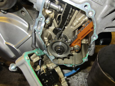
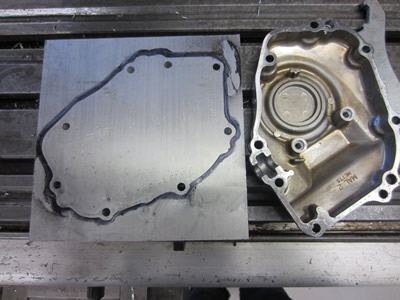
After work I spent a little time in my garage measuring things up for the bike. The first on the list were the brake lines, these are only 10mm short, but I'm going to order some that are 50mm longer to allow for a little room. The next on the list was the pressure gauges for the internal oil pressure and the turbo oil pressure. I measured it all up, did a little bit of designing and purchased some aluminium tube in which I will machine to make some housings for these gauges, they will be located near the top of the yoke as shown in the picture to the left. I removed the timing cover to get an idea of what I need to do, welding was an option, but I will start from scratch instead. I purchased a 20mm piece of plate aluminium in which I will machine from scratch to make a new cover that will house the encoder, I bought some timing pulleys and belts. I also decided that I would make a completely new ignition system, I purchased a coil driving module. I will be removing all of the wiring harness, the ECU, everything, to make myself a completely new one, keeping the old one just incase.
February 27/02/2015
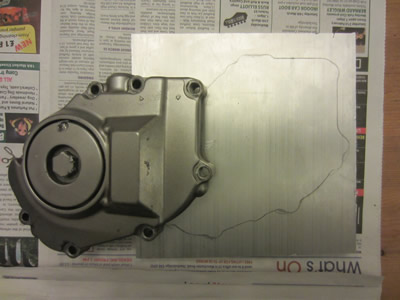
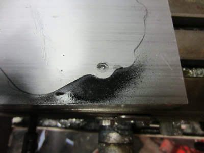
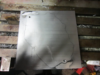
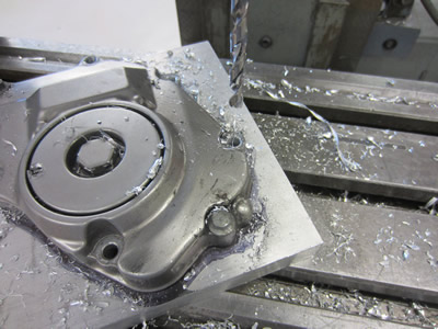
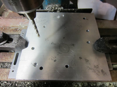
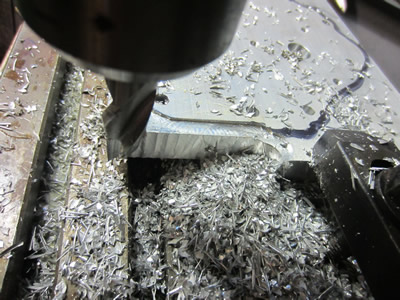
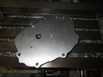
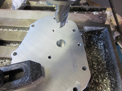
I have received a piece of aluminium plate in which I will make a new timing cover to house the new sensor. I first used the existing cover to make a template, then I sprayed some paint over two of the holes opposite each other. The circles were then centre punched, drilled and tapped to M6.
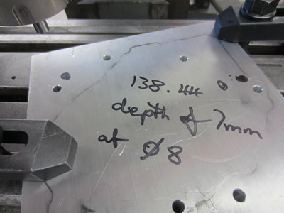
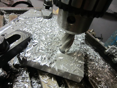
I bolted down the existing cover to the new plate, I then proceeded to use the holes as guides to drill the new holes.
The bolts were removed to drill the remaining holes, one at a time. I did expect the last hole to move slightly, but it didn't, so now all the holes exactly match the pattern of the cover.
There are two locating pegs, these were machined last in the miller, using the digital readouts to get the precise distance between the holes.


February 28/02/2015
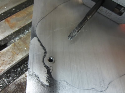
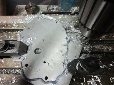
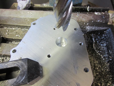
I gave it my best attempt to measure the position of the crank on where is aligns to this case, I then gave my best attempt to drill the hole accurately at this position. The four holes are for the crank position sensor, I have designed the whole thing so that If I haven't managed to get the crank central to the centre hole, then the sensor can be positioned to suit.
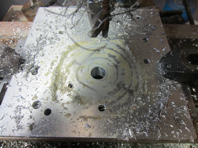
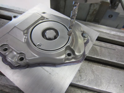
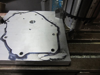
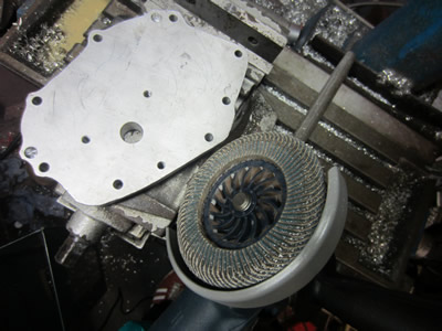
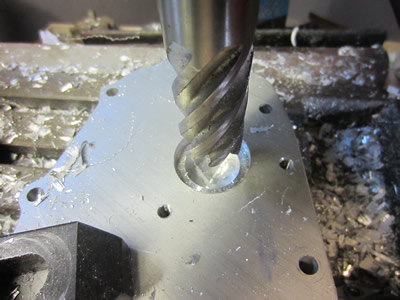
Once the holes were complete I then proceeded to mill out the plate matching the contour of the existing case. I drew an outline with a marker pen and painstakingly milled the excess material away.

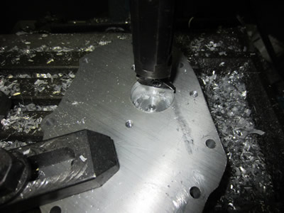
Further milling, it did take quite a while.
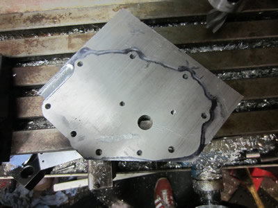
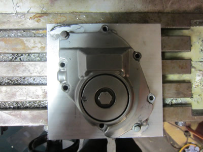
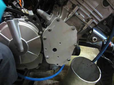
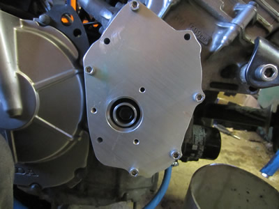
I finally finished off the milling and then finished the edges with a grinder. I fitted the case to the bike, the cover hole is a little offset, but well within the tolerances of my design. The pegs for the case were also a little bit of guess work, but it fit and all of the holes aligned perfectly.
March 07/03/2015
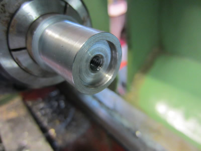
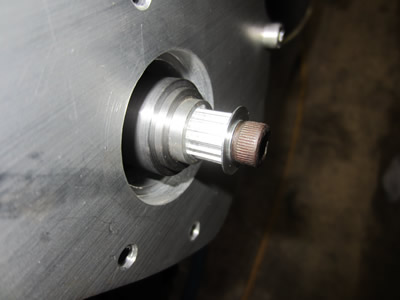
The first part to make was an adapter sleeve to go on the end of the crankshaft, it was made from just mild steel as its quite easy to turn. The outside was turned to a round number, the bore to suit the bolt and the step to suit the end of the crank. The end of the crank measured 19.78, so the step was made to this exact measurement to ensure that it would all be concentric.
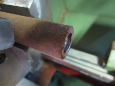
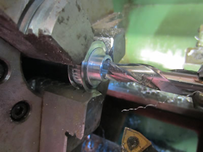
This piece was then parted off and placed in a collet chuck. The back was then faced, drilled and bored to suit the bolt.
The bolt was then placed in the lathe so I could turn down the washer, just small enough so that it would fit down the sleeve.

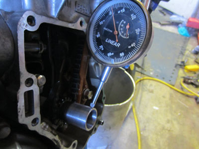
I placed a clock against the sleeve on the engine to ensure that it was concentric, I was quite surprised to find that there was a total of 0.08mm run out, this means that the end of the crank is slightly out, although it doesn't surprise me too much as the end of the crank is broached.
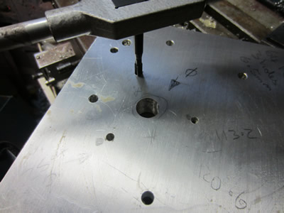
I clamped the engine cover back in the miller, drilled and milled the shaft hole a little bigger. I placed the cover on the engine to get an idea of how things are, the shaft is actually offset by 1mm to the hole in the cover, my design has allowed for this discrepancy. The only thing I didn't expect was the engine cover face not being perpendicular to the crank, which along with the slight offset in the crank has made things rather awkward, I may have to change my design.
There is a rotary seal between encoder and the shaft that stops oil from seeping past the bearings in the sensor, as they are only metal dust seals. The problem is that I now need a little flexibility in the shaft, it either means a polyurethane shaft with a built in metal ring for the rotary seal, or it means replacing the bearing in the encoder with a rubber sealed one, or it could be that I use a polyurethane shaft with the rotary seal running against the sleeve instead.
March 08/03/2015
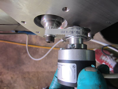
I spent quite a bit of time thinking of what design to use, I realised that a rotary seal wouldn't last very long, even if it were to be made from PTFE, it is due to the shaft not being concentric. In the end I have opted to go for the timing pulley idea as it tolerates a high degree of inaccuracy. I first made an insert to fit into the crank sleeve that I made yesterday, I drilled out a pulley and bolted it in placed using a thread locking agent.
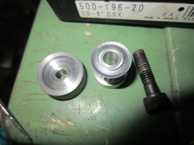
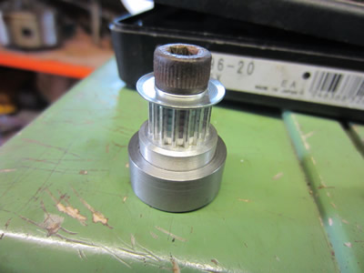
I placed it in the end of the crank, it now just requires a grub screw to lock it into placed, it will also allow me access to the main bolt if necessary. I drilled out the other pulley, made a shaft and assembled it to the encoder. I'm considering making the rest out of perspex, it's easy to machine and it should look pretty interesting.
March 09/03/2015
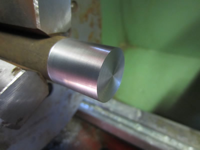
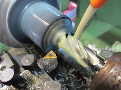
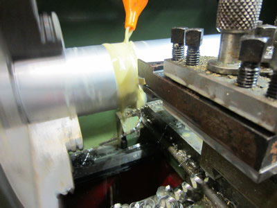
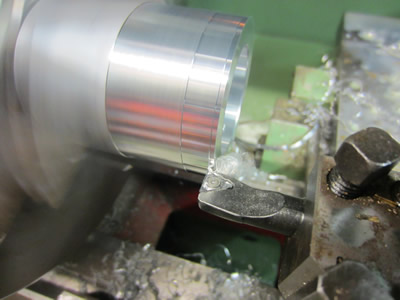
I bought some aluminium tube a while back to make some housings for the gauges. I first started out by cutting the tube into various lengths, making use of the parting tool in the lathe.
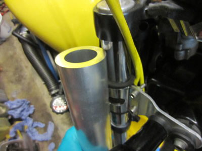
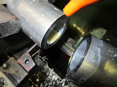
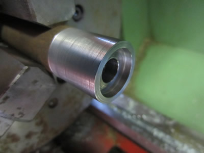
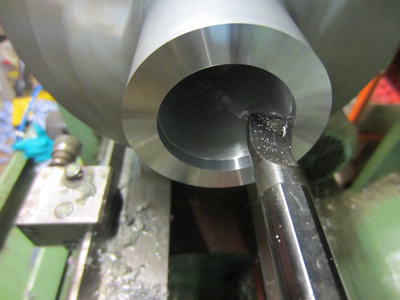
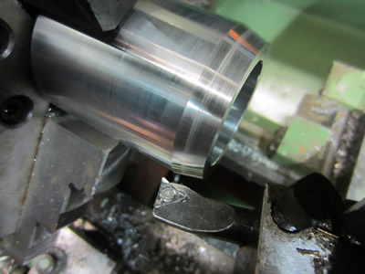
All of the tubes were cut, I then proceeded to facing, boring and then turning the outside.
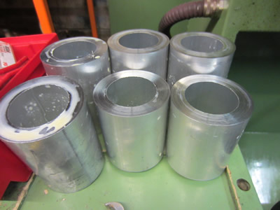
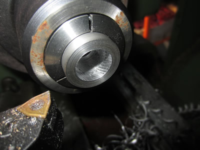
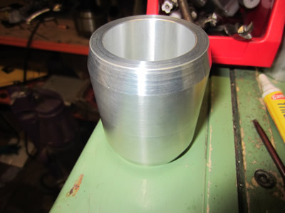
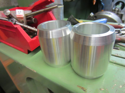
A chamfer was turned at a specific angle using the compound, the part is complete for now, I made another one as there are two fork stanchions. There is a little step where the parts haven't quite aligned due to the inaccuracy of the chuck, I will have to made some kind of a mandrel so that I can hold the tube using the inside, I can then take a final skim in the lathe.
Hello, if you have enjoyed reading this project, have taken an interest in another or want me to progress one further then please consider donating or even sponsoring a small amount every month, for more information on why you may like to help me out then follow the sponsor link to the left. Otherwise you can donate any amount with the link below, thank you!