Honda Hornet Injection Conversion
March 10/03/2015
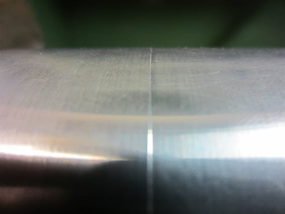
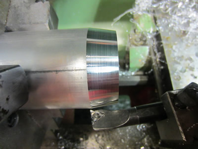
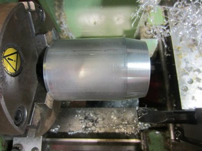
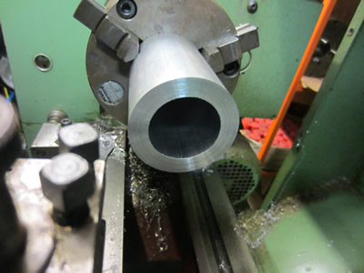
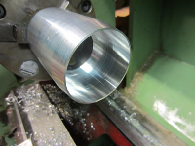
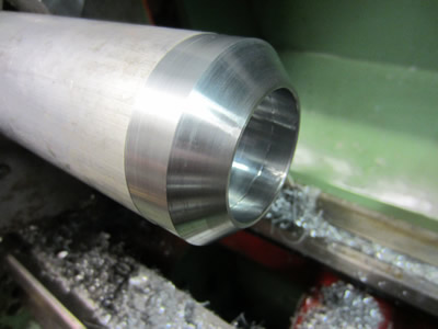
I was not happy with the outside of the parts that I made yesterday, so I fixed this problem. I remembered that I had a small three jaw chuck that I could use to to hold the tubes with their inside diameters. I took a final skim to level the outside.
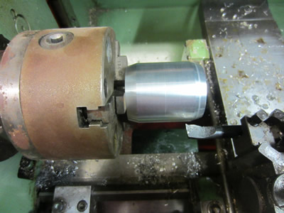
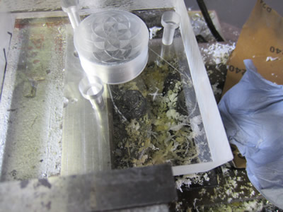
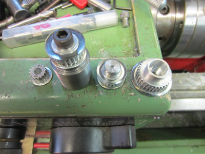
I made a start on one of the gauge housings, faced and bored the inside to suit the diameter of the gauge. The depth of the bore was chosen so that the gauge lense will protrude slightly, it gives a visually better finish around the edges. A chamfer was then turned on the outside, purely for aesthetics.
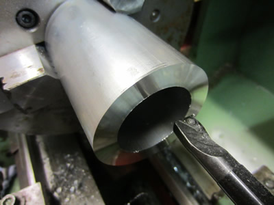
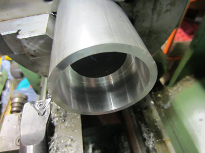
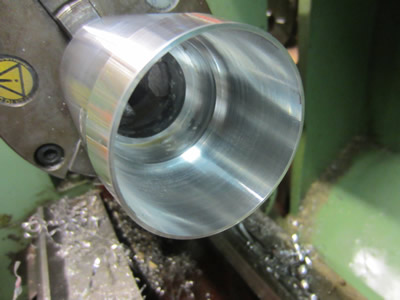
The back of the tube was then faced to give an exact height, a chamfer was turned on the outside. The bore was turned to a round number to allow for a cap, it also gave me something to hold on with the smaller chuck, the outside was then finished.

March 12/03/2015
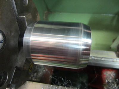
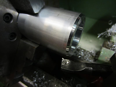
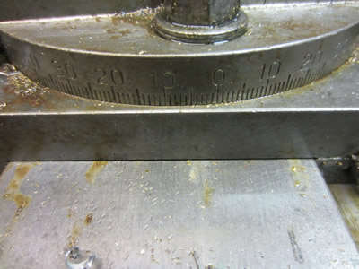
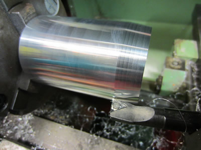
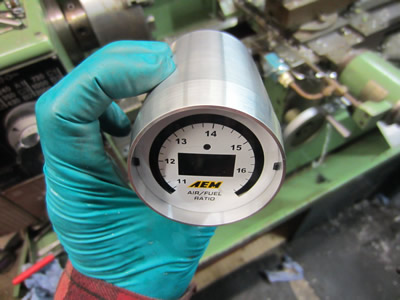
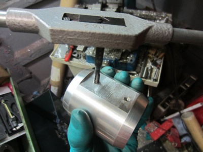
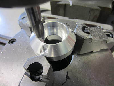
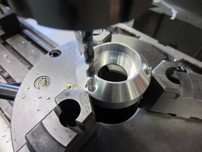
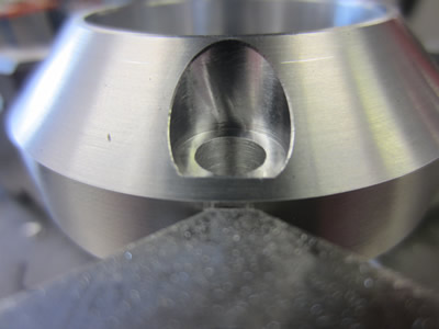
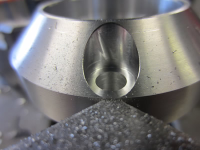
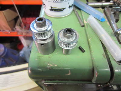
I thought that I would machine things a little differently with the housing for the air/fuel mixture gauge. I started with the back first, faced it and bored out the ID so that I had something to hold onto. The bore that will hold the gauge is 1mm larger than that of what holds the pressure gauge, it meant that I had to turn the OD chamfer at a different angle, 7.2 degrees instead of the original 6 degrees.
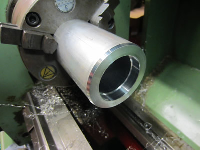
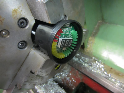
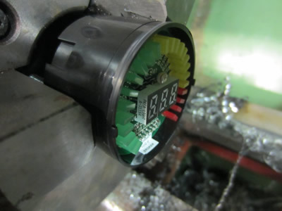
The chamfer and the OD were turned to replicate the look of the other, to say the angle was different, they both look the same. The bore was then turned to suit the diameter of the gauge, slightly smaller for a tight fit.
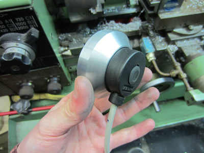
The mixture meter had a bezel on the front that was threaded, it's diameter was too large to fit into the aluminium housing that I had made. I placed it in the lathe lightly, turned a couple of mm off the face and the outside diameter so that it fit snuggly in the housing, all that is now required is the perspex face to protect from water and damage.
March 18/03/2015
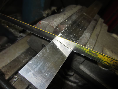
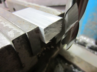
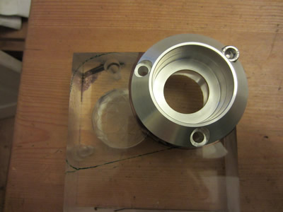
I spent yesterday and today finishing off the mounts for the gauges. I first started off by making two spacers for the mounts, two pieces sawn, milled and drilled from a length of aluminium.
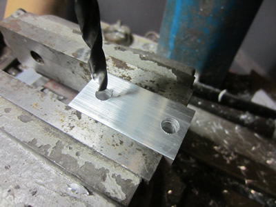
Each one of the gauge holders had a step milled into them to accommodate the spacer, two holes drilled and reamed to suit a bolt.
The same was done to the stanchion sleeves, but instead they were tapped to M6.

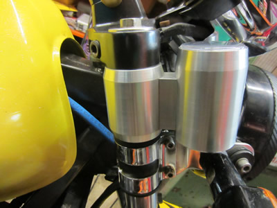
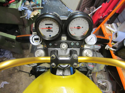
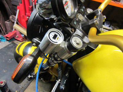
They were bolted together and then placed on the bike, I admit that they're looking pretty good, eventually I will be getting them anodised, probably yellow. I really need some different indicators too, they are huge! Plus I've had some longer brake lines made for the front.
March 22/03/2015
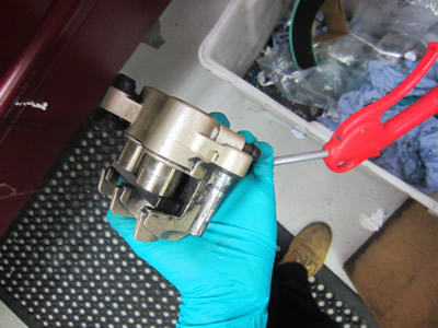
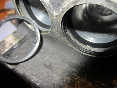
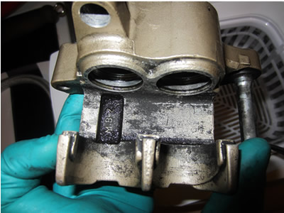
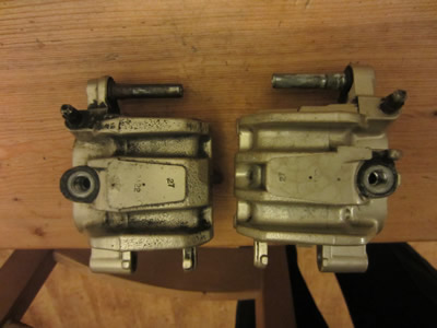
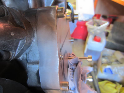
In three weeks there is a biker rally coming up, so I really need to get the bike running, but more vitally, I need some front brakes. Due to me rising the handle bars, the brake lines are now just a little too tight, so I have had some made up a little bit longer. While I'm changing the lines it would also be a good idea to refurbish the calipers. I first started out by removing everything possible, the pistons were rather difficult to remove, requiring an airline.
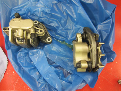
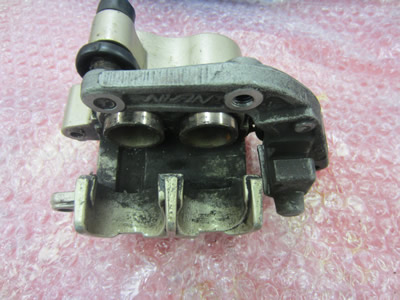
The brakes were starting to bind slightly, which I knew would be caused by the dust seal. Moisture gets behind the dust seal and furs up the aluminium groove, the seal is then pushed out which causes it to get trapped, as you can see in the pictures one seal is torn and the other raised. I had a quick go at cleaning the caliper, but the dirt is really not budging.
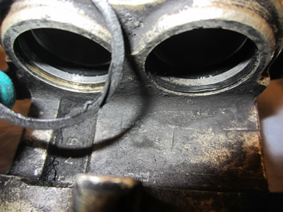
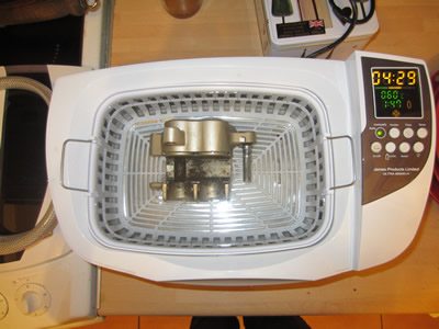
I left a caliper in an ultrasonic cleaner for about 30 minutes, it's removed all of the brake dust, but there is quite a large amount of oxidising. I was hoping that I wouldn't have to paint the calipers, but it looks like I have to.
April 06/04/2015
I've bought myself my dream bike, which means this one doesn't have to ready for the summer. I will finish it of course, but progress may be a little more laid back.
May 04/05/2015
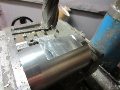
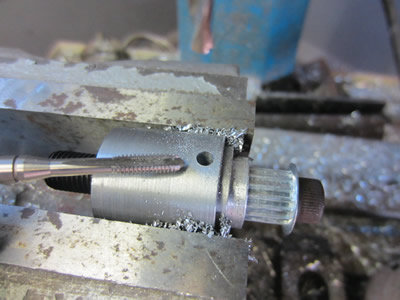
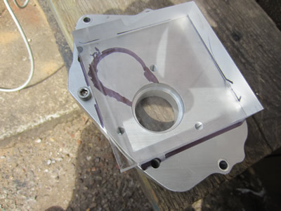
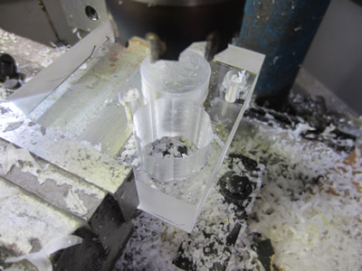
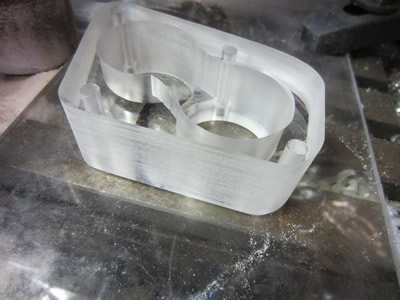
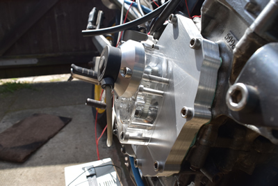
The hornet is now back in my garage, so I can finally get on with it. The first thing on my list was to get the timing sorted out, so I started out by installing a grub screw into the crank timing pulley. I bought myself a 30mm thick piece of acrylic sheet to make the next cover, an outline of the plate itself and the timing belt were drawn on the engine case.
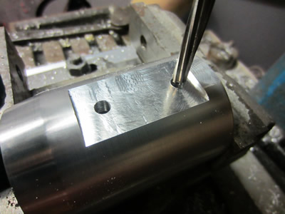
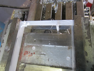
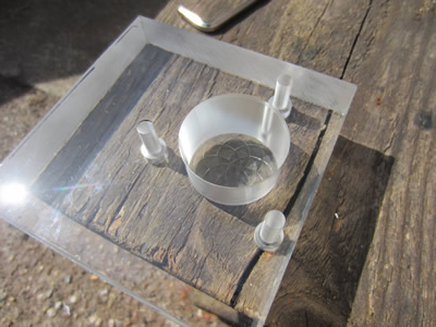
I placed the acrylic over the engine case and clamped it down, it was used as a template to make three holes. The acrylic was then placed into the miller and the holes were traced, drilled and reamed.

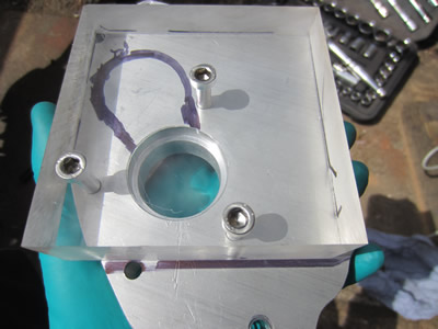
I flipped over the acrylic and recessed the holes to suit an M6 bolt, ensuring that the heads did not protrude. The acrylic was bolted to the engine case, I used it as a template to score a circle for the larger hole. A succession of holes were then made to take out some of the meat to prepare for the next operation.
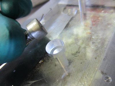
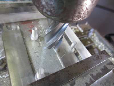
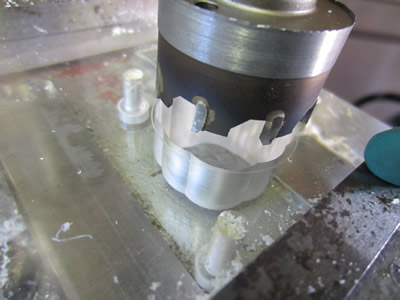
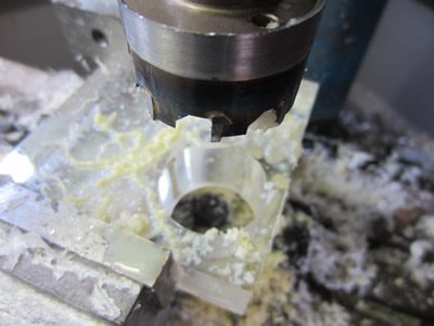
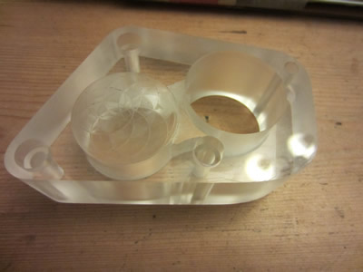
I modified a hole saw in the lathe so that I could use it to finish the bore, I fit the acrylic to the engine case to keep dirt out of the engine. In the mean time I can make a bracket for the encoder.

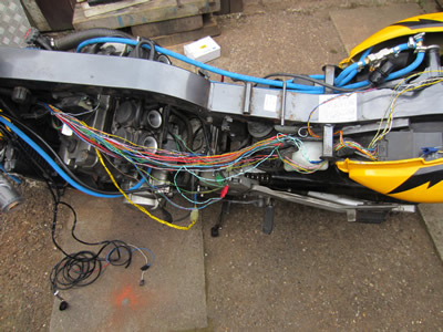
I will design the bracket in my lunch break at work, so I chose to get on with the rest of the bike. I placed on the exhaust pipe and the lambda to go with it, the handle bars, oil and AFR gauges, and a few more bits. I also removed all of the tape and sheathing on the wiring loom, I will be removing the ECU and replacing it with my own version.
May 09/05/2015
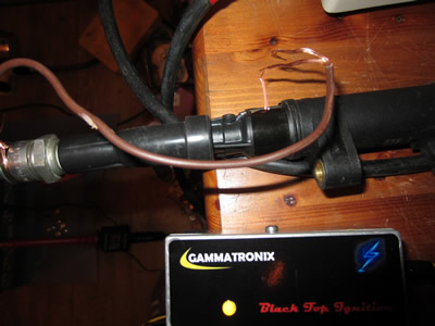
I thought that it may be time to get electrical issues sorted out, so I first stripped the wiring loom and worked out what the wires going to the ecu were for. It turns out that almost all of it can be cut out with very little issue, infact I could just unplug it and splice into a couple of wires. I then had a little play with an ignition module that I bought, it is to replace the points system on an older bike, but it's perfect for what I need.
The module is said to be able to rev to 30,000rpm, I will be running the engine to a maximum of 15000rpm and the system will be working on a "wasted spark" configuration. So the minimum time between fires would be 15000 / 60 = 250 rps. 1 / 250 = 4ms. Due to the module working on points it keeps the coil charged, and I don't want to keep it charged for any more time than I need to, so I will do a couple of "on time" tests ranging from 1 to 3ms, leaving at least 1ms for the off time.
I had a play about with the encoder and wrote a program to read the rpm, calculate the advance and then drive the coils. I spent quite a while making the program as fast as possible, now it did work when I spun the encoder slowly, but any faster and it would not work. It seems that the reference pulse on the encoder is far too fast for the chip to read, I'm not quite sure why though, maybe I should run it at a faster speed and use more chips to do the processes separately. I wrote the simple program below to test the encoder and it would not pick up the reference channel still.
Start: if pinb.1 = 1 then goto label_1
goto Start
label_1: toggle c.5
label_2: if pinb.1 = 0 then goto Start
goto label_2
I inserted the command "setfreq m32" to run the chip at 32MHz instead of 4MHz, as shown below. I thought that it could be due to that the pulse length is too short but even at the elevated clock speed I get the same problem.
Start:
setfreq m32
label_1: if pinb.1 = 1 then goto label_8
goto label_1
label_8: toggle c.5
label_9: if pinb.1 = 0 then goto label_1
goto label_9
It seems like there are two options, start learning assembler language, which I will have to do anyway for the rest of the ecu, or I could use logic chips to do some of the work. I intend on linking all of the processes through parallel, using binary, a lot of the logic chips output binary so this is probably the best choice.
May 11/05/2015
I have done a bit of thinking about the ECU, it seems I will have to start learning assembler again, just simple tasks such as delays, digital inputs and outputs. Everything on the bike that is analogue will be converted to digital via a separate chip, most of the processes are to be dealt with by logic chips, they are far more faster and robust than a microcontroller. The purpose of the ECU is basically a look up table, the ECU will read "if" scenarios such as those from the lambda and output the answer in the form of injector pulse length. I haven't gone any further with fitting the encoder to the engine case, this is just incase I cannot get this particular encoder to work properly. I'm hoping that with a couple of logic chips I can get it working reliably, flips flops and binary counters are what I have chosen.
May 15/05/2015
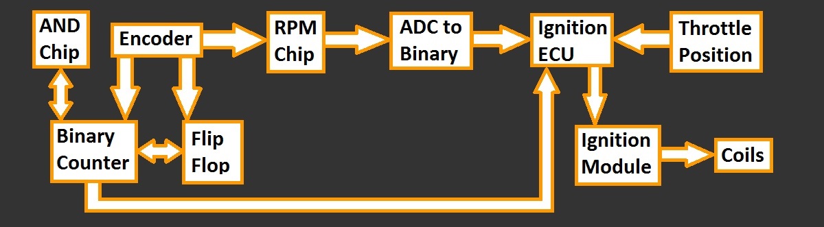
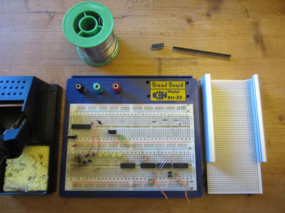
The chips have been received through the post, so now it is time to get things working. I have drawn up a flow diagram to show how each component will be linked in the ECU, each box is a component.
I set to putting the circuit together and then hit another obstacle, I bought a 14-bit binary counter, for some reason there are no outputs for the 2nd, 3rd and fourth bit. It looks like I will have to go and buy another type of chip.
May 25/05/2015
I have revised my idea with the above flow diagram, instead I have removed the idea of a flip-flip, this was to identify the difference between 180 and 360 degrees for the chip to read. I have gone and bought a 12-bit binary counter chip, this time there is an output for every bit. There are a total of 360 increments on the encoder to two revolution of the crank, this means that there will be a spark every 90 degrees. One chip will count to 90 degree, it will then reset and count another chip with the aid of some AND logic chips. The more processing I do using logic chips, the less program I have to write and the faster everything can run.
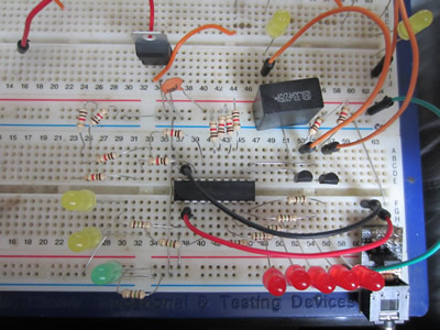
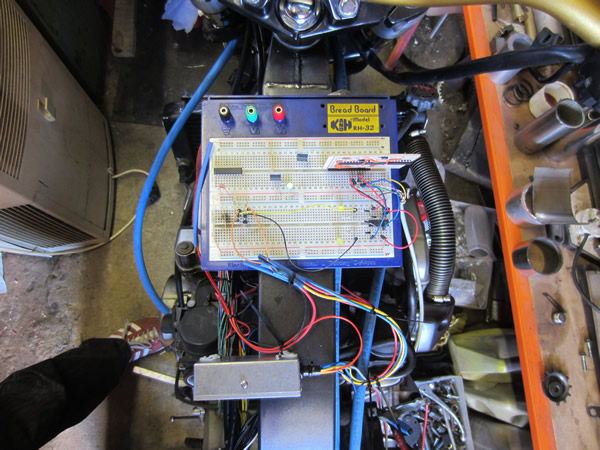
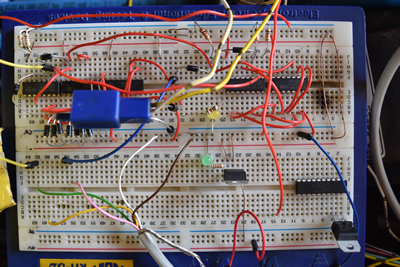
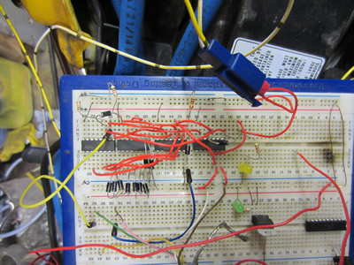
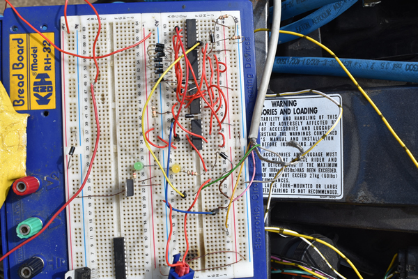
I have put together the circuit onto a breadboard. Each time a total of 90 pulses are read from the encoder it adds one onto a johnson counter, the binary chip is then reset. When the encoder reaches 360 degree (n channel) everything will be reset. I tested the circuit with the encoder, each quarter turn of the encoder caused one of the LED's to shift to the next, after a full revolution the whole thing reset itself. Now that the circuit is working I next worked on the engine case.
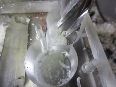
I scored out an approximate hole with a scribe, I then proceeded to drilling it out and then did a final bore with a modified hole cutter. A slot was cut to allow room for a belt to run, I assembled the whole thing onto the bike. It doesn't look that great yet, it's function over form for the time being.
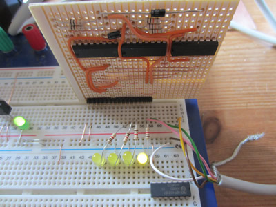
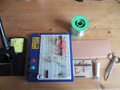
I then assembled what I had on the breadboard onto a piece of strip board, I'm not a fan of flying leads though. I plugged the board back into the breadboard to check it's operation, it worked perfectly. Each of the four outputs were then connect to four separate AND gates, all of the remaining inputs were tied together to be used as an enable pin. The purpose of all this is so that when a microprocessor reads the position (0-90 degrees) and the rpm, it can use only a single pin to control the advance on the AND chip, the johnson counter chip knows which quarter the engine is at, therefore the correct coil is fired.
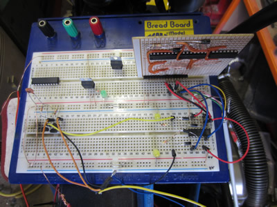
I connected the breadboard up to the ignition, the coils and to the ignition module. The battery was put on the bike and I attempted to start it, it did back fire quite a bit until I found the correct position of the encoder, but after that I actually had the bike running.
The next step is to finish of the engine case and get the advance working on the ignition.
May 27/05/2015
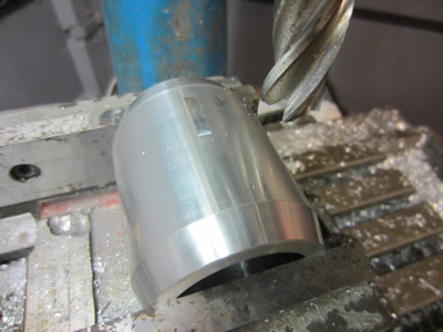
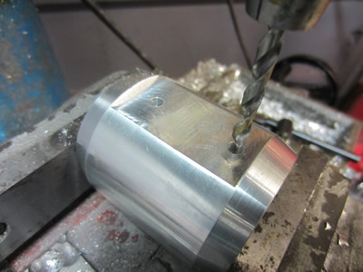
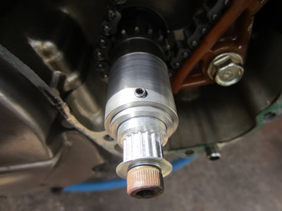
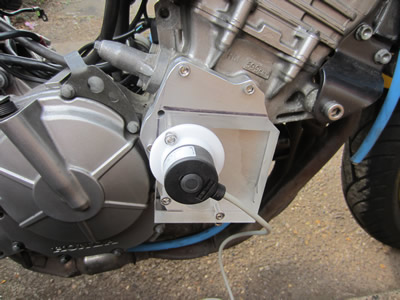
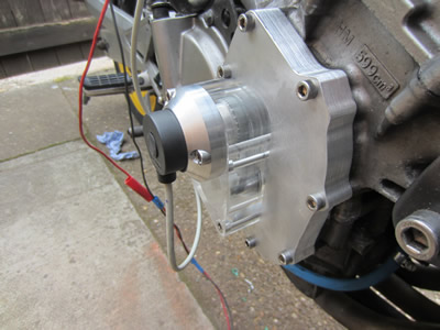
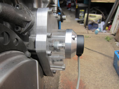
I made a little housing out of polyacetal to test the positioning of the encoder to the engine case. The whole thing worked out ok, so it was time to make everything a little more permanent. I started out with a piece of 64mm aluminium bar, I'm not sure what grade it was but it sure was easy to machine.
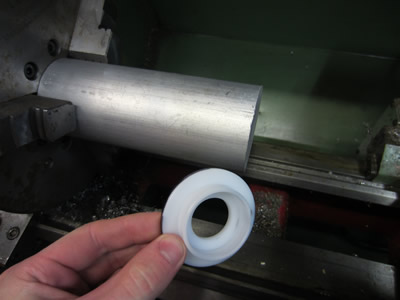
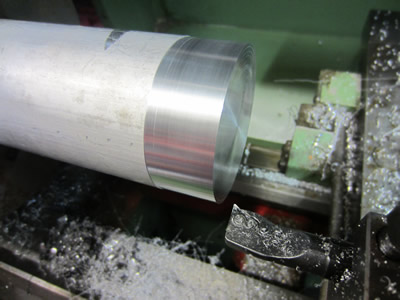
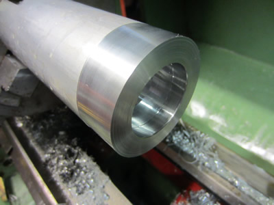
The inside was drilled and bored out to suit the encoder, the aluminium was that good that I could make 5mm roughing cuts. I turned on a chamfer at the front to make it blend a little better with the encoder, the whole thing was then parted off.

May 28/05/2015
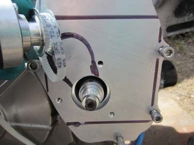
The housing was clocked in a miller, a recess was made which was followed by a hole. A total of three were made, this will allow me to bolt it to the engine cover.

I placed the housing a little too deep in the jaws which meant that I couldn't go deep enough with the recess. I first accepted it, but it played on my mind, so I stuck it back in the miller and made them a little deeper. The perspex was marked up for the band saw, which will be followed by sanding and polishing.
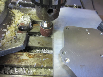
May 29/05/2015
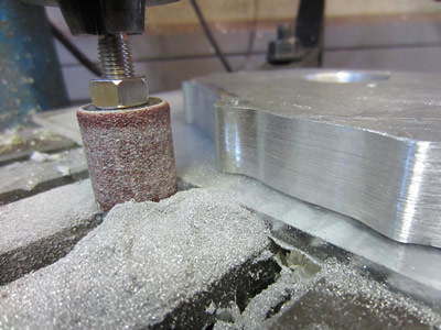
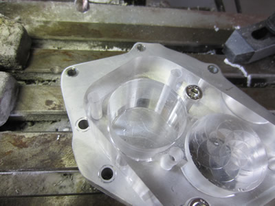
I bought myself a drum sander to profile the edges of the engine cases, as you can see in the first photo the edges are not that great. It took quite a bit of time to get it all square, but I was very happy with the result.
The next part was the clear engine case. It was first cut up with a band saw, then I used a drum sander to profile the edges.
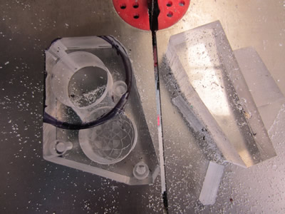
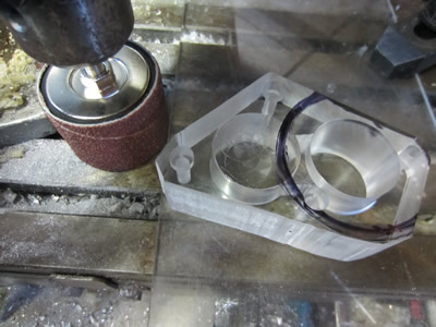
I wanted the edges to be clear so that I could see the timing belt, so using progressively finer grades of sand paper I almost got it clear.

May 30/05/2015
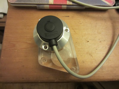
The sensor was placed on the perspex as a template to make some holes, these were drilled and then the aluminium engine cover was tapped. Everything was cleaned up and assembled.
June 07/06/2015
I assembled the timing sensor last week and could not get the bike to run properly, infact I couldn't even get it to fire on all four for more than a few seconds. It turned out to be the timing pulley at the sensor which was loose and therefore it wasn't keeping the timing. I fixed the problem and then set the timing to fire at top dead centre, the bike still would not fire. I got rather frustrated with the whole thing and put the bike back to the standard timing to see if it would run like that, it wouldn't. I came to the conclusion that my ignition module must have killed the coils, I have yet to test the coils.
June 10/06/2015
There is nothing else it could be with the bike, I even replaced the plugs to no avail, so I just bought some more coils instead.
June 20/06/2015
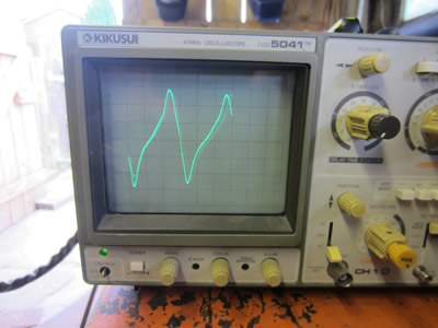
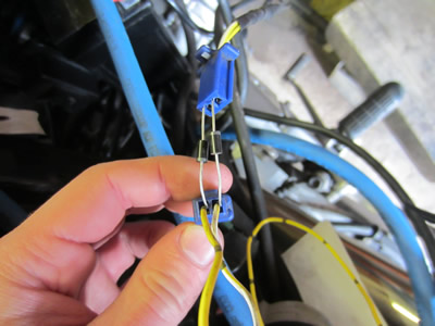
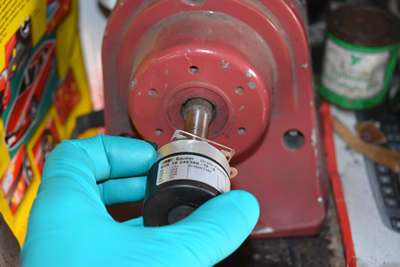
I got the coils through the post, they were from a newer model and the leads were a different length, luckily I could swap them over. The bike took quite a bit of starting, but it did start. I realised that the ignition module I had previously used was out of the question, so instead I'm going to make the encoder communicate with the existing ECU. I first worked out what kind of signal the ECU would need to receive by connecting an oscilloscope to the timing sensor. The sensor is known as an inductive type which when a piece of ferric metal is passed across it produces an AC pulse. I figured that this pulse will be converted to a DC pulse by the ECU and then it will be processed by the computer. I put two diodes in series with the sensor to transform it to a DC pulse, the bike still started as normal. All of this means that a single DC pulse from the encoder will be able to interact with the ECU.
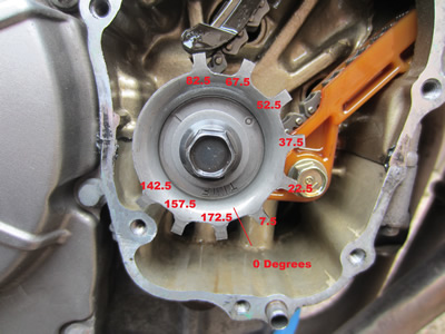
My next task is to make the encoder circuit send a pulse at the correct timing. A complete revolution of the crank equals a total of 180 degrees on the encoder, but the first segment on the timing disc is not top dead centre. I will need the control circuit to send a pulse to the ECU at the increments as shown in the last picture, the TDC will be set by removing a spark plug. The circuit shouldn't be too difficult and will be completed by a couple of logic chips, I want to keep things robust.
June 24/06/2015
The encoders reference point has been set 8 degree's out from top dead centre, this is so that when this pulse is received it will replicate the segmented disc. A chip will then continue to count each pulse from the encoder, when 15 counts have passed it will increment a decade counter, reset itself and start counting the next 15 degrees. The decade counter will count up to a total of twelve, it will then reset. A number of diodes will be place between nine of the counter pins and an AND gate chip, the pulse that increments the counter chips will also pulse the AND chip. All of this will result in a single pulse every 15 degree on the encoder (30 degree on crank) to the ECU, where there are three segments missing on the disc will be unused pins on the decade counter.
July 07/07/2015
I've been away on holiday for a couple of days, so it gave me a little bit of time to think. Before I went away I made the circuit above which consisted of five logic chips, all of this when I could simply do it with three if I just ignore setting the reference point at TDC. The problem is that a decade counter will only do ten, I need a total of two chips to get the twelve outputs that I need. There are only a total of 9 segments on the bike which don't start at TDC, but I can offset the reference point to compensate for this. I didn't want mess around with offsetting the encoder because it means that the injectors will require a lot more effort in mapping their opening times.
July 10/07/2015
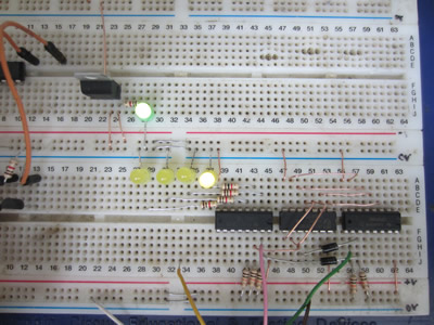
I prototyped a circuit on a breadboard to replicate the segmented disc. A binary counter counts up to 15 where with the aid of an AND gate increments a decade counter, it also sends out a pulse to the ECU, the binary counter resets to count another 15. The decade counter will only count up to nine where it will latch the clock enable stopping it from counting further, the nine segments have now been replicated. Another binary chip counts up to 180 where with the aid of an AND chip resets every chip to start the process again, the reference on the encoder also resets every chip.
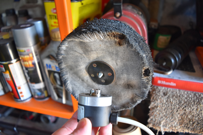
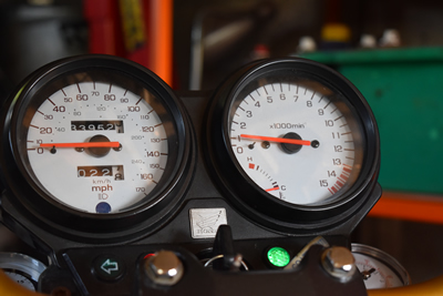
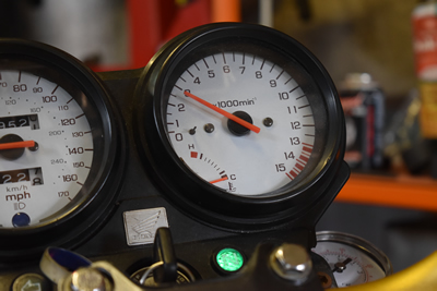
I connected an encoder up to the circuit to test it's operation, for every revolution the circuit outputted two burst of nine flashes to an LED, which will be connected to the ECU. I then connected the circuit to the bikes ECU and then spun the encoder with a polishing wheel, the bikes speedo actually registered an rpm and I could hear the coils clicking.
August 02/08/2015
I spent quite a lot of time trying to get the bike started with the circuit used above, I could only manage to get it running for a couple of seconds. I put the bike back to standard and it still would not run, I feared that I could have somehow damaged the ECU. After removing the sparkplug's and placing them in the oven it allow the bike to start straight away, I must have flooded the engine and petrol fouled the plugs. The bike running rough really did not help with trying to get my own ignition circuit working, but due to the ratio of the pulleys it made getting the timing really difficult. I chose to send for some more pulleys to make the gearing ratio 1:1, it means now that semi-sequential injection will only be possible.
August 06/08/2015
I got my pulleys through the post, I managed to rework the existing metal work to get the new pulleys to fit. I created another circuit to count to 30 instead of 15 and to replicate the nine segments. I connected it up to the bike and turned the sensor with an angle grinder, the tachometer registered a speed and the coils clicked.
August 08/08/2015
I put the new pulleys on the bike and started it, it did run but registered nothing on the tachometer and back fired every ten seconds or so, it was also really difficult to get it started. It's clear that I've got something wrong, so instead I placed the encoder against a bench grinder which spins at just under 3000rpm, nothing registered. I completely reworked the circuit on a breadboard, I seems that I had made an error as the tachometer now registered an rpm, exactly what the grinder is rated at.
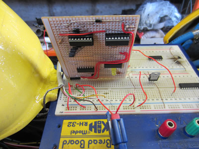
The circuit is really simple as it consists of a binary counter, a decade counter, two AND gates and a dozen diodes. The bike didn't take a lot of starting and the timing was really easy to get right, I will later dyno the bike to get it more exact.
August 09/08/2015
I was really happy with the circuit so I decided to build it onto a circuit board. The board was then coated in a plastic film to stop any water residue disrupting it's function.
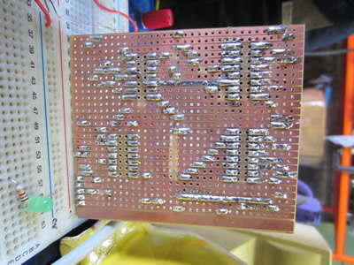
I made another video just to show the board functioning as it should.
Hello, if you have enjoyed reading this project, have taken an interest in another or want me to progress one further then please consider donating or even sponsoring a small amount every month, for more information on why you may like to help me out then follow the sponsor link to the left. Otherwise you can donate any amount with the link below, thank you!