Honda Hornet Injection Conversion
August 11/08/2015
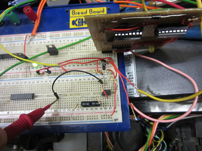
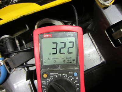
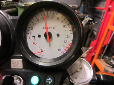
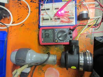
I bought a chip known as an LM2917N which turns an rpm into a analogue voltage source, this source will then be sent to a transistor which actuates a relay and then the injection pump. The purpose of this setup was so the injection pump only runs when the engine is rotating, it must also run the injection pump on the starter motor. I chose some values for components, made some calculations and tested the circuit. I did get pretty much what I calculated, a third of a volt, but when I revved the bike to double the rpm the voltage was not a linear increase like it should have been. I did think that it could have been my signal from the encoder, so I created a circuit that made a perfect square wave signal, it still didn't raise linear, so I put it down to the frequency being too low. The circuit does however operate to an extent enough to register the low rpm's when trying to start the bike.
August 13/08/2015
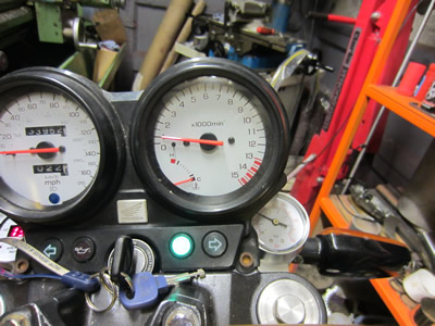
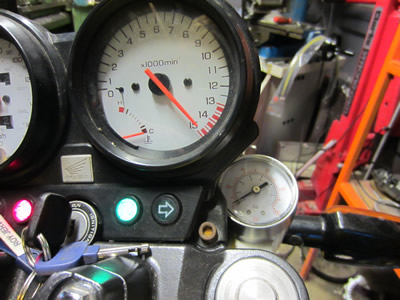
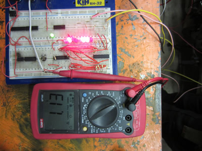
Having played around with an rpm chip I did have some thoughts to whether the encoder and my circuit would be able to operate up to 15000rpm. I checked the datasheet for the encoder to find that the maximum frequency it can switch is 50kHz, the encoder will be giving out 90kHz at this kind of speed. I didn't have much doubt that my circuit would handle these speeds as logic chips can easily operate in the MHz range. I couldn't rev the bike to this as there was no air box on the carbs, plus if I did and the setup didn't function then I could damage the engine. I instead connected a spare encoder up to the circuit and used an engraving tool to spin it. It went up to 15000rpm without any issue, I'm pretty confident in running the engine at these speeds now.
August 16/08/2015
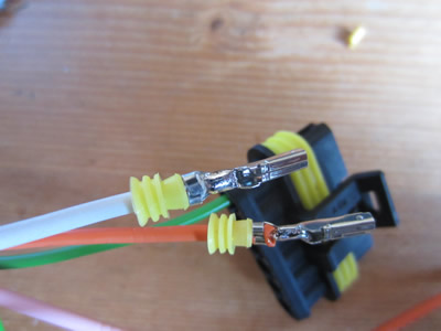
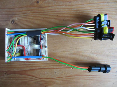
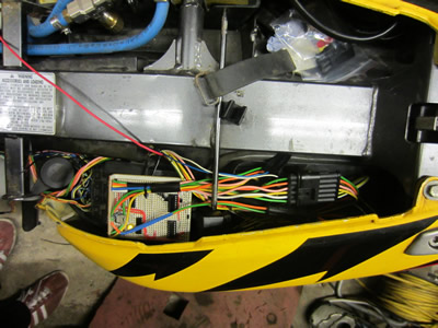
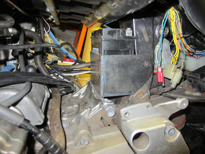
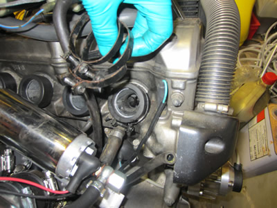
I was happy that the encoder and my circuit board would be able to handle the high rpm's so I decided to get it wired into the bike. I made myself another little board to solder to my existing one, it's basically a breakout board with a voltage regulator for the encoder and logic circuitry. I bought some connectors so that I could remove it all if I wanted to, I soldered all of the crimps for a some added insurance. All of the board has been coated in a plastic insulating film, I do intend on either installing it into a box or encasing it in an epoxy resin.
August 23/08/2015
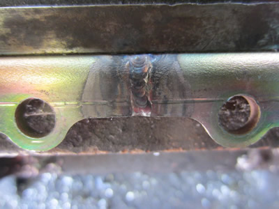
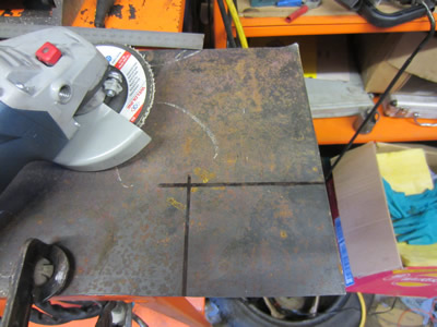
The ignition part of the bike is now running perfectly so I thought it would be time to start with the injection part. The first thing on the list was to sort out the throttle bodies. I had previously used some aluminium angle to make a new bracket for the bodies as I had shortened them by 3mm each. Just one bracket alone wasn't strong enough to stop the bodies from flexing when assembled so I cut down and welded up one of the existing ones.
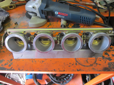
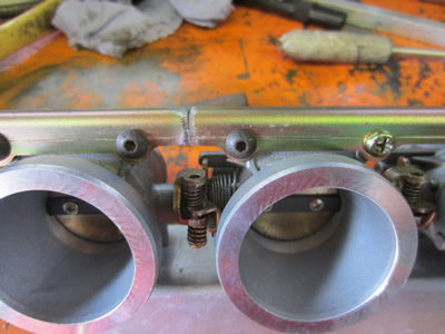
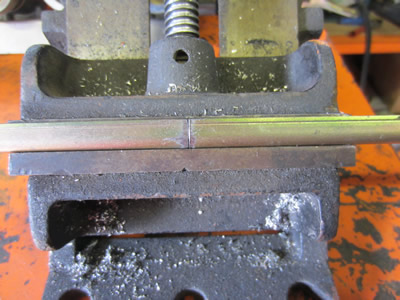
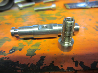
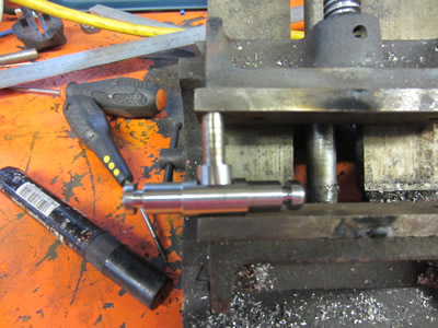
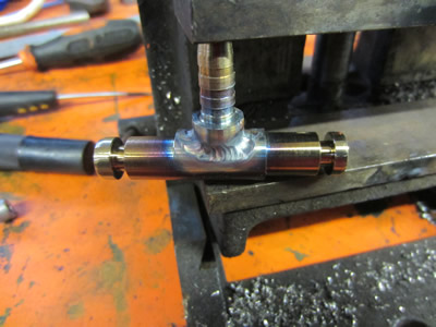
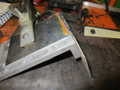
The width of the angle grinder disc was the exact amount that I needed to reduce each section. I used the TIG welder to produce a clean flat weld, having flat welds allowed me to use the vice to hold everything parallel. I next started with the injectors fuel rails, when I welded the injector bodies it caused some parts to warp slightly, it meant that one fuel rail was slightly offset to the other. Instead I machined a piece of stainless with an offset to link them together.
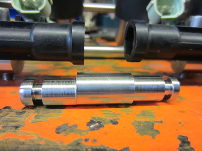
I made it into a tee piece and welded the lot together.
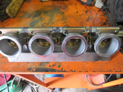
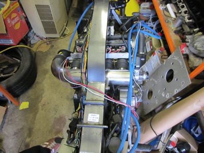
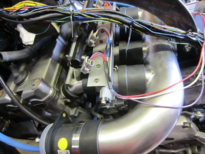
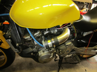
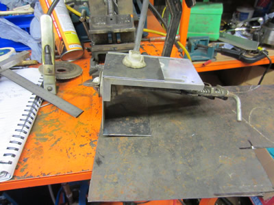
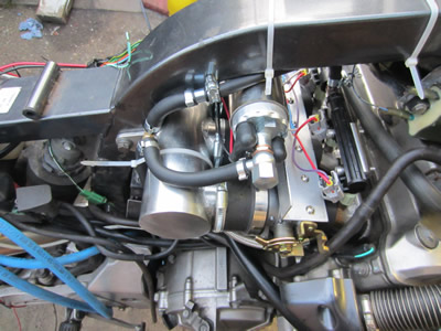
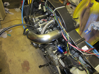
I assembled the injector bodies, the throttle bodies and the air box. I also put the tank and the seat on to get an idea of room and where to put things. There is a huge amount of room beneath the throttle bodies, so I should be able to place a swirl pot, the fuel pump and the fuel pressure regulator there. I'm also thinking about the turbo in the future, there may be the room to put it there, I would probably have to put some kind of shielding there to avoid burning myself.
August 24/08/2015
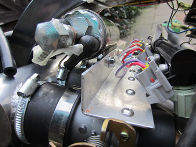
The next part I needed to do was to sort out the fueling system, I first needed to know where to put certain items. The battery was originally integrated into the air box, now that this is gone I needed somewhere else to put the battery. The battery fitted perfectly against the frame and there was also bolt hole from the existing mounting location for the air box. I proceeded with making a box out of some mild steel, I chose to use the TIG instead of the MIG welder as there would be no grinding afterwards, although TIG is less forgiving where there are impurities present.

I welded everything in place using squares to get everything aligned properly, I did however get quite a lot of bubbling in the welds due to me not cleaning the metal prior to welding, I will probably fill in these holes with primer when it comes down to painting the box. To get the hole in the box at the correct position I chose to place a piece of masking tape against the metal, I put the box in place and then hit it with a hammer, the threaded hole in the frame left an imprint in the masking tape allowing me to drill a hole in the correct location.
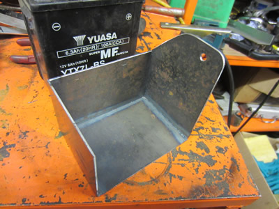
I was really happy with the way that the battery box had turned out. I now need to locate the position of the swirl pot, the injector pump and the fuel pressure regulator. I should have no problem in placing the swirl pot in front of the battery box and the fuel pressure regulator at the side of the battery box. I'm hoping to place the injector pump beneath the petrol tank as it's huge, my only problem is that the pump must draw fuel up from the swirl pot. I can't see any reason why it shouldn't be able to but I will have to test that this is not an issue first. I have ordered some fuel hose and some accessories for the fueling system, so I must now wait.
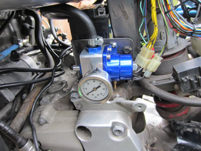
August 26/08/2015
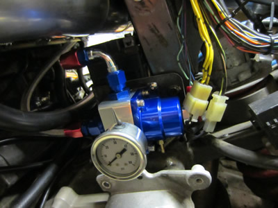
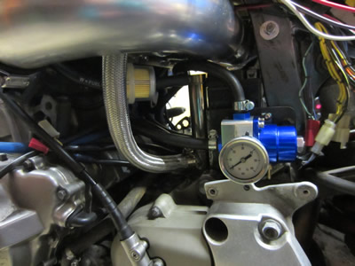
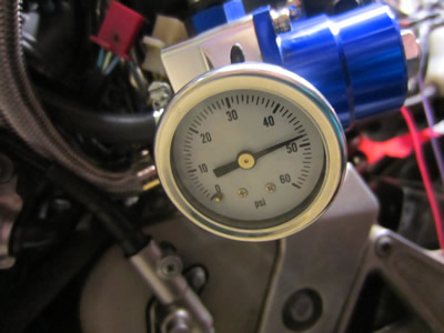
I received all of my bits through the post. The first thing on the list was to make sure that the fuel pump would be able to draw fuel and wouldn't need to be gravity fed. In the process I also connected up the pressure regulator to ensure that nothing would leak, to my surprise I got a leak around the pressure gauge at a very low pressure. I had some thread sealant which worked a treat. I only took the pump up to 45psi which will be it's working pressure. I spent quite a bit of time doing little bits like replacing the screws on the throttles bodies with button allen bolts, placed some hose clips on the rubbers to the air box, placed the O-rings into the injector body assembly and then finally worked out where the injection pump would go. Ultimately I ran out of time in the day otherwise I would have made a mounting bracket for the pump and then proceeded with the fabrication of the swirl pot.
August 29/08/2015
I needed to sort out some kind of a mounting bracket for the fuel pump. I was originally going to use a steel strip and mount it above the throttle bodies but I found some tube that the pump only just slid down. I cut the tube to the correct length and then cut out some strips of steel to allow it to bolt to the throttle bodies. I welded both of the strips to tube but then removed one of them as I had to bend the bracket quite a substantial amount in order for the pump to clear the petrol tank.
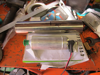
Once I got the bracket in the correct location I then pressed the pump into it, I placed the petrol tank onto the bike to make sure that the pump cleared it underneath, it was only by a few mm's. I had to remove the petrol tap in order for the tank to fit properly, this is due to it fouling on the injector bodies. Instead I will be machining an adapter to screw into the tank and then placing a self-sealing fuel coupler inline with it and the swirl pot. I decided to plumb in the fuel pump to the injectors and left a surplus amount of pipe for the swirl pot. I drilled and tapped some holes in the battery box, the fuel pressure regulator was then bolted to it.
August 30/08/2015
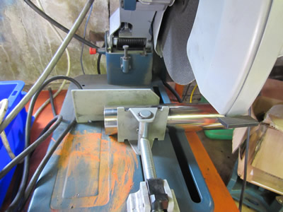
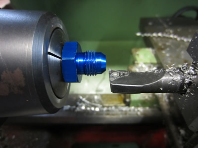
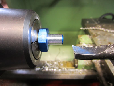
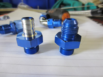
I bought the fuel pressure regulator as part of a kit and it came with quite a lot of hose couplings and adapters. All of the hose couplings were designed to be used with thin wall fuel hose and then to be sheathed in a braid. The sheath is quite difficult to cut and finish, and all of the hose that I have bought is reinforced, apart from the pump inlet hose which I will have to sheath. I placed some of the adapters in the lathe and turned them down to suit a 8mm hose.

I screwed the new adapters into the regulator and placed the output pipe from the pump and injectors onto it. I spent quite a bit of time pondering what size swirl pot, how and where it should be mounted. The purpose of the swirl pot is to provide the injector pump with bubble free fuel, hard acceleration, cornering, low fuel and hard braking may disrupt fuel flow from the tank.
August 31/08/2015
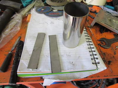
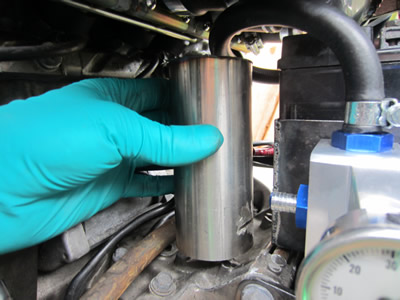
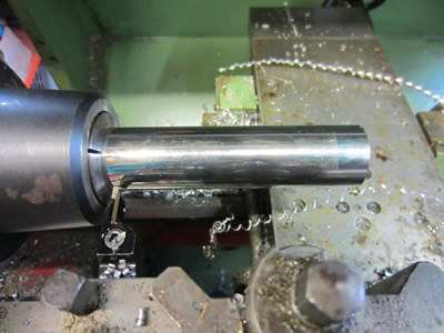
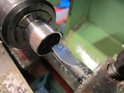
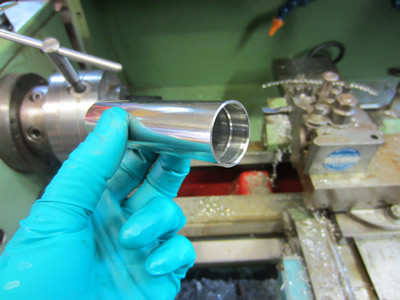
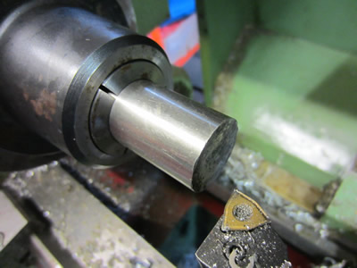
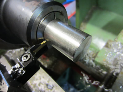
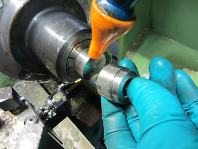
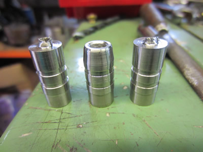
I decided that the size of the swirl pot does not need to be huge, so I opted for some one inch stainless tube. I chose this as the end caps would be easy to make and so would the hose barbs. I first started out by chopping down the tubing in the lathe and then bored out both sides to an exact diameter.
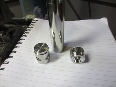
I found out some scrap pieces of stainless and chopped them down to the required length to be used as end caps.
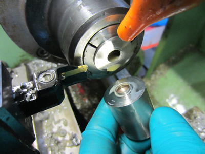
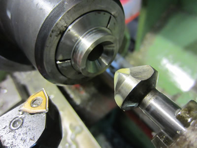
I drilled both of them out to a depth shorter than the overall height of the cap. A step was then turned on the outside so that it would press into the tube I prepared earlier. In the top cap of the swirl pot I turned a large counter sink to help air bubbles rise to the top.
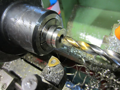
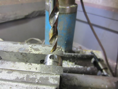
Each of the caps were drilled out to accommodate a hose barb.

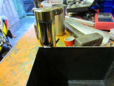
I turned some hose barbs, three to suit a 8mm hose and one to suit a 15mm hose. I welded everything together by using TIG.
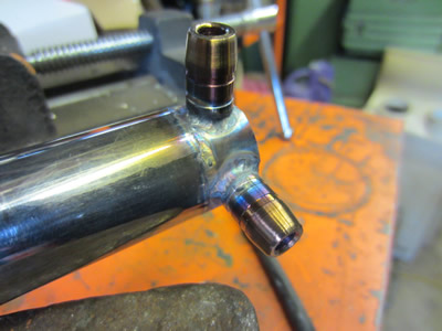
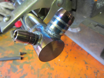
I needed somewhere to place the swirl pot so I welded it to the battery box, mild steel and stainless can be welded together with little issue. All of the pipes were plumbed in, the pump intake pipe is not reinforced so I sheathed it with stainless braid. I fed some fuel into the pipe where the petrol tank would be, connected up the fuel pump to a car battery and set the fuel pressure at 45psi. Just for the sake of it I turned the bike over and quickly struck the injector leads over the car battery, the bike fired up for a second. All I now need to do is to put some hose clips on the injector bodies and get the electronics sorted out.
September 01/09/2015
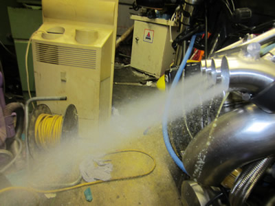
I removed the injector and throttle bodies ready to fix them in place with hose clips. Before I fixed everything back in place I wanted to ensure that all of the injectors were spraying fuel like they should, I did afterall clean everything before fitting so there should have been no doubt. The fuel regulator pressure this time was slightly higher than what I set it at, maybe I need some kind of power regulation to the pump or maybe it's because I had it connected to the fuel tank and there was a slight vacuum caused by the fuel tap valve. I quickly connected up the injectors up to a supply, I was really surprised in how much fuel the injectors really produced, but I was happy that they all looked consistent. I then proceeded with the hose clamps, I used some of them off the existing carbs.
September 02/09/2015
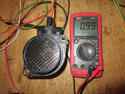
I found a datasheet very similar to the MAF sensor that I bought, from this I deduced what the pins were for and then wired it up to a supply. The voltmeter showed a 1V standard voltage, when I blew through the sensor it showed an increase in voltage. I connected it up to the bike along with an oscilloscope to see what kind of signal I would be dealing with, a pulsed analogue signal as I expected. I will have to make some kind of circuit that averages the voltage and resets every cycle of the engine.


September 03/09/2015
The MAF sensor is only receiving a pulsed supply of air and therefore it's output will be pulsed too. The pulsed output is more similar to a sine wave rather than a square wave and will vary dependant on the engine's rpm and what position the throttle is at. It looks like I will have to make some kind of circuit that takes an average over one engine cycle. I did buy some ADC chips to convert the signal into something a microcontroller can understand, using an ADC pin on a microcontroller will only slow it's function. The ADC chip will be coupled to a microcontroller along with the encoder, every ten pulses the chip will save a reading from the ADC chip, when a full cycle has been completed an average will be calculated and outputted by the microcontroller. After every cycle the microcontroller's output will be updated, it means that each cylinder will get approximately the same amount of fuel based on the amount of air entering the engine.
September 08/09/2015
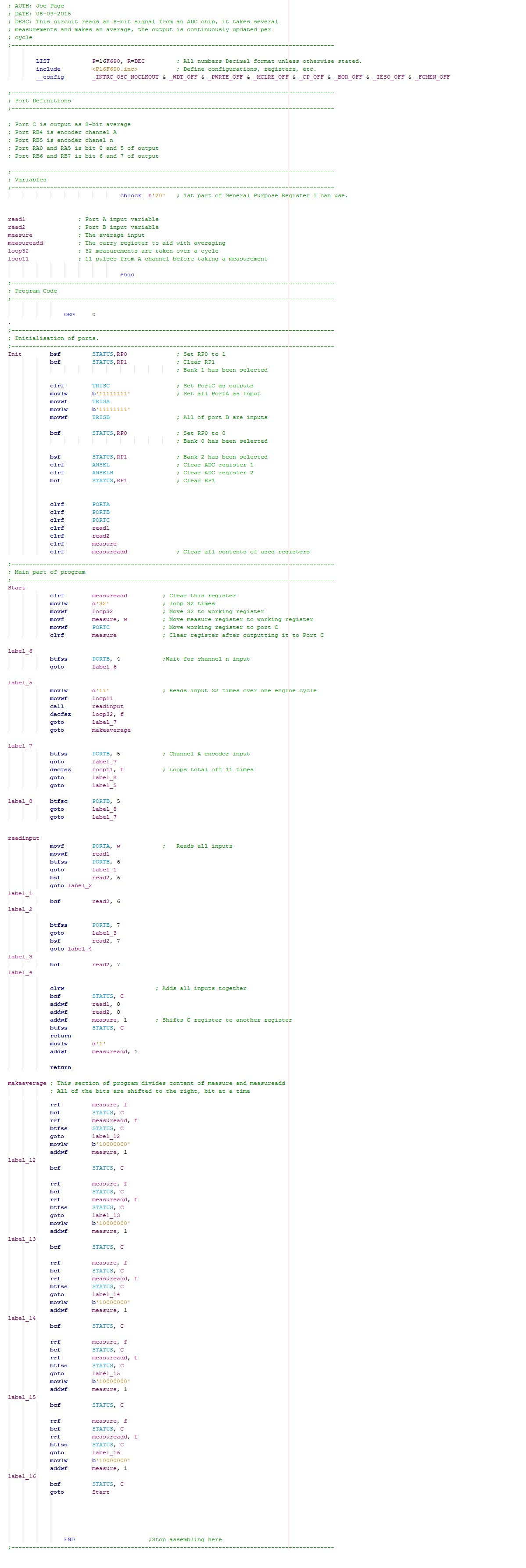
I have spent the last few days learning MPLAB or MPASM, it is an assembly type of language used to program microcontroller's. I'm by no expert but I have managed to get my circuit to function properly, I'm pretty sure it could be cleaned up or shortened in some ways, but I don't yet know how I can improve it. Below is the program;
September 09/09/2015
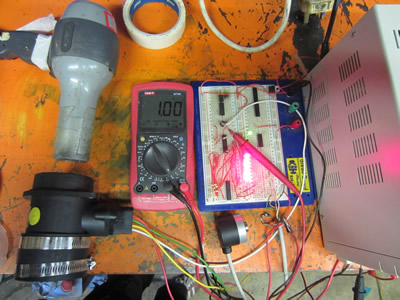
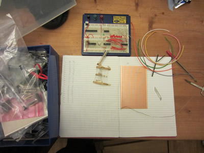
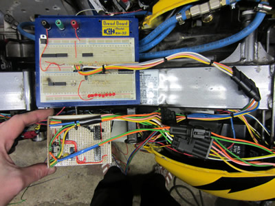
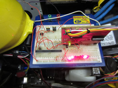
I put the whole circuit onto a breadboard before finalising the circuit on something more permanent. The circuit worked by reading an input from the MAF sensor which is then read by an ADC chip, the microcontroller reads the 8-bit signal along with the signal from the engine encoder, the microcontroller makes some calculations and then outputs it as an 8-bit signal, as shown by the illumination of the LED's. I checked the operation by passing air through the MAF via a hair drier and then by rotating an encoder, the output seemed to stay consistent. I then hooked the MAF sensor to the bike and turned the engine over, the output remained relatively consistent.
I decided to spend the next few hours building all of this onto a circuit board. I again chose to use strip board as making an etched board is far too time consuming and I don't have the setup.
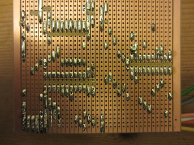
September 10/09/2015
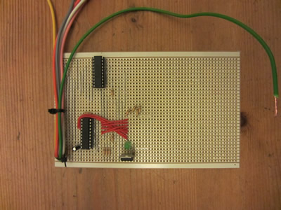
 The circuit board was split in half and then some headers were soldered in so that I could plug it into a breadboard. A loom was then added so that I could plug it into the rest of the bike's harness. I powered it all up and turned the bike over to ensure that it was all still functioning properly, it was.
I thought that it may also be wise to run the microcontroller as fast as possible so that there are no issues when running at the higher rpm's. The following line was added into the initialisation part of the program.
movlw b'01110000'
movwf OSCCON ;Set internal oscillator to 8Mhz
September 11/09/2015
I have a number of spare microcontroller's, PIC16F628A, these will be used for the next process, the engine mapping. I'm not going to go crazy complicated with the injection control system, I will only be using the MAF as an input sensor. The throttle position is not necessary as the volume of air entering the system is known and the lambda will only be used for my tuning purpose, it may become a closed loop system if I have issues maintaining a consistent fuel/air ratio.
There will be a total of three chips, one to determine the firing order and position of the injectors and the other two to map the opening times of the injectors. The first chip will take the channel N output from the encoder to start the process, it will then read an input from a series of dip switches which will determine the firing position, it will then output to the mapping chips of when to fire. I may also include an advance for when the rpm gets faster it fires the injectors earlier, but once the engine gets to a certain speed advancing the injection makes negligible difference. I will instead use the dip switches to get the advance correct on the tick-over, this will then allow the bike to be responsive from a standstill.
September 12/09/2015
About a year ago I did a lot of research into engine calculations such as engine power, injector size, air flow, etc... I learnt that turning the injectors on for longer does not increase engine rpm, it is simply kept the same. There has to be a ratio of air to fuel which means that if the same amount of air is reaching the cylinder then the same amount of fuel needs to be too. The purpose of MAF or MAP sensors is so that the ECU knows what load is on the engine combined with the throttle position, it is the lambda sensor that keeps everything in tune.
I built the circuit that I said I was going to and it worked exactly how I intended it to. I fit the tank to the bike, connected up the injection pump and managed to get it running. I knew that I needed to do some calculations on how long the injectors need to be open for, it was also too late to be running the bike.
Writing this I realised that I had infact programmed all of the chips wrong, I made it so each pair of injectors fired twice per engine rotation when it should have been only once. By doing this it meant that each injector was firing four times per engine cycle, when it should be two, semi-sequential injection.
I had a quick search around on the internet to find what cc my injectors were, they are apparently 270cc. I plugged in some numbers on my calculators page and it worked out to be around 250cc, so the above figure does sound about right. I plugged in some numbers to suit my bike, it says that I need an injector "on" time of 4ms, that would be if injection was sequential, it means that an opening time of 2ms will be chosen. I reprogrammed all three of the chips to suit all of these new parameters.
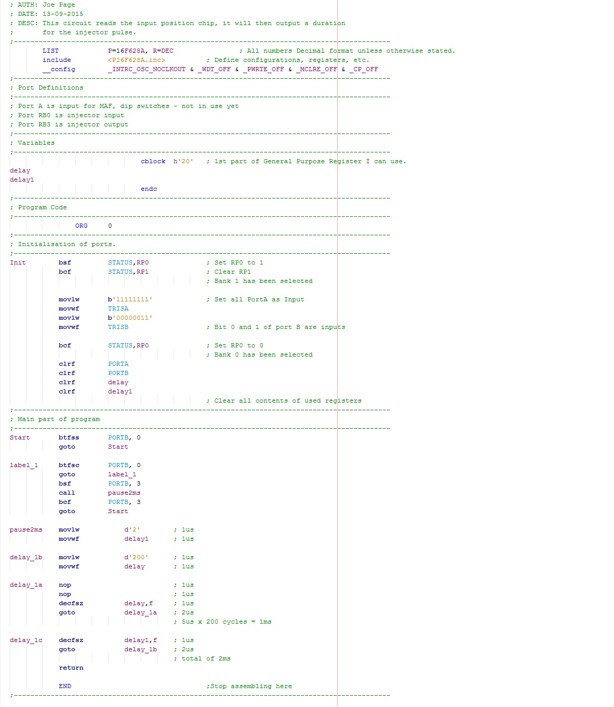
September 13/09/2015
Below is the program for the injector positions, I chose to delete the part of the program that advances the injectors.
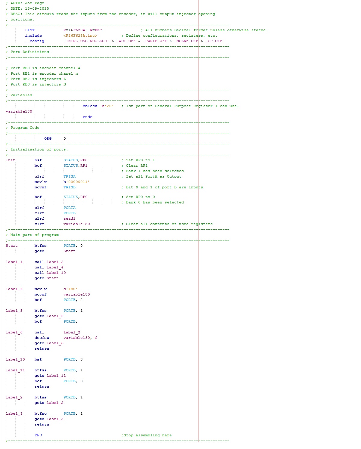
The program below turns the injectors on for a duration of 2ms, a total of 4ms per engine cycle.
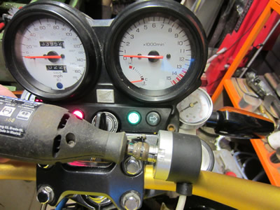
I connected the injection pump up to a car battery, set the fuel pressure at 30psi so that I would be able to increase it if the fuel ratio wasn't right. I managed to start the bike and the AFR stayed around 10:1 revving it from 2 to 11 thousand rpm. I was extremely impressed that I actually got it all working, especially with that the AFR was consistent. I will do some tweaking to get the AFR to 12:1 and get the fuel pressure back up to 45psi. After this I was not able to get the bike started again, so I'm assuming that I fouled the plugs.
Hello, if you have enjoyed reading this project, have taken an interest in another or want me to progress one further then please consider donating or even sponsoring a small amount every month, for more information on why you may like to help me out then follow the sponsor link to the left. Otherwise you can donate any amount with the link below, thank you!