Honda Hornet Injection Conversion
September 14/09/2015
I altered the program so that the injector would turn on for 1.5ms instead of 2ms, I believe that this should be enough compensation with the added fuel pressure. I tried to start the bike to no avail, I think that there could be blocked injectors as I did manage to get some contaminants into the fuel breather pipe.
September 21/09/2015
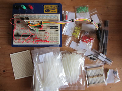
I now have the time to put all my time and effort into the bike. Today I ordered a load electronic components ready for when everything is running right. The programs were changed slightly to suit a better layout on a circuit board. I attempted to start the bike again and for some reason I could only get one cylinder to fire, I ran out of time in the day so I left it. I need to clean the injectors as I think this is the problem, I did manage to contaminate the fuel through the swirl pots breather. I will also install a filter between the fuel pump and the injectors to ensure that no impurities can clog the orifices.
September 22/09/2015
Quite a busy day. I received all of my components through the post, I didn't do anything with them as I wanted to get it all running right first. I also went out to collect a load of bits; carb cleaner, some easy start, hose clips and while I were out I picked up some accessories for another project. I got home and proceeded with installing another fuel filter. I made sure that I gave myself plenty of fuel hose so that the injectors could be removed easily.
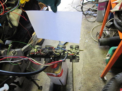
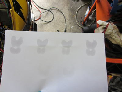
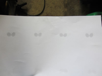
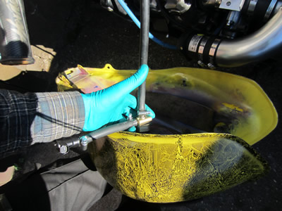
The injectors were then installed on their previous throttle bodies, this was so that they didn't blow apart when I pressurised them. I first pressurised the system and held the injectors open, they seemed to be working absolutely perfect. The second test was to hold a piece of paper about 4 inches from the injectors, then to open them for a short duration by turning over the engine. I was looking for all of the shapes to be the same, they all were (the outside injectors opened a cycle longer than the inside ones, hence the larger shape). The last test was to turn down the injectors opening times until no fuel was injected, then to increase the opening time just enough for a small spray of fuel. I was happy with all of the tests and installed the injectors back on the bike.
I attempted to start the bike to no avail, I must have fouled the plugs with the last starting attempts. I spent about an hour cooking the plugs in the oven, heating them way too hot with a blow torch and they still wouldn't spark. I instead went out and bought some iridium plugs, they were expensive, but the last lot lasted over 18000 miles with a harsh life. The plugs were installed and the bike started, it was running way too rich so I managed to turn down the opening times just enough to get it running around the 11:1 mark, still too rich, but at the limit of the injectors. I made a video, the injector pump is quite noisy due to air in the system, the video does show the bike running at 12.4:1, this is due to the lambda being cold.
Now my big problem is the injectors, they are running at their limits which could cause them to spray inconsistent amounts of fuel. The bike they are from runs a sequential injection setup, therefore each injector only sprays every two engine rotations. With me running the semi-sequential setup it means that each injector sprays fuel every engine rotation meaning that the injectors must open for half the time to meter the same amount of fuel. I have re-written the position chip so that the injectors now only spray once per two revolutions, one pair on the first and the other pair on the second rotation. The program is below;
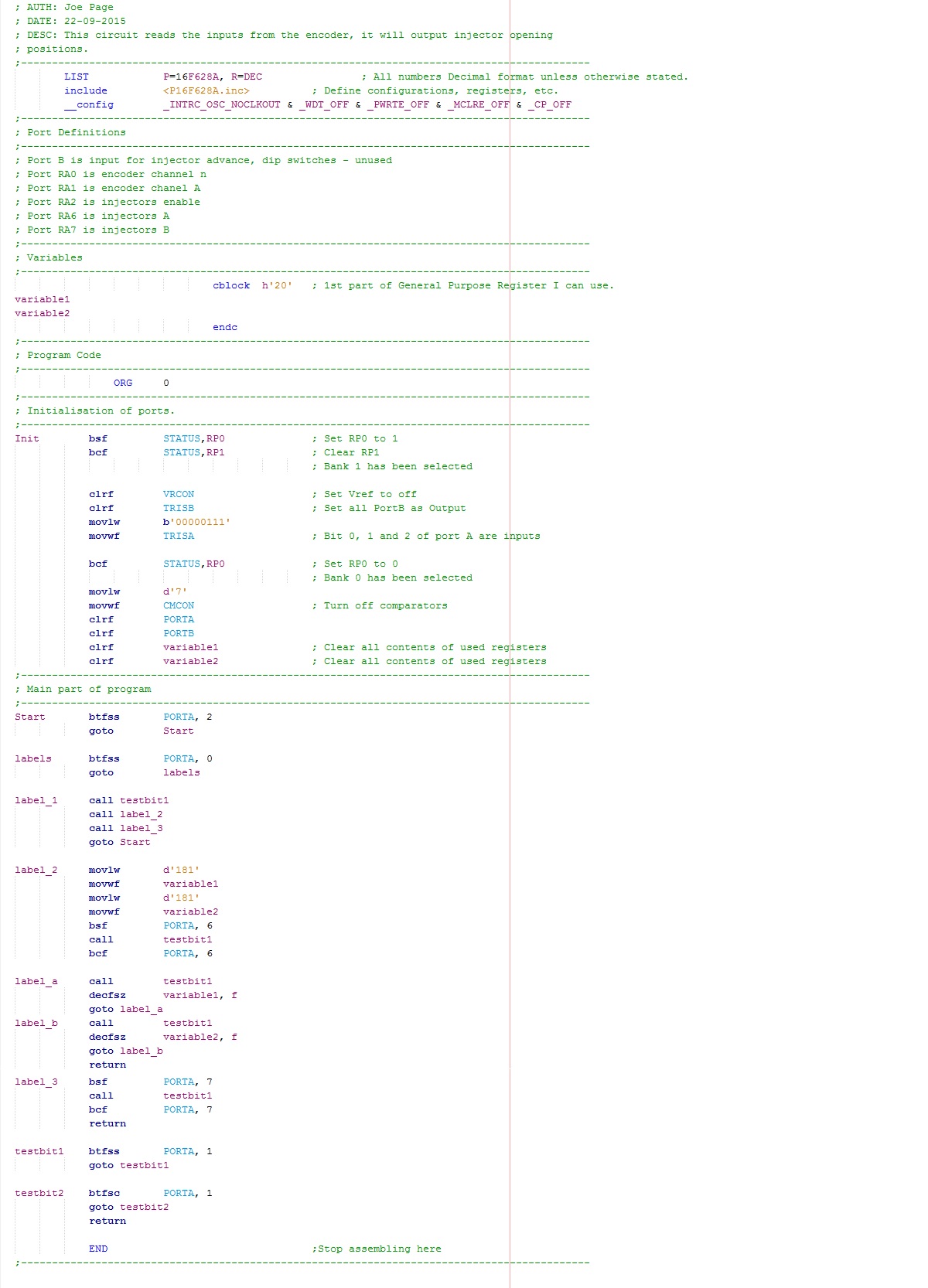
The program will start to cycle when it reads the "n" channel from the encoder, it will output a pulse for injector bank A. After it reads just over 360 pulses from the "a" channel of the encoder it will then output a pulse to injector bank B. Now the encoder has 360 segments, if the program is busy for over this then it will miss the next "n" channel. All of this means that the program will run over two engine revolutions. The only problem is that fuel may not be spraying at the correct time for some of the cylinders, idle may run quite erratic, when the engine picks up rpm then it shouldn't make any difference. I have also written a program for the injector opening times, a logic 0 on RA2 will run the bike at 14.5:1 and a logic 1 will run it at 12:1. I will have to wait until tomorrow before I can test out both programs.
September 23/09/2015
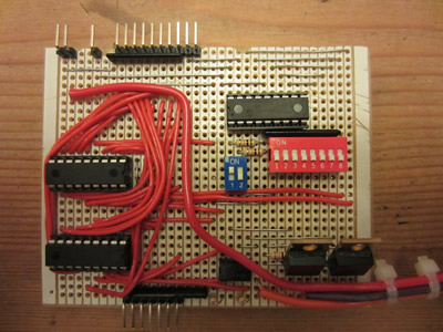
I programmed all of the chips and attempted to start the bike, I could only get it to run on easy start which meant that fueling must have been wrong. I racked my brain for a little bit and realised that I got one of the labels wrong in the mapping program, I fixed the issue and the bike started immediately. The bike is now running at a steady 12:1 and if I turn it to "race" mode it runs at 10:1, still too rich but I'm getting there. My main problem is still the injector pump, I really need to incorporate some kind of bleeding system. For the day I decided to put everything onto a circuit board. I soldered 3/4 of the board and put it onto the bike to see if it still ran, it did. I proceeded to soldering the last few wires in, the ones to the MAF board. When I finished all of the board I tried it on the bike again, something was wrong and it held open a set of injectors without me knowing. Fuel started to pour out of the MAF sensor so I then knew something was wrong. I quickly removed the tank, then the plugs and turned over the engine to remove all of the fuel in the cylinders. I had not fouled the plugs because they still sparked when I turned over then engine, I made sure by putting the plugs back in and running the engine on just easy start, crisis over.
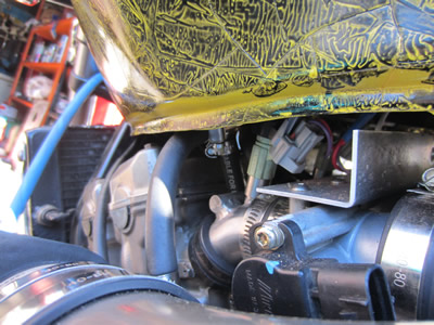
It turned out that due to me setting the MAF sensor input port on the mapping chip as default outputs it caused the MAF board to short against the mapping chips. I spent quite a considerable amount of time checking the board for mistakes and all it needed was for me to assign a port to inputs instead of outputs even if they are not in use. I turned over the engine and all of the injectors clicked like they should, it was too late to try and start the bike so I instead coated both of the boards with a resin spray. There are a total of 6 input pins for the map chips, these will be choke, lambda, race mode, etc... While I'm not using these pins I can use them for mapping, so each pin can be used to select a specific opening time for the injectors. I can use this setup to try and get the AFR down to 14.5:1 and work out properly where the injectors limits are.

September 24/09/2015
I didn't manage to get everything done but did manage to get all of the wiring complete. The two control boards were soldered together via a linking piece of board, a piece of rubber sheet was sandwiched between them to ensure that no shorting would occur. I spent quite a considerable amount of time tidying up the wiring, installing connectors, etc, etc... A relay was added between the battery and everything else that I've installed, it works with the kill switch. The bike still starts as it should, I still need to sort out the fueling problem though as the bike will not rev.
A couple of hours after writing this I had a thought. The bike that these injectors came from has two sets, one for low rpm and the other for high rpm's. I may have to install something like a single point injector that will just focus on the tick-over and low rpm's, when it reaches a certain rpm the second set of injectors will kick in. The MAF sensor will know what amount of air is entering the system and therefore will be able to tell the ecu of which set of injectors to use. I do have a set of injectors from a bike that only uses one set, it's also only 80bhp which means the injectors will be pretty small.
September 25/09/2015
I held off with the idea of an injector to idle, I instead tried to start the bike to no avail, the injector's weren't even clicking. I removed a wire from the MAF as a voltage source to test an LED between that and the injector connector, the LED flashed. I tried to start the bike with this wire removed from the MAF, it started straight away but would cut out if I inserted the wire back to it's location, I have no idea why. I chopped the fuel line to the injectors and inserted a valve so that I could bleed the system. For some reason I was unable to bleed the system completely of air, it seemed to just draw it in, It could be because the fuel pump is placed higher than the swirl pot.
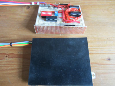
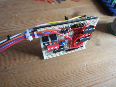
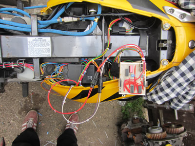
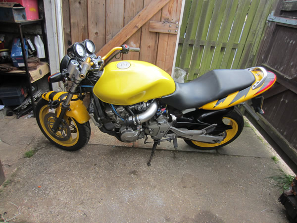
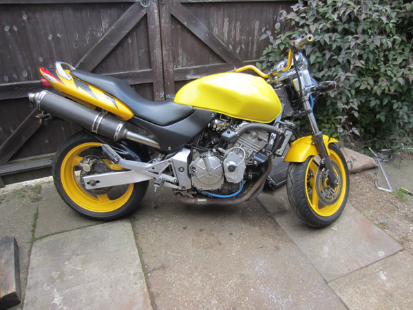
Just a couple of pictures of the bike with the modifications, most people probably wouldn't even notice the difference.
Do I continue with the project? or have I achieved what I set out to do?
September 26/09/2015
I gave myself a deadline to get the EFI system complete by the end of the week, it gave me today and tomorrow. I decided to give the bike a start and reminded myself of all the work that had gone into it, it would be a shame to accept just this.
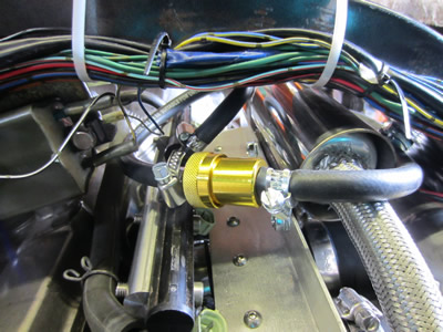
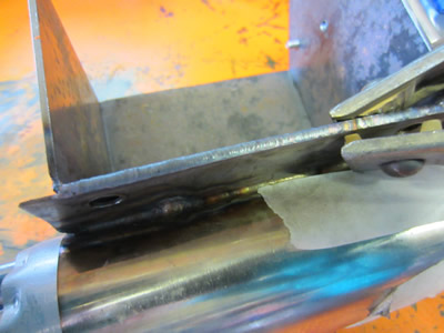
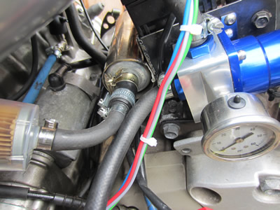
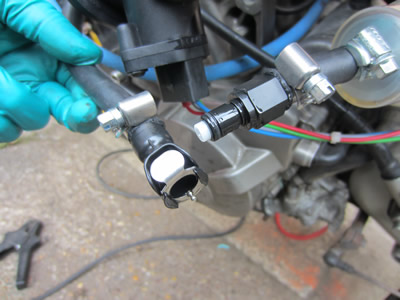
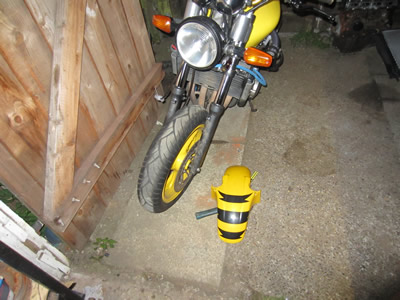
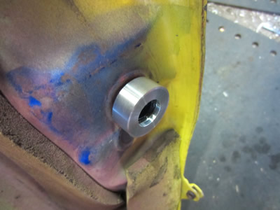
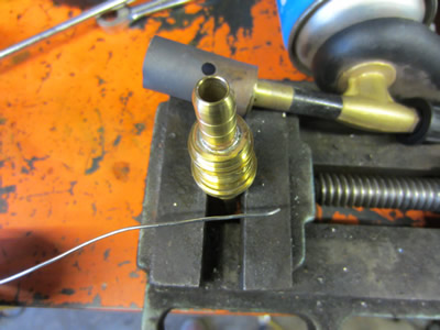
I instead chose to remove the swirl pot and relocate the injector pump from just underneath the tank to where the swirl pot used to be, welded to the battery box.

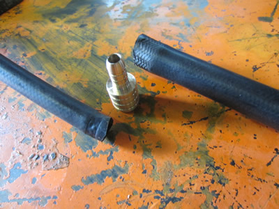
An adapter was made from brass to convert 8mm hose to the 16mm that the fuel pump needs.
I was ready to go but soon as I turned the fuel on this quick release fuel connector started to leak, the O-ring measured 1.4mm thick so luckily a british standard O-ring measures 1.78mm, this solved the leak. The fuel cap was removed so the return could feed back into the tank. I switched the pump on and the pressure was consistent with no "air" noises coming from the pump, unfortunately there was a fuel leak. The fuel was leaking from around the pump where it's crimped together, I guess me pushing it into a housing may have caused a little distortion and therefore causing it to leak. I chose to fill it in with some epoxy resin, the same stuff I used for the injector bodies, the steel reinforced kind.
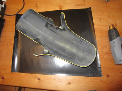
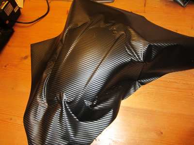
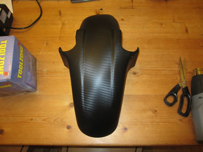
It would take around 8 hours for the epoxy to cure so I instead did some work on the bike. Holes were drilled into the handle bars so that I could install the controls. The clutch lever added and connected up to the engine. I also used the existing throttle cable and connected it up to the bodies, the cable was a little too long but I managed to make do. The front brake lever and hoses were installed ready for the calipers, I need to paint them first though. A set of racing levers were also installed, just because they were sitting in a box doing nothing. I removed the front mud guard so that I could vinyl wrap it.
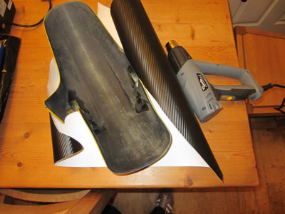
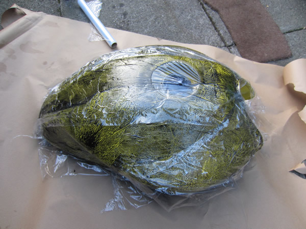
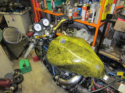
Anything three dimensional is very difficult to wrap, this mud guard took me about 90 minutes. The petrol tank came out perfect when I painted it but the lacquer never set properly due to the glitter spray, it eventually started to crack. I'm thinking of wrapping the tank too, but I imagine it to be rather difficult.
September 27/09/2015
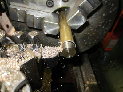
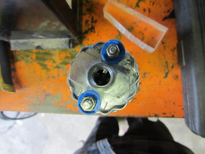
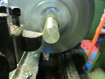
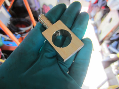
I installed the mud guard and the injector pump. I switched on the ignition and straight away the pump started to leak again. I went on the internet and sent for another one, it was only about £25. In the mean time I thought it may be best to make some kind of feed and return on the tank, I could not use the existing fuel tap. Firstly I cut down some aluminium bar, turned the outside and then bored out to centre. I did not have the correct threading insert, so turned the bore to the correct size and then threaded it the old fashioned way. The cap screwed perfectly onto the tank, so my calculations worked out ok.
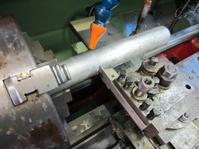
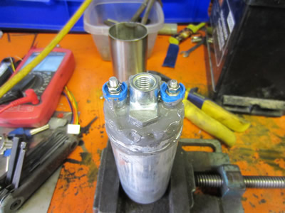
I proceeded to making the next part of of brass.
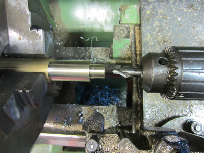
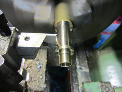
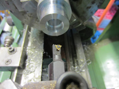
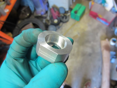
Some grooves were cut to allow for O-rings, a banjo will be placed over them, two holes were drilled to allow fluid to pass through. I also cut a groove for a retaining clip so that the banjo could be removed. I then turned a long straw out of brass, 8mm outside and 6mm inside.
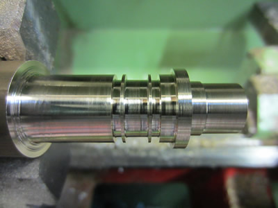
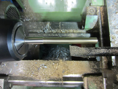
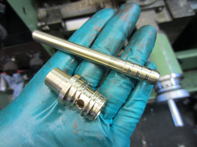
The straw pushed into the first part I made from brass, they were then soldered together. The last picture shows all of the parts fitting together, they will screw to the underneath of the tank. This part allows fuel to drain from the bottom of the tank down through it out of a banjo to the fuel pump, the return from the fuel regulator is then fed up through the straw running up the middle of the assembly, this is so that it does not disrupt the flow of fuel re-entering the system.

September 28/09/2015
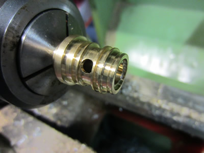
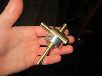
I machined a banjo out of brass to supply fuel to the injector pump. The nut that screws to the bottom of the tank had two flats milled onto it so that I have the ability to tighten it properly. The whole thing was assembled along with O-rings, a circlip to hold it all together.
The battery box was painted to stop it from rusting. I had a crazy idea with the petrol tank, it was sprayed in gloss black and then wrapped in cling film. The cling film was peeled off after a few minutes to leave a funky pattern, I didn't lacquer the tank as the lacquer beneath it was still cracking. In time I will strip the tank of paint and do it from scratch.
October 01/10/2015
I finally got my injection pump through the post today so I installed it along with the new part to screw onto the tank. I filled the tank with fuel and started the bike, the whole system worked flawlessly. I put the brake calipers back on the bike and gave it a run up and down the road. The bike would not run properly on a single map, so I needed to sort out the MAF sensor. The bike would run perfectly when I disconnected the MAF sensor, but would not run at all with it plugged in. I racked my brain for a while and realised that it was the configuration of the chip, one of the data inputs was conflicting with the MAF sensor average chip. I changed this config bit and everything worked perfect again.
I will now create a map that reads the air input and then determines the amount of time that the injector will open for, I'm guessing it's going to be a little trial and error.
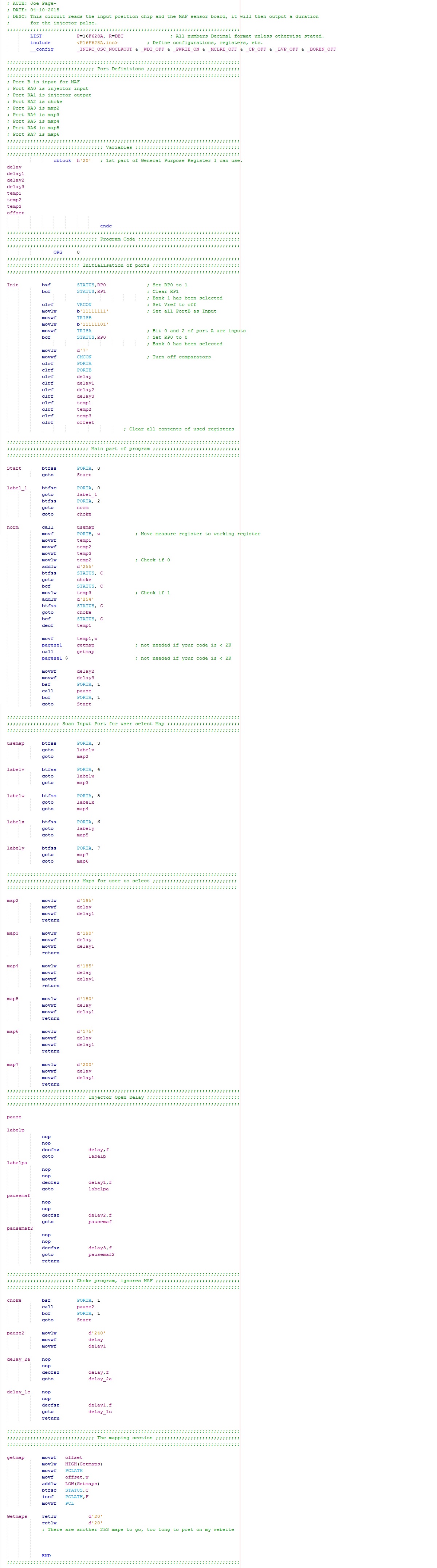
I spent most of my night writing a new program, in basic's it has a total of 7 maps, each one to tune the AFR slightly through the rev band. The rest of the program reads the MAF sensor and adds this to the delay cycle, the more airflow the longer the delay and the injector stays open for longer. All of this is just a bit of trial and error but hopefully I should get better results. My aim is to actually have a map that determines injector opening time through a value that I've set, this would make my program very long so I'm seeking help on a forum on how to decrease it's length.
October 02/10/2015
I got my program sorted out my using a look up table, however the bike is still not rideable. I think that I may have to include the lambda sensor and have a closed loop system.
Late night programming again, I have reworked my program with the MAF sensor, I will have to wait until tomorrow before I can try it out.
On another note, I need to know what the 8-bit number is in decimal coming from the MAF board. This is so that I can see what it's running at a particular air flow, I can then increase or decrease the injector opening time in the map..
October 03/10/2015
It turned out that my bike was not reading the input from the MAF sensor and that it could do nothing with the look up table. I have spent the whole day trying to get my chip to do something with the MAF, no luck as of yet, but I did spend many hours writing a new program that should have fixed the problem.
October 04/10/2015
I finally got the bike running on the MAF sensor using the program below, it did however take a hell of a lot of mapping to get it running properly through the revs.
I have managed to achieve what I set out to do, but, there is a but. I want to ride this bike on the road and simply it's too risky, not that I don't trust my work, it's if I fall off. The bike won't run properly without any of the sensors, especially the timing sensor on the side of the bike which I imagine would smash off quite easily. I'm putting a kit inside of the bike that If I do break it, it will contain the engine cover and the original sensor, it would take about half an hour to get it back to standard. All of the injector setup wouldn't be able to run without this, so I made the decision to put it back to carburettor, at least if I drop the bike I can have it running again within half an hour. First a video with the completed setup;
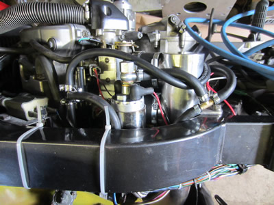
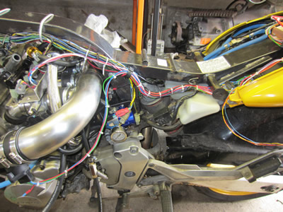
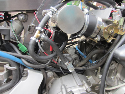
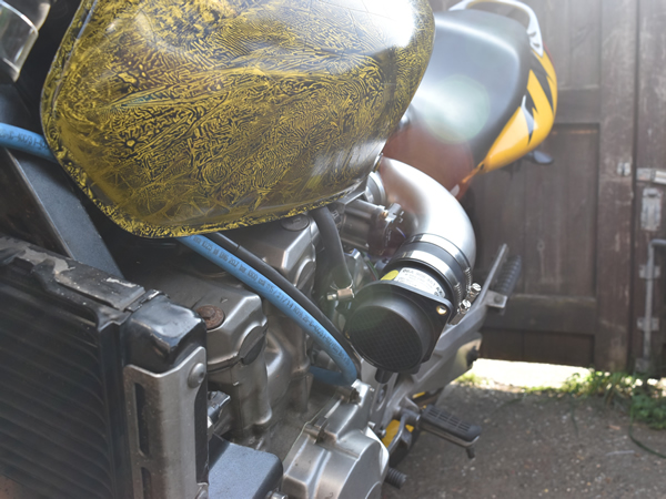
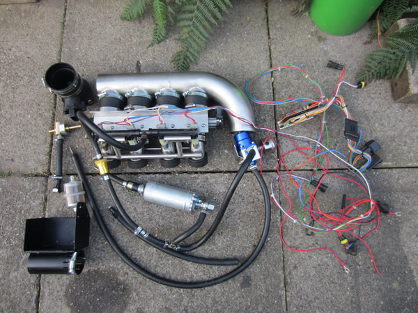
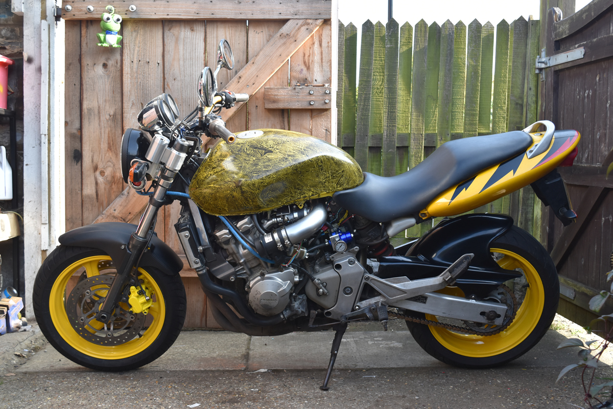
The picture to the left just gives another angle of the air intake, the bike is surprisingly very rideable. The right picture is everything just for the injection system, quite a chunk.
I think I better sort out the cosmetics now.
Hello, if you have enjoyed reading this project, have taken an interest in another or want me to progress one further then please consider donating or even sponsoring a small amount every month, for more information on why you may like to help me out then follow the sponsor link to the left. Otherwise you can donate any amount with the link below, thank you!