Microcontrollers 17 - Dot Matrix Display
If you think back to the LCD in the very early chapters each of the segments are made up of 5x7 matrix dots. The LCD controller, that black chip on the back of the display multiplexes all of these dots. So how is it done, well firstly you could use a microcontroller with a huge number of outputs, this is however not the case. The multiplexing is done using shift registers, each one of these is used to control a matrix. So basically the control chip shifts through each row and column in the first matrix, the shift register then moves on to the next matrix, it moves through each row and column again, the chip shifts through all 40 of the registers and then starts again. It does all of this at such a fast rate that the human eye cannot see it switching between each matrix.
So how is this done with a microcontroller, the 5x7 matrix will use a total of 12 pins. Depending on how many pins the chips needs one can use a pin for every connection on each matrix, or the standard way is to use a shift register / decade counter. Using a shift register means that only two more pins are needed, one to shift to the next matrix and one to reset the registers back to the first matrix. This method is great for ASCII characters to be displayed, this is however for character displays and differs from the way graphic displays work. Another way of doing this is to use microcontroller output pins for the rows and a set of shift registers for the columns. So for example like in a graphic display the microcontroller could for example control 14 rows and a shift register controls 15 columns, the shift register is ideal for reducing the pins required.
I have lots of LED matrices but I'm not going to spend a whole lot of money on circuit board so I will just stick with one of them to show a working display. This program will display a smiling face, I will however integrate this project into another one for a game. Below is the basic circuit diagram required to work a LED matrix.
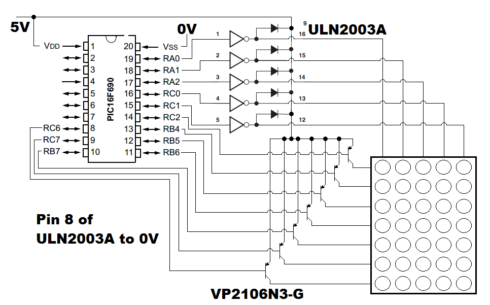
If you remember back to the segmented LED project you have to increase the current when increasing the number of displays, this is due to the fact that each column will turn on and off in sequence, the more sequences, the lower the duty cycle on the LED and therefore a greater current is required to make them brighter. An LED is generally run at 10 to 20mA whereas you may see peak currents up to 500mA for multiplexing. It is the heating in LED's that leads them to destruction, increasing current with a lower duty cycle will use equal power to if the LED was on constant at it's rated current. I have read reports of LED's pulsed at currents of 10A with no deterioration, I really do not recommend this, it would be really bad design. Another thing to notice in my circuit diagram is that there are no current limiting resistors, the more current through an LED yields a larger voltage drop across it, this combined with the voltage drop in the transistors limits the current within reasonable levels.
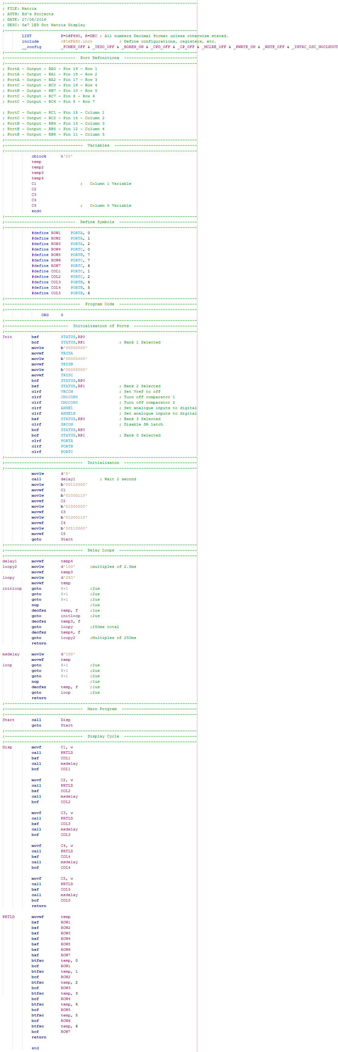
Below is my program, it is very simple and comparable with that of the segmented LED program. The five variables located in the initialisation stage are the pattern to be displayed on the matrix. Since there are no straight ports on the 16F690 I chose to define the ports as symbols, the difference in the program is that I have to convert the variables to individual bits to be sent to the ports instead of sending a whole variable to a port. The great thing with the little section of program is that it inverts the value in the variable, the rows on the matrix are driven by pnp mosfet's which are turned on by pulling the gate to zero volts.
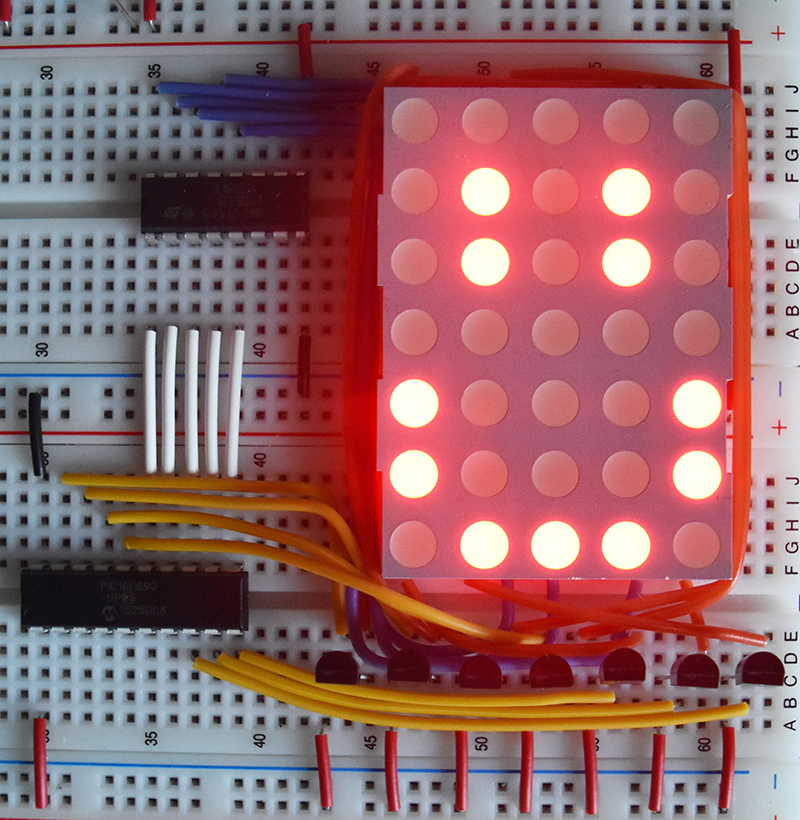
Below is the finished article on breadboard. Due to the size of the matrices I chose to use just one display.
Here is a link to the - Program
I hope this short chapter was useful, I tend not to use these LED matrices as characters displays or graphic displays do a much better job, and are cheaper. These LED matrices are still quite common for sign / message boards as LCD's would generally be overkill. The next chapter will demonstrate the use of a graphic display, the ability to display images.
Hello, if you have enjoyed reading this project, have taken an interest in another or want me to progress one further then please consider donating or even sponsoring a small amount every month, for more information on why you may like to help me out then follow the sponsor link to the left. Otherwise you can donate any amount with the link below, thank you!