Microcontrollers 18 - Graphic LCD
Now we are getting nearer to the modern era, the graphic display, well even this is not so modern, the major difference is things have got faster and smaller. This chapter shows the great amount of information needed to display even the most basic information on a graphic display.
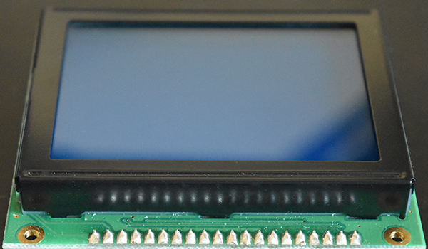
Below is the graphic display I will be choosing to use, it has 128 x 64 pixels.
Like with the character LCD there is a maximum number of characters that can be displayed, so for example with the HD44780 controller there was a maximum of 80 characters. One of my other projects contains a 4x40 display, 160 characters total, to achieve this it simply uses two controllers tied together, the only pins not tied are the enable pins. So one display is really split into two separate displays, this is the same with a graphic LCD.
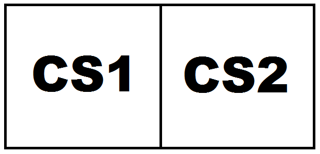
The graphic LCD uses either the KS0108 or the NT7108 controller, they do the same thing so it doesn't really matter which one you get. The NT7108 is limited to a maximum of 4096 pixels or 64 x 64 (of course it could be 128 x 32, etc...). Since we need double this amount of pixels it is natural that we will need two controllers tied together, one controls the left side of the display and the other controls the right. These are normally known as "chip select 1" and "chip select 2", there will be two separate pins on the display that enable each of the chips additional to the enable pin which accepts the input data.
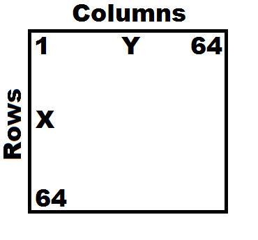
Since I'm dealing with two separate displays I will discuss how to control just one for now as they are both equal. The display is split up into columns and rows, or Y and X which is referred to in some datasheets. I honestly do not know who came up with this arrangement as "X" should be horizontal and "Y" should be vertical.
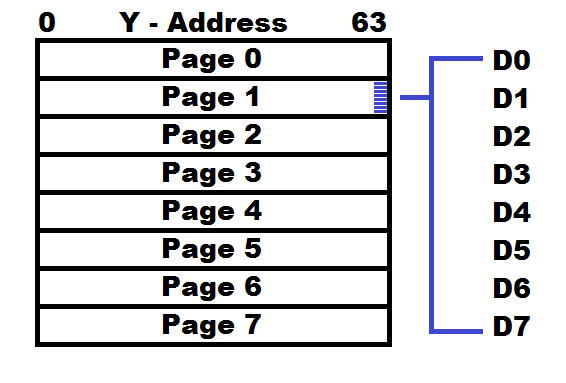
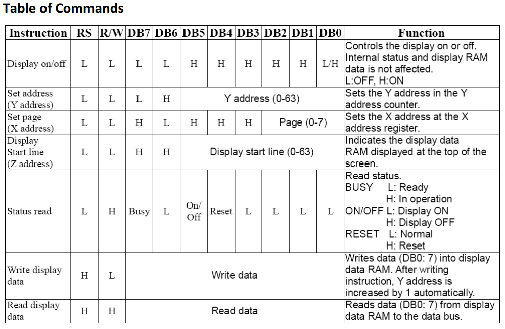
In most datasheets it is stated as "X - Pages" and "Y - Address" which is the columns. Since the 64 bits have been divided up into eight pages it means that each one is 8-bits high. There are eight data lines going into the LCD, DB0 - DB7, each one of these corresponds to a pixel. When starting at the beginning of the display each 8-bit piece of data will increment the "Y" address, when 64 pieces of data have been sent it will begin at "Y0" again, you have to instruct the display to jump to the next line / page.
The commands are pretty straight forward but you will notice that it does differ greatly from a character display. The most simple command is to turn the display on or off, the purpose of this is to save power, it should be noted however that the backlight draws the most current and this is not controlled by the LCD. The X and Y addresses are pretty easy to understand, note that the display will not shift characters and will only overwrite them. The display start line will offset the pages, it is best to leave as zero however it is an easy way to scroll the display. The Ram read is rarely implemented however the status read is used to check when more data can be received, this can also be done on the character LCD, I chose delays instead in that instance.
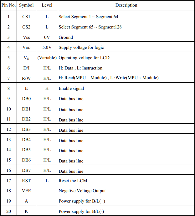
The pinout for my LCD is as follows, there are a few differences compared to the character LCD though. Firstly the contrast requires a negative voltage however the LCD itself on pin 18 will provide a negative 5V, quite simply a potentiometer is placed between +V and pin 18, the center tap goes to contrast. CS1 and CS2 will enable the left or right side of the display, enabling is active low. The reset is not a command and has it's own dedicated pin, this is pulled high for normal operation and low to reset the display, resetting the display will turn it off and reset the page address, it does not clear RAM. R/W this time is used mainly to read the status of whether the display is ready to receive more data or not. RS, E and DB0-7 have the same functions as the character LCD. One final note is the backlight LED, since the display is smaller it only requires about 50mA of current, a resistor of around 30 ohm needs to be chosen.
I have found that dealing with a graphic display is a lot easier to get right the first time as there's no special initialisation procedures like that for the character LCD, like getting it into 4-bit mode (graphic displays do not have 4-bit mode).
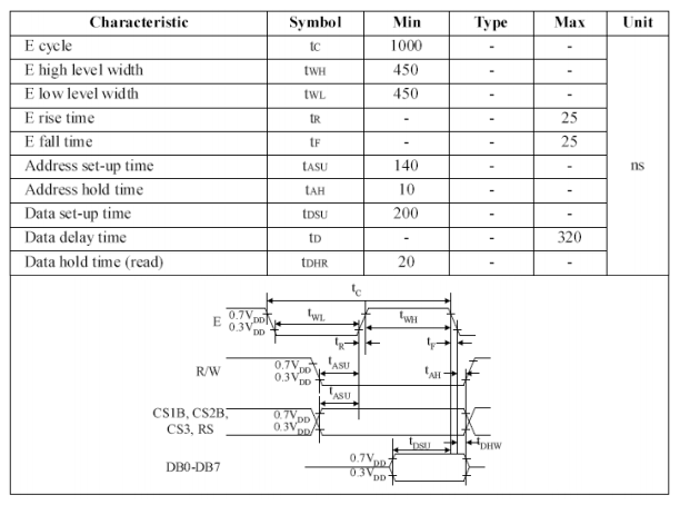
Since the enable is required to be on / off for a minimum time of 450ns it would probably be best to round this up to between 600ns to 1us.
The clock frequency of the display itself is around 250kHz which means that data cannot be sent to the display any faster, around half of this.
One thing you have to remember with these graphic LCD's is that they have to write 8-bits at a time, since we are talking 128 x 64 pixels that would take 1024 bytes of data or just 10ms for the LCD to be written. If however you need less time to write just a single fraction of the LCD then simply an address can be chosen and the RAM over-written at that location, this can save huge amounts of time.
One more thing to note is the maximum refresh rate is only around 5Hz due to the response time of the crystals.
The chip I'm choosing to use for this chapter is the 16F887 as the LCD will use all the pins on the 16F628A, I'm not going to go crazy tying it in with the previous projects either, this chapter is solely to print some information on a graphic display. Before I do we need to come up with some kind of a design to display on the screen, now there are two options when doing this, one is to do it manually by creating a table and the other is to use a software known as a bitmap generator. I have chosen to use the manual method, I don't have the time to create a software so I chose to use excel instead. The process is to find a picture of 128 x 64 pixels, convert it to a monochrome bitmap, paste the image into excel, divide the spread sheet into 128 x 64 pixels, place ones and zeros for black and white, the spread sheet converts the image to a series of bytes, a total of 1024. Below is a section of the spreadsheet, 8200 ones and zeros for a full image can be quite time consuming.
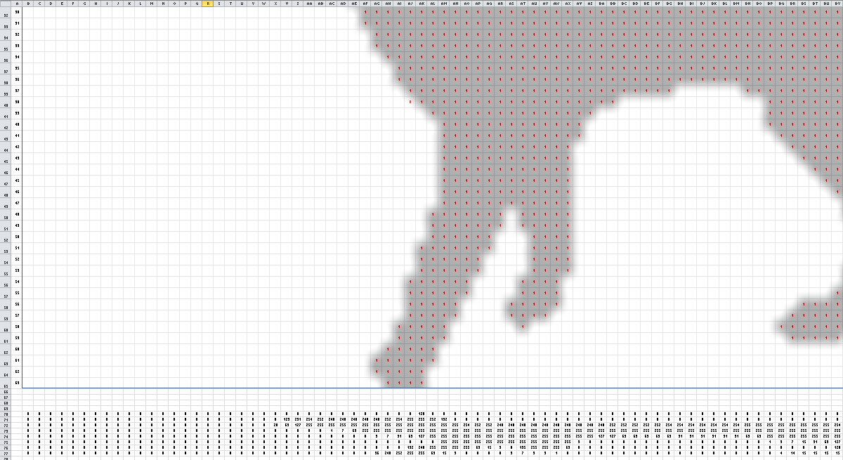
Here is a copy of the spreadsheet - Bitmap Convert
All of this data needs to be placed into some kind of a table, below is an example of how I fit all of the characters into a lookup table which can deal with anything up to the size of the program counter, since the 16F887 can count up to 8192 which is also the size of the program memory the lookup table can be this size minus the rest of the program memory.
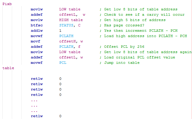
The PCL is only 256 bits which can be written directly, the PCH cannot be written however the register PCLATH will write to the PCH. The data written to PCLATH will only go to the PCH when the PCL is modified.
The program will first read the address where the lookup is located, it will then check to see if the PCL offset will overflow into PCH, so imagine the address is 254, we offset by 2 and add this to the PCL, this will jump forward two places in the lookup table. Now say we offset this by 3, this overflows to zero, the PCL offset will move backwards in the program, to avoid this the PCH has to be incremented by incrementing PCLATH.
"OffsetL" will offset the PCL by multiples of 1, whereas "OffsetH" will offset by multiples of 256, one increments the PCL and the other the PCH. All of this means that the two offsets can offset the lookup tables address anywhere up to the program counters maximum of 8192.
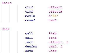
At the start of the program it will clear both of the low and high offsets, a third offset is loaded with the value of 64. The program will then call / fetch a character from the lookup table and then print it to the display. The low offset is incremented and the offset with the value of 64 is decremented. A total of 64 characters are fetched from the lookup table before the third offset reaches zero and causes a branch. The next section after this program will reload the offset three to 64, it will instruct the LCD to move to the next line and then continue to write another 64 bytes to the LCD. After this process has happened four times the low offset has rolled over back to zero, the high offset is then increment in order for the next 256 bytes to be taken from the lookup table.
The LCD does not require an initialisation as such because resetting the display will only turn it off, infact the only initialising that has to been done is to select the appropriate side of the LCD and instruct it to be switched on, the same is done to the other side. Then simply the program will instruct the LCD where it wants to start writing and that is essentially it.
The most important part of the program is writing the instructions to the LCD, this is a little different to that of the character LCD. Before the send program is called the data sent needs to be loaded to the working register, RS also needs to be set whether an instruction or character data is being sent.
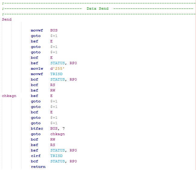
The program is called and the data directly placed into the data line output, I set the symbol to "BUS".
A pause of 400ns is allowed for the data to stabilise, remember a "goto" command will take two instructions whereas a "nop" will only take one, using the "goto $+1" command is a great way to implement a longer delay with only one instruction.
The enable pin is set high then low which tells the LCD to process the data.
Afterwards the data bus is turned from outputs to inputs, the RS line must be set low and read line enabled, this sets the LCD to a status read.
The program will pulse the enable pin to tell the LCD to output it's current status data to the chip. Bit 7 is the busy / ready bit to tell us whether the LCD is ready to receive more data. If not it will loop back to pulse the enable pin and check again.
When it is ready the read is cleared and the LCD sent back to data mode, the data bus is sent back to outputs and the program is returned from where it was called.
The RS line has to be set low every time an instruction needs to be sent due to the program setting it back to data mode after a send.
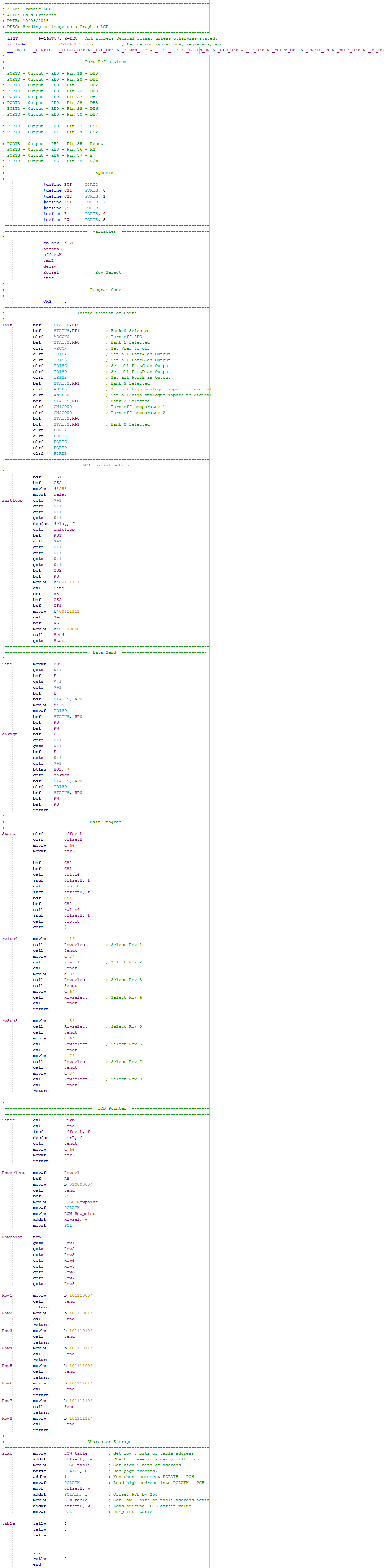
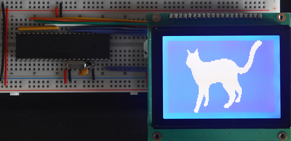
Below is a picture of the full program or the text version is here - Program Text.
And the end result.
I hope that all of these tutorials have been an interesting read, hopefully it has given you some ideas of how to implement external peripherals into your project. All of these projects were intended to show the theory and the processes in how to control the microchip and how to drive external sources, please take time to view my other embedded projects. My other projects are used in the real world either for entertainment, domestic, automotive or industry.
Hello, if you have enjoyed reading this project, have taken an interest in another or want me to progress one further then please consider donating or even sponsoring a small amount every month, for more information on why you may like to help me out then follow the sponsor link to the left. Otherwise you can donate any amount with the link below, thank you!