Microcontrollers 8 - EEPROM - 16F628A
In the previous project when the keypad was pressed it displayed a series of digits on an LCD but that was it. In this project I will read a password which will be stored in EEPROM (Electronically Erasable Programmable Read Only Memory). Once the password has been stored another can be entered to see if it matches, this project sets up the template for a electronic lock. Firstly I need to discuss how to deal with EEPROM as there is a specific procedure with reading and writing. Depending on the chip there are at least for registers to deal with, six in the chip I use in the next project.
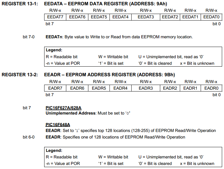
The first register is the location for the actual data to be stored or read from the EEPROM.
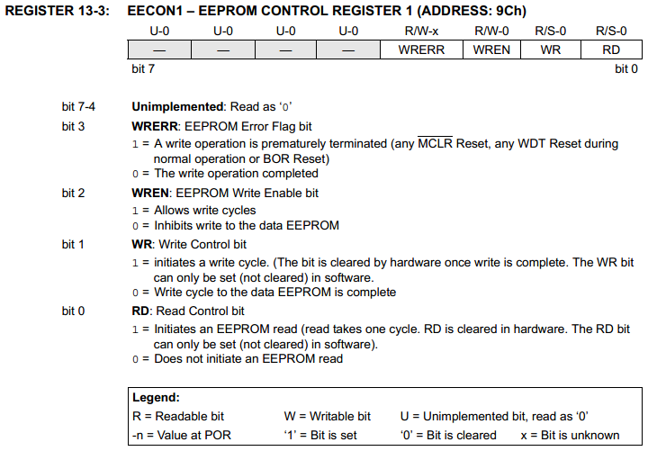
The second register is the EEPROM address, for the 16F628A there are only a maximum of 128 bytes of storage so the eighth bit must be left zero.
Some chips such as that I will use in the next project will have an additional two registers, one allowing 14-bit data and the other to allow a 13-bit address, there is also the capability of reading and writing the main program memory.
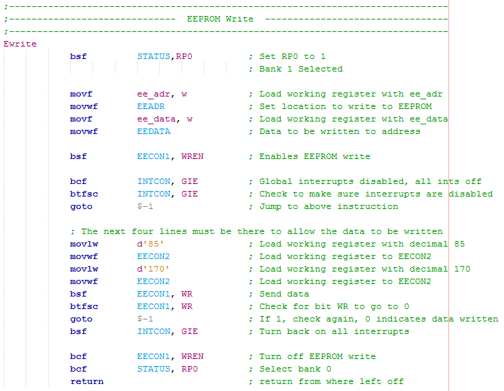
This is the control register which is pretty standard throughout the microcontroller range, there is sometimes an extra control bit to differ between dealing with the EEPROM or the Program Memory.
WRERR - This is if the chip has been reset while the EEPROM is in the process of being written, the bit will flag as logic 1. Normally this bit can be completely ignored.
WREN - When logic 1 this will allow data to be written to the EEPROM.
WR - When set to logic 1 this bit will initiate the write sequence of the data to the EEPROM, when the process has been completed this bit will set itself back to 0.
RD - When set to logic 1 it will read the selected EEPROM address register and place the contents in the EEDATA.
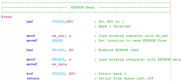
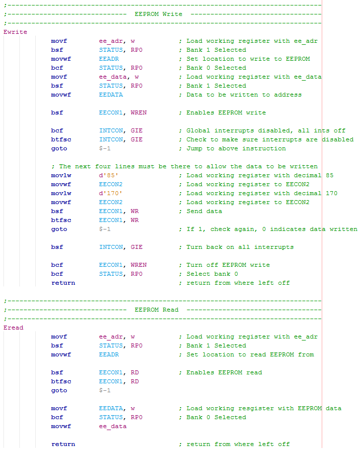
The one register that isn't readable is the "EECON2" register as this is associated with the write sequence. In the write sequence the numbers "55" and "AA" in hex or "85" and "170" in decimal must be sent to the "EECON2" register in order for the data to be written, this is a must. The following program shows how EEPROM is to be written to a location.
Only two parts of data are needed in order to write data to EEPROM, an address and the data to be saved. Since there is a maximum of 128 bytes of EEPROM data the address must be in the range of 0 - 127.
This sequence is pretty much standard throughout the 16 series of microcontrollers, the only difference is that the registers may be in different banks so care must be taken when choosing a different chip,
Notice that the "WR" bit of the "EECON1" register must be checked before continuing, this is just to ensure the EEPROM has finished writing as this can take a number of clock cycles, infact it takes around 5ms.
Apart from writing the EEPROM to a location it can also be read from a location, the code is much more simple as shown below. Again an address must be chosen to read the EEPROM from, the EEPROM is read and loaded into the variable "ee_data".
The EEPROM can be read in one clock cycle and therefore does not need to loop around to check, although as a precaution it is good practice to check the "RD" bit has cleared before moving on.
Note that in some chips you may need to swap between banks as the registers may be in a different location.
One other thing to note which may not always be clear is bank selecting or when to do so. It's pretty obvious where the banks are for the the special function registers but it's easy to forget what bank the variables are in. Since I specified the start of the variables to be at h'20' then this means they are located in bank 0, so the two snippets of program above would not work unless these variables were in fact in bank 1 and since we are selecting bank 1 before we do the read / write process then we would be selecting a non-existant RAM address. The two programs above are just generic, these are the parts that I paste into other programs, no point re-writing something every time.
For the above snippets the only difference is that the variable that is in bank 0 zero is to be loaded into the working register first, then bank 1 is selected before it is to be placed into the file register.
To load the next variable to a file register I first must place it back into bank 0, then the same process applies.
Another shortcut is to write "banksel EEADR" which tells the status register to select the bank that "EEADR" is in, this is useful as you then know why you are changing the bank.
Note that "banksel" is not an instruction, it is a directive that tells the software to write two bit lines to control "RP0" and "RP1". So when using this directive it is infact using two instructions, in most cases it does result in using more memory.
Referring to the datasheet when a bank select is necessary can save time instead of placing the "banksel" command in front of everything as not only does it look messy but it takes up valuable program memory and time.
The same process is in the EEPROM read program, in the start it loads the address location and then in the end it retrieves the data from that location.
I don't often use the "banksel" command but it really is a good idea for trouble shooting problems, especially if someone else is reading your program.
I do find it to sometimes be very difficult to follow another program, one I have not written myself. I have tried my best to lay out the program with plenty of titles to try and make it easy to follow, the EEPROM part has literally been cut and pasted so it shouldn't be all that difficult to add into your own program. To my program, if the star button is to be pressed it compares what's in the variables with what's in the EEPROM, there is nothing saved in EEPROM and nothing into the keypad, zero and zero match and the LCD states "correct password". If hash button is pressed then it would save a new password. An LCD will display all of the messages such as, "enter password", "password correct", "password incorrect", etc...
In the next chapter I will write in a couple more routines that will not allow a new password to be set unless the original is entered first, it will also allow the control of external outputs such as an electronic lock. This chip has all of it pins in use so the next chapter will introduce a bigger chip, this also introduces what to look out for as memory organisation will most likely be different. Other differences are the analogue reading capability, the extra program memory space along with a slightly different procedure with reading and writing EEPROM.
Below is the program and a link to the right - Program

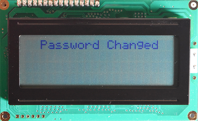
The layout on breadboard is exactly the same as that in the last project, here is another picture of the additional display command when the password has been reset.
The project is now getting a little more complex but the keypad and the LCD have used up all of the available pins on the chip. The next project is to copy this program to a different chip as well as having an external output to indicate that the code is unlocked, it could be used to control an electronic lock.
Hello, if you have enjoyed reading this project, have taken an interest in another or want me to progress one further then please consider donating or even sponsoring a small amount every month, for more information on why you may like to help me out then follow the sponsor link to the left. Otherwise you can donate any amount with the link below, thank you!