Electric Supercharger Version 1
This is the idea that I can use an electric motor to power a supercharger to force induct a car giving it more torque and power. I saw what was described as an electric supercharger on a car tuning website that was powered by a little 15W motor, it was basically a small extractor fan, the price was quite high and it boasted performance but I was very skeptical. I know that a mechanical supercharger will take around 25% of the engine power to run it, say for example the car I'm driving at the moment, if the supercharger took it to 200bhp that would require 50bhp to power it. I know a lot of mechanical power is lost in a supercharger but a relatively efficient turbo still requires a lot of power from the exhaust, certainly a lot more than 15W. (Around 746W to 1hp).
So a quick worked example to see what kind of mechanical power I would need assuming the supercharger is 100% efficient I would do something like calculate the mass of air required at a certain pressure to produce a certain amount of engine power. Take an average 2L engine producing probably around 140bhp, a turbo with a boost of around 8psi would take this to 200bhp (ish). To make 200bhp you would need around 9kg of air per minute. 9kg of air is about 7.5 cubic metres per minute, lots of calculations, and it would need 10kW of power. The fact that I need such a large amount of power makes me realise that these fans probably restrict flow and drop power.
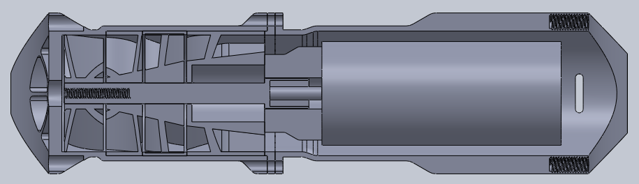
The idea is that I will make a turbofan assembly that will hopefully be capable of around 10psi of boost and be modular so I can add multiple units to increase power, each unit would be around 3kW in power. The turbo would literally need a boost button because even 3kW at 12V will equal 250Amps which is more than an alternator could provide continuously. The idea is to make the whole assembly out of metal but utilising 3D printing of plastic if the material is rugged enough. If I fail to get the right design or I'm unable to make certain parts then I will likely end the project and start a new one by modifying an existing turbo, with that I at least know that the blade design works, the only issue may be the limited motor speed, I don't want gearboxes running at 100,000rpm, a lot of heat is generated.
12 June 2017 - I started this project page. I like the idea of using a turbofan to provide boost, it means that I can make the units modular, it is pretty much impossible to use parallel turbo's since there's no way of balancing them, my electric units will spin at the same speed and therefore their pressures should balance. I know that the faster an impeller can spin the more efficient it is, so the first step was to find a suitable motor. After a lot of searching I found a motor on a chinese trading website, the motor of choice was intended for RC boats. The motor I found was 4000W, 50000rpm, 36V at 110A with a footprint of 40mm diameter and 90mm long. It's really amazing to think that such a large amount of power can be put through a motor this size, it is brushless and requires an ESC in order to run it, I intend on making my own ESC.
I bought some aluminium to make the housing for both the motor and the fan blades. I set out to find some CAM software to machine the impeller blades but I quickly realised that this would be difficult, so I gave up on the idea of metal blades and opted to go for plastic which I will 3D print. This is my major concern with the project, will the plastic ones handle engine bay temperatures and be strong enough.
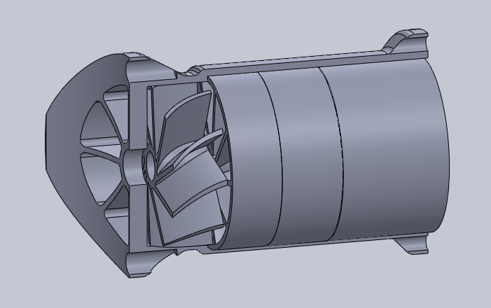
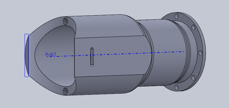
I mocked up some kind of design on the CAD software, this first one will use hoses to connect the ends, my concern is squashing them.
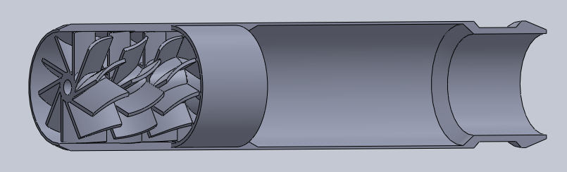
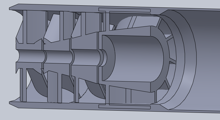
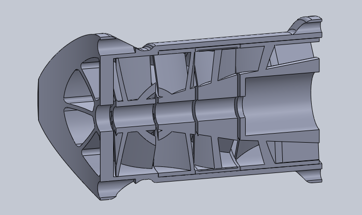
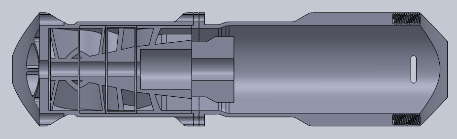
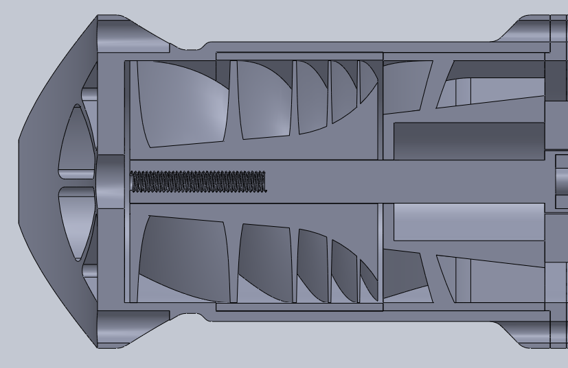
No math went into the design of the blades, I just figured that mimicking the size of a 200bhp size turbo impeller would get me somewhere in the ball park at these lower speeds. The blades are arranged much like those in a jet turbine, the first blade spins directing air in one direction, the second blades are opposite angled and stationary which directs the air in the opposite direction for the third blade to catch it and so on. The area through the blades gets progressively smaller with the intention of compressing the air, the area compression ratio for this first trial was 1.5 : 1.
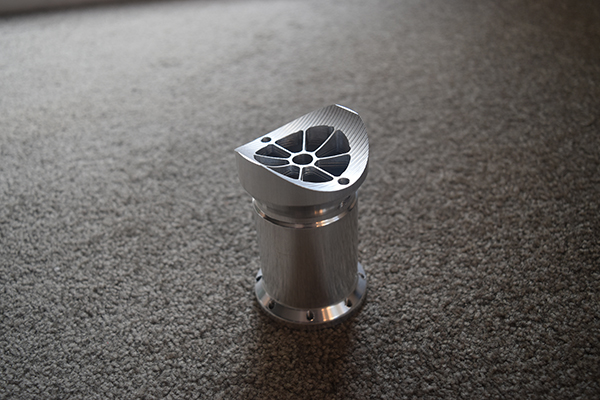
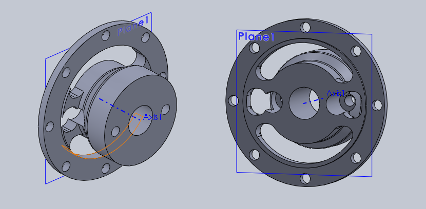
17 June 2017 - I started a new design for the blade housing, the face as a conic along with two bolt holes, this will butt up perpendicular to the intake tube. The inertia of the motor starting and stopping could have caused the housing to spin over time in the previous design, this cannot happen now.
The final compressor blade in the assembly will house some ball bearings, I really don't think the force would be that great to damage the motor bearings but it also allows me to add a flexible coupling just incase parts don't align perfectly.
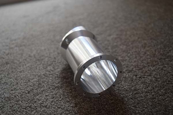
Another screen shot of the housing.
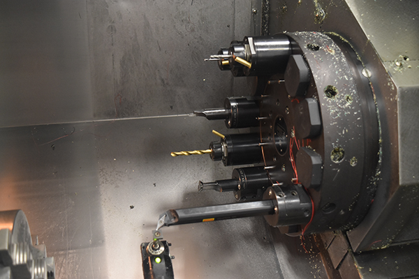
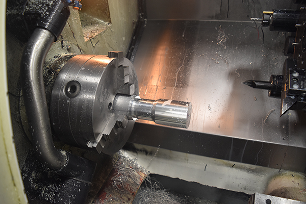
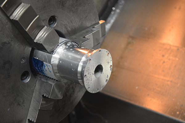
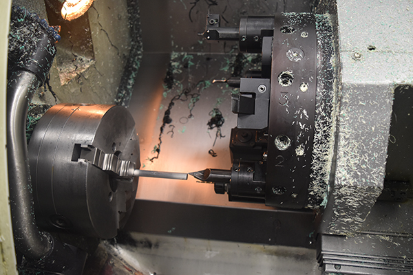
I'm allowed to machine my own parts on the works CNC lathe which has a live tooling capability, I know that this particular design on a manual machine from prior experience would be very difficult and time consuming. The long boring bar is to turn the outside contour, rigidity may be an issue.
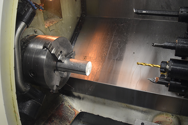
Rigidity was indeed an issue so I chose to chop the bar down, this slightly improved the finish but it was still unacceptable. The boring bar was intended for inside turning meaning it would have a clearance angle, I placed the bar in the miller and flattened the tip holder profile. The profile turned perfectly, I later found a different VDI holder that would hold a regular turning tool, that proved to be the safest option and the most rigid.
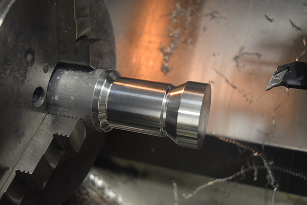
The lathe has a Z, X and C axis meaning that most milling procedures would be impossible and most would be very difficult without a dedicated CAM software. I found that the Siemens control I was using had the capability to simulate a Y-axis for milling. I programmed a a circular arc profile and used a macro to increment the Y-axis, around 70 passes and the face conic was complete, this was milled axially, most radial operations are impossible on a lathe.
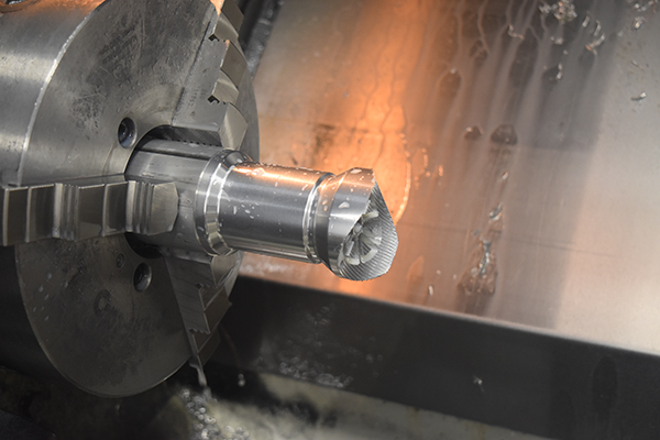
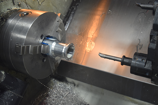
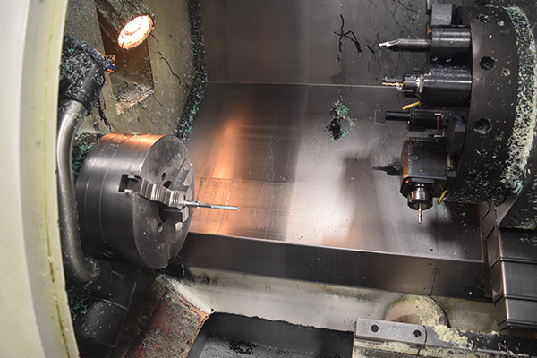
The part was flipped in the chuck to machine the opposite side, I originally programmed a tip to draw a score line so I could align it's angle. Using a drill and then a boring bar I machined the inside, a series of holes were drilled which will be used later to secure the motor housing.

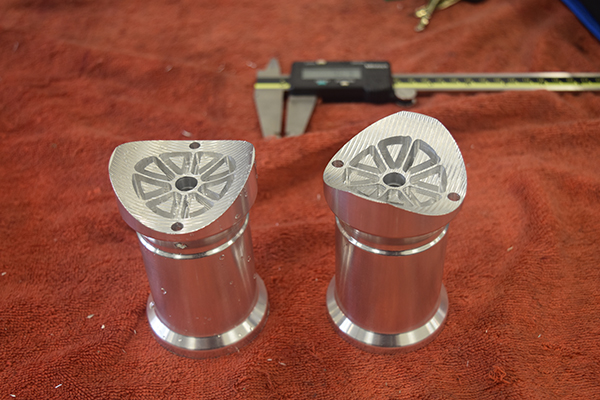
I chose to machine two parts, it is likely that I will only fit one of these superchargers but machining multiple parts is wise due to the time it takes to setup the part and if I make any mistakes.
26 June 2017 - I finally got my motor through the post today so I could get on with designing the project again. The first thing I did was mock up some kind of mount to fit the motor.
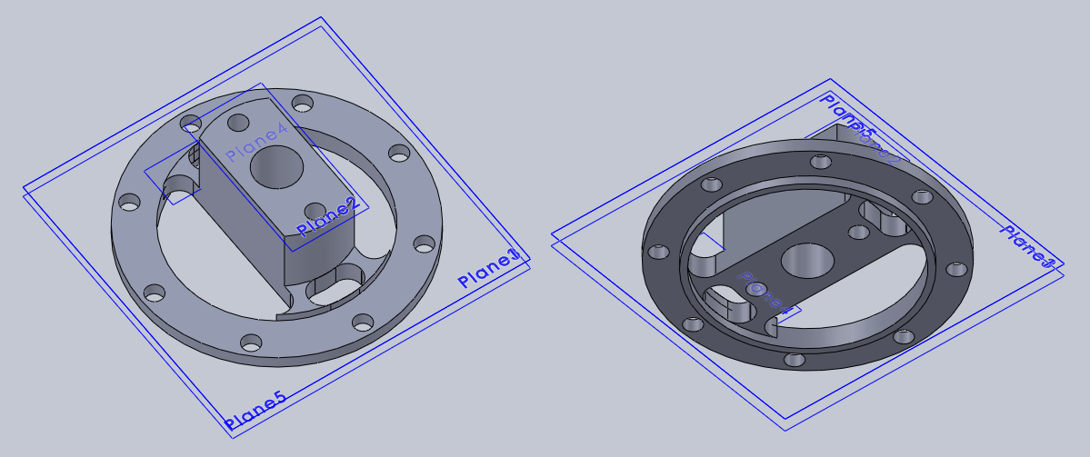
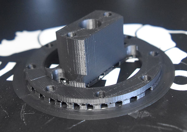
I though that it would be best to first 3D print the part in plastic to ensure it would fit against my motor.
I did some further modifying to give a better airflow around the motor, in this design the compressed air will pass by the motor casing to help cool it down.
Over the next few days I machined these parts in my lunch time at work meaning that I didn't take any pictures of the machining process.
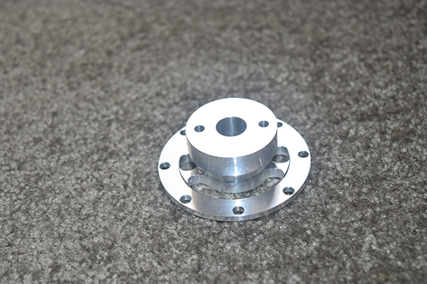
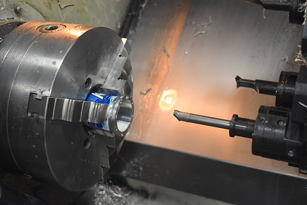
01 July 2017 - It was finally time to machine the motor housing.
The housing will help to cool the motor by letting air pass inside between the motor housing and the bore. The outside has a flat that will be used to conduct heat from the MOSFET's, these are used to control the motor.
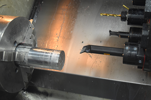
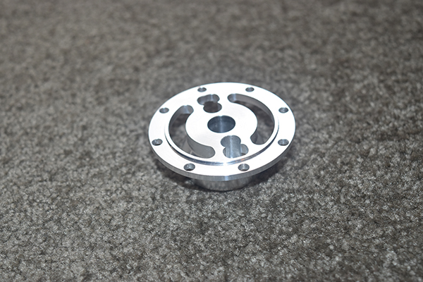
The tool I found worked perfectly, no resonance and a perfect finish. Another conic was milled into the face of the billet, a smaller radius this time as the outlet can be smaller, higher pressure, the higher the flow.

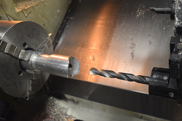
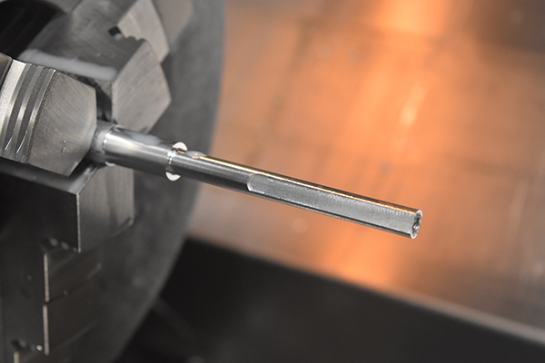
I found a drill to do the full length, for scale the bar I used was 2.5", it drilled out pretty much perfect compared to the cheaper drills I had been using previously. The the holes were drilled for the securing bolts and the part flipped in the chuck. On the other side the holes were drilled for the bolts what will secure the assembly to the blade housing.
The inside was roughed out with a smaller boring bar, the part was flipped in the chuck to machine the other side. I then finished off the inside with the long boring bar that I had used previously as an outside turning tool. I could not mill the flats in the lathe for the MOSFET's unless I decided to get a fly cutter, which of course I didn't.
8 July 2017 - I finally managed to machine all of the major metal parts, the last part I finished today was the flat on the motor housing.
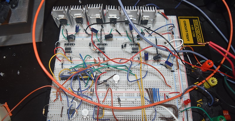
I thought that I should proceed with making the inverter to drive the motor, this proved problematic. The first issue I encountered was that my signal generator would not give out a continuous signal, so the motor would run erratic which led me to use a simple 555 timer instead. The back emf from the motor fried my voltage regulators for the control circuit so I had to battery power this part. I got the motor to run and the pwm circuit to control the current but the emf killed one of my MOSFET's, I should have used a snubber circuit. The breadboard could only take a few amps, I really didn't feel like making the circuit board either so instead stole the ESC from my grappling gun project. As much as I would like to build my own circuit the cost of an ESC wouldn't be too much, I would at least have the reliability then.
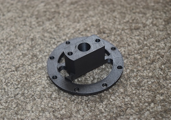
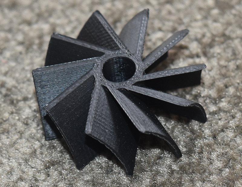
9 July 2017 - I thought that I should now concentrate on making the impellers, this one below is something I made before I started the project to make sure I could 3D print one. This example was in ABS, it came out really good but I figured it was too small for my application.
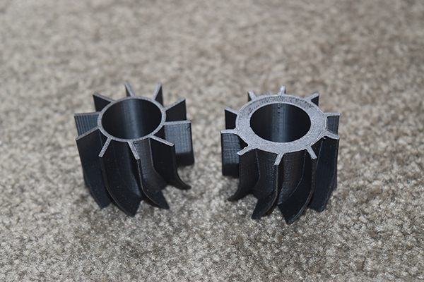
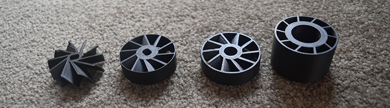
Over a few days I played around with different designs and getting the prints to be perfect. The first image on the left shows two designs of bearing carriers that I made, I realised the direction of the blades was wrong and that the vanes did not close up enough to boost pressure. The impellers on the right we just lots of trials to adjust for shrinkage and blade rigidity.
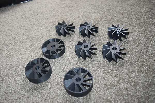
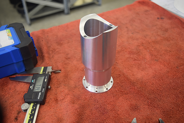
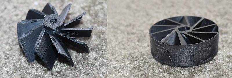
15 July 2017 - I finally made what I believed would be the right designs of impellers, my concern was that the first impeller blades would open out and catch the housing, the third impeller blade (second from left in picture), I chose to place a ring around the outside for strength, this is so I could have some kind of a comparison. Finally I designed a key so that the blades could secure to a shaft, compression pressure alone probably wouldn't have stopped them from spinning.
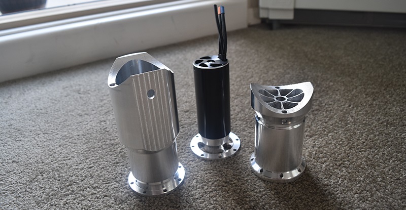
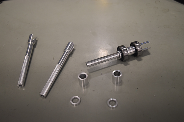
22 July 2017 - I chose to make the drive shaft out of aluminium, since there wouldn't be a huge load I figured it wouldn't matter. (My very messy machine, made sense to clean up after machining metal).
The finished results. The bearings had to be press fit, steel on aluminium is never a great idea as aluminium is a sticky metal, it took a lot of force.
The drive shaft and bearings were pressed into the fourth impeller and then all of the blades were pushed into the shaft.
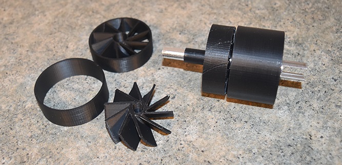
I assembled it all together and ran the motor, all of the blades were a pretty tight fit so I chose not to use a screw. The first blade managed to push itself off the shaft meaning there was definitely pressure produced.
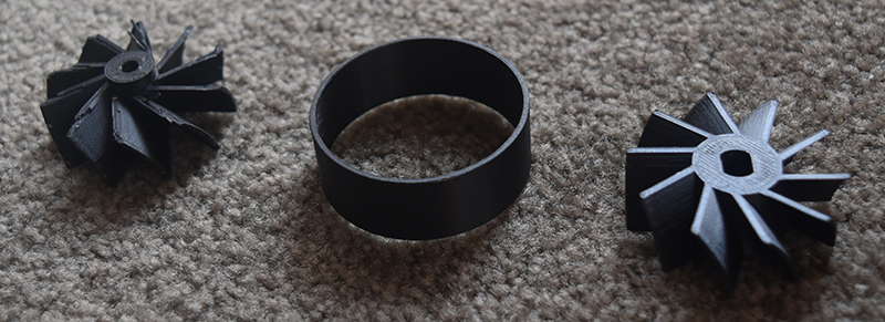
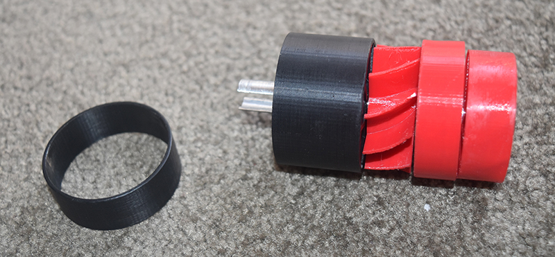
I chose to reprint the first impeller blade and the third. The first (used on the left) had an extra washer printed into the design. The third impeller originally had a ring around it's outer edge, I figured air would pass by so I eliminated it from the design. The middle is a spacer ring in which the third impeller will spin inside of.
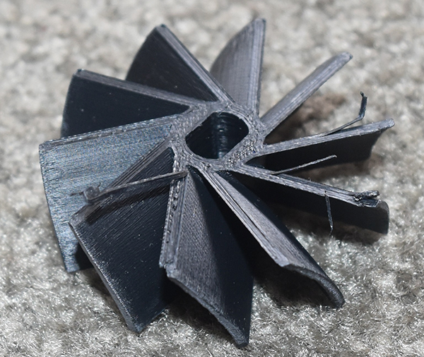
The first impeller as shown below decided to open out and jam which resulted in it destroying itself. I reprinted it with a cylinder around the outside, this would strengthen it but also allow air to pass over the top. The blade had to be made to a very tight tolerance to stop the air leaking past which is why there is some scuffing, this resulted in a very loud high pitched noise.
23 July 2017 - I got a new 3D printing material, PETG which bonds a lot better than ABS does and does not warp. I again ran the motor which resulted in a very high pitched noise, very little pressure was produced, literally only about 2psi which clearly shows that air is bypassing the blades or I don't have enough area reduction through the stages.
At this point in the project I'm seriously considering modifying an existing turbo, perhaps this can be a side project. For now I want to get some kind of a blade design to work, the airflow is not an issue because I can scale the whole thing up, the issue is pressure and I want to achieve around 8 psi if possible. The current design I have is the one below.
I chose to use a single impeller to spin, this way hopefully there should be very little air bypassing and the compression ratio is a lot higher. The blades at the end are very steep which seems to be an issue with my new 3D printing material, it could also be an issue will my printer cooling, so either the material has to change and / or I have to supply additional print cooling.
Hello, if you have enjoyed reading this project, have taken an interest in another or want me to progress one further then please consider donating or even sponsoring a small amount every month, for more information on why you may like to help me out then follow the sponsor link to the left. Otherwise you can donate any amount with the link below, thank you!