Precision Hydraulic Forging Press
I have always had an interest in working with metal, but I find working hot metal to be a magical process. I very first built a foundry when I was 15 to melt and cast aluminium. I later tried to use that foundry as a forge in order to heat and shape metal, that was not so successful. It was that project that led me to invest a huge amount of time into building an induction heating unit. That original project was logged on my computer and the hard-drive failed, and that's the reason I started this website.
I totally gave up on the idea and never thought I'd be visiting anything related to it again. Well after doing a little bit of research I found that an entry into forging is the use of an hydraulic press instead of the more traditional power hammer. The fact is that manually beating metal is a very intensive and noisy process. The power hammer was invented to take out most of this work, in fact, it allowed much higher forces and larger pieces to be forged. The power hammer is often a very loud piece of equipment and have mostly become replaced with hydraulic systems.
A hydraulic system can achieve a much higher force for its size than a hammer ever could. They started to become very popular with the amateur blacksmiths since they are much quieter and very powerful for their size. I started looking around into all different designs and decided that I wanted to build my own. There are many reasons for doing so, and that is not only just for personal interest as most of my other projects are. I do believe I could make a smaller unit capable of faster movements while using far less power, and also making it a precision unit.
Like all of my projects I tend to think them over for a few days, see what parts I can source and make some random doodles. Here is an example of the first design basing on a 4 inch hydraulic cylinder capable of 20 tonne, this is a common starting pressure, and a very capable one at that. As a reference of size the pillars are 2 inch in diameter.
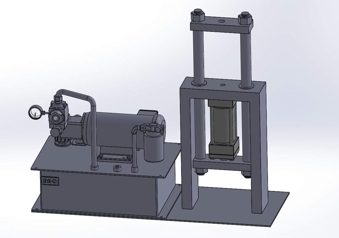
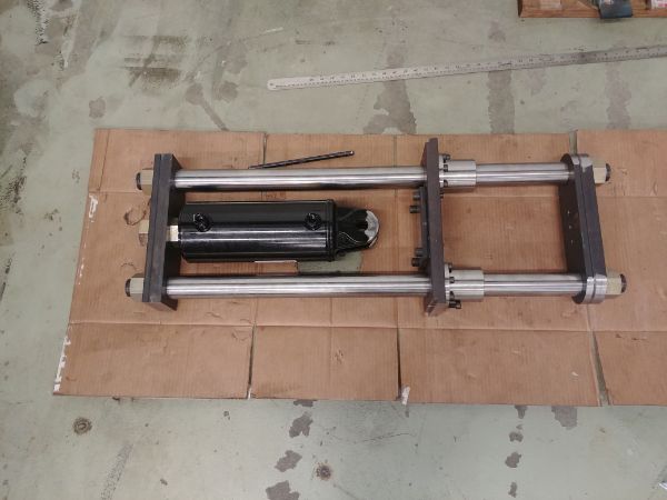
The idea of throwing together a simple design like that above is to gain an idea of what components may be needed and a representation of the finished product. This design is completely different to all those currently on the market, but it is very similar in design to a moulding press. The idea with this design is that it requires less load-bearing parts, literally the pillars and the top and bottom plates. The force will be to the back of the cylinder and between the top plate, this minimises stress. When a pillar is compressed it is more likely to deflect in a random direction, this may only be minimal but will increase wear on bushes. When a pillar is stretched it will try to straighten out and therefore remain parallel.
The top and bottom plates need to be thick enough so they do not deflect, but this would be the same with any press. In this case if they were to bend then it would pull the pillars closer to each other, and of course increase wear on the bushing. Now the bushings on this press can be off-the-shelf items meaning that if they wear, they can be replaced easily. The pillars are made from precision ground 4140 which are strong and resistant to wear, especially if I have them chrome plated. I see a lot of presses having no surfaces designed to be replaceable, or even be made from wear resistant materials. Many of them have wear points against the frame which are low-carbon mild steel, once they wear the whole press frame is scrap.
This comes to the point of precision. If I use precision ground pillars and bushes then I can maintain a tight tolerance. The idea is that when something is pressed, especially with regard to dies, they will not move in my press. If dies and forms move around then they are more prone to damage and high amounts of wear. The competitors are quite loose in comparison as tightening tolerances will cause high amounts of wear, also tight tolerances are difficult on weld fabricated parts. I not only allow my press to be serviceable, I allow critical tolerances to be achieved.
The hydraulic cylinder will be a standard one, no difference to the others on the market. Keeping to a standard item and pressure helps to keep the cost down, it also allows off-the-shelf parts from any hydraulic dealer to be used. What will revolutionise my design is the way the hydraulic system works, it also took a lot of thought. These hydraulic presses need to be able to move quickly to the metal and then be able to achieve high pressures. In hydraulic systems you have slow - high pressure and fast - low pressure. The only way to have a high pressure and fast system is to use a lot of power.
Nearly all modern hydraulic power packs will use a 2-stage pump. One pump has a high flow rate with normally a maximum pressure of 600psi and the other pump has a low flow rate capable of up to 3000psi. These units are cheap but quite flawed in operation. So once a pressure of 600psi is hit on the high flowing pump it will then vent through a relief valve, the slower pump then takes over the effort. The big issue is that when this threshold is hit the pump is using for example 2HP of power, after 600psi this high flowing pump is doing nothing but drawing power. The second pump will then consume another 2HP at full rate which leads to an overall usage of 4HP.
The standard 110V wall socket (I'm in North America) can only supply 2HP maximum, there is of course 220V sockets that support 4HP, but that is not common unless specifically wired in, especially home workshops. If the above example was dropped down to a 2HP drive motor then we lose out on speed. A lot of these available presses offer both options, but again this is not a very efficient system. I chose to drive two separate pumps with a single 2HP motor, the difference is a pressure transducer detects when the pressure hits a certain threshold and then opens a valve to vent the pump. Since the pump is vented it will draw little power, the remaining can then be used to drive the high pressure pump. A great benefit to using two pumps is that I can size the high volume pump to operate an an even lower pressure, it doesn't have to do any work after all.
So overall I can use half the size motor to achieve faster speeds, the same pressure while being able to use the readily available 110V wall socket. It will require a lot more pipe work, electronic valves and sensors. The design may be a lot more complicated but it will perform better and run more efficiently. I will also note that because I'm using electronics to control the system that I can do a lot more than simple mechanical type valves, as I'll explain much further on.
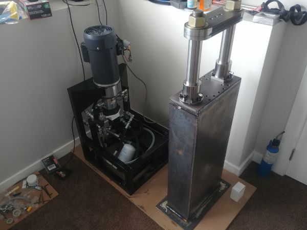
The very last attribute to this press is that it will be in a much smaller package while exceeding performance. The hydraulic unit will be separable from the press itself, this serves two purposes. The unit can be transported easily and will fit onto a standard size pallet. The hydraulic unit can also be located far away from the press if space is a concern. The press itself will bolt onto the hydraulic unit in a compact form.
The Improved Design
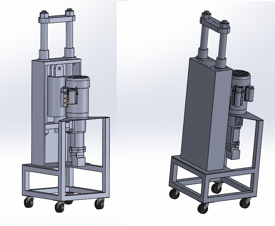
I have improved the design based on parts I can source, there is of course a lot not on here. I often work the rest out in my head as I go along since large assemblies can be hard on my computer. I also managed to reduce the thickness of the frame since it only has to bear the weight of the unit, dropping the weight reduces cost and increases portability.
Building the Press
I didn't want to spend too much time designing this thing, I want to build it. I will say however that I designed the parts to require minimal amounts of CNC work as possible, it can even be made on manual machines. The reason is this prototype is for myself and will not be for profit of any kind, plus I'm using machines in my lunch break that I do not own. If there is interest with intent to sell then I will either invest in basic machinery, get permission, contract the work out or possibly even hire machinery. Time will tell.
The actual build process was in a bit of a scattered mess since I had to work this around my lunch breaks without disturbing actual work. I managed to do all of the machining in 5 hours (1 hour each day), including setting up, programming and setting down. All of the threaded holes, welding and assembly was done after hours since those carry little risk. It's also remembering to take pictures when you're in a rush.
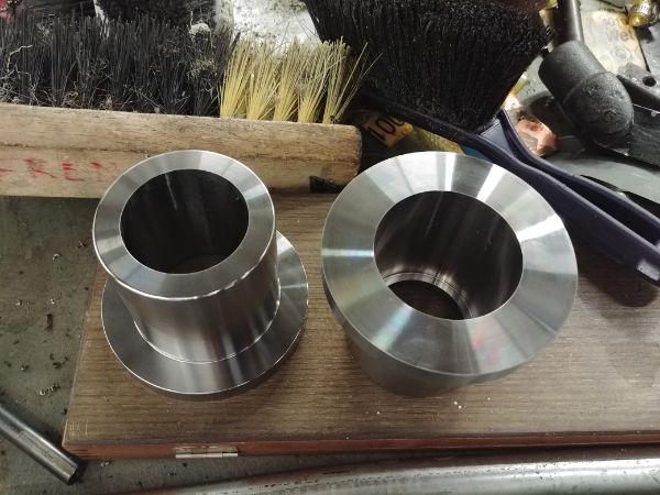
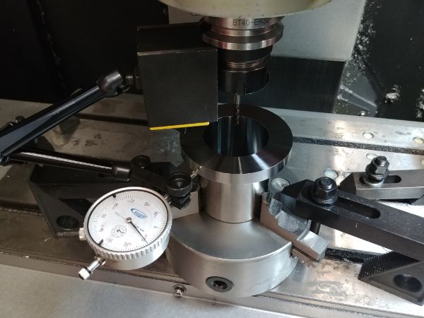
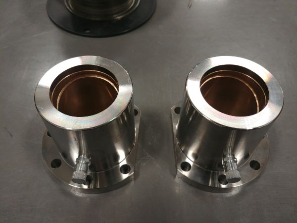
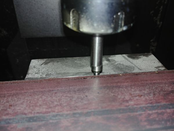
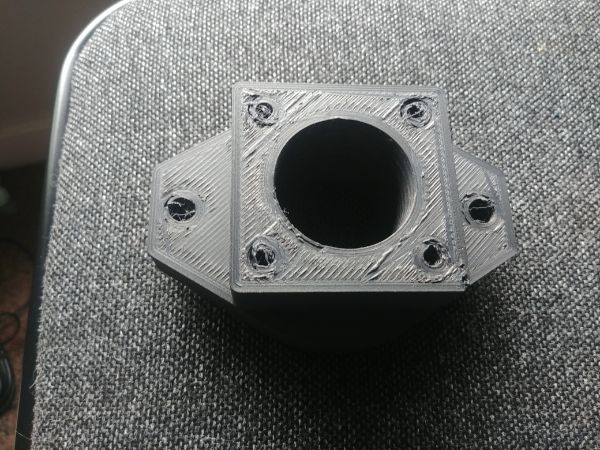
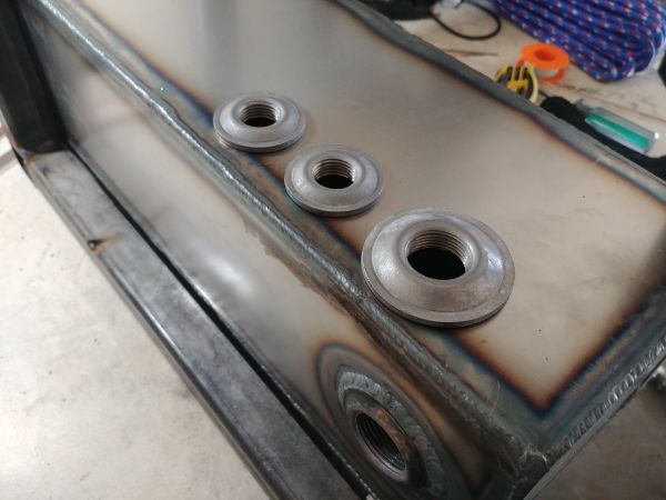
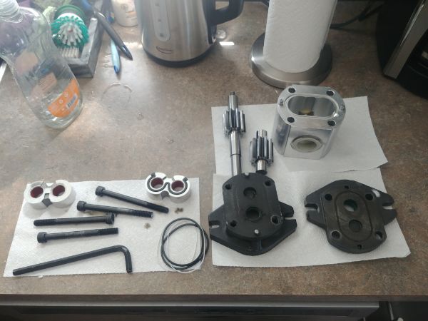
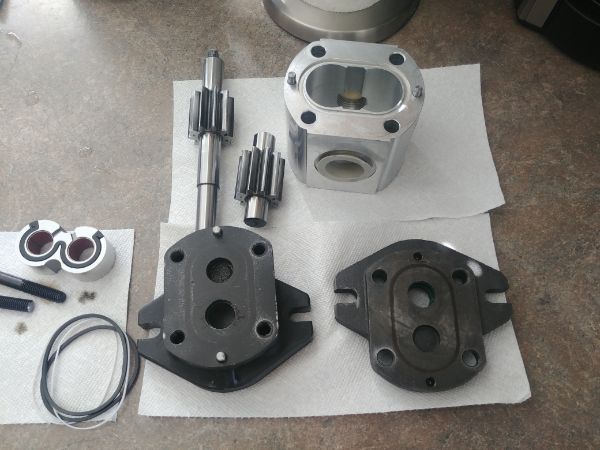
These first parts are carries for the bronze bushes which are made from 4140HT steel. The internal bore was made to a 1 thou tolerance since the bushes would be pressed inside, however the design also determines that a press fit is not required. I used a basic CNC lathe to make this part and then placed it in the CNC mill to do the next operations.
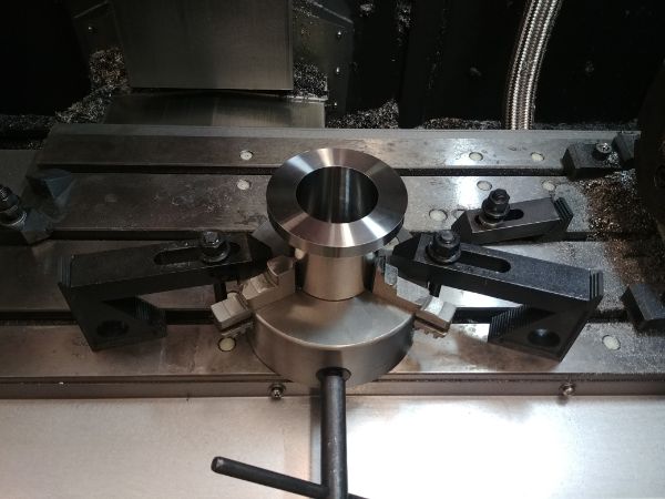
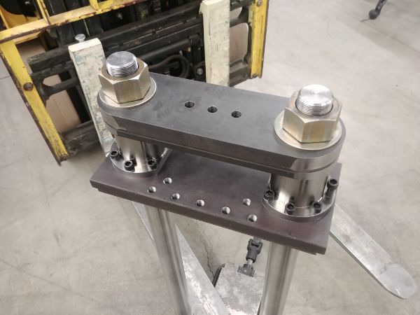
I clocked it to find the centre point and then generated a tool path using CAM software. A flat milled to give extra room in the actual pressing area and then a series of seven holes. The holes are used to bolt these carries to the top frame plate, the bolts only load carrying is the friction between the bush and the pillar shaft.
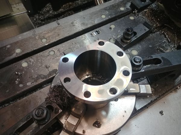
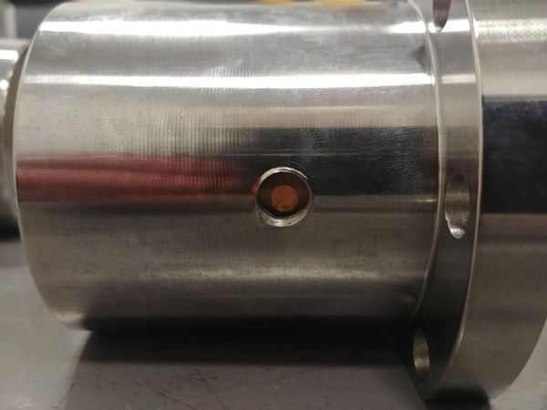
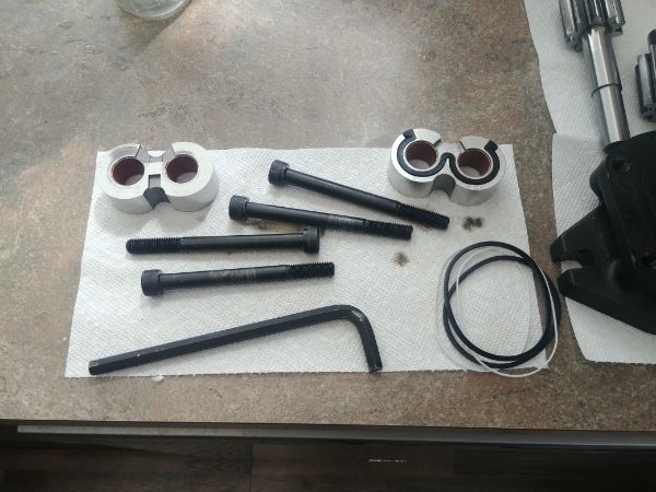
The carriers were heated to 200 deg C, which off the top of my head will make them expand around 3 thou. The bronze bushes were cooled to minus 15 deg C, that should make them shrink almost 1 thou. The bronze bushes dropped in the carriers by gravity, no pressing was required. They are made with a 2 to 3 thou interference fit, they are in there solid. I forgot to take pictures but I did drill and tap a holes in each side of the carriers for a grease nipple. These bushes have grooves cut inside of them to retain some grease, it was so much easier buying an off-the-shelf item instead of making these.
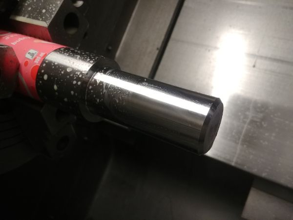
As a reference of size these carriers are just over three inches tall, they came out perfect. Next was to work on the pillars, these would only require a thread on each end so I started with a test piece.
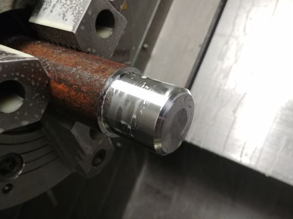
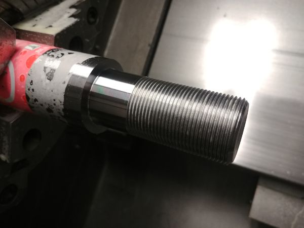
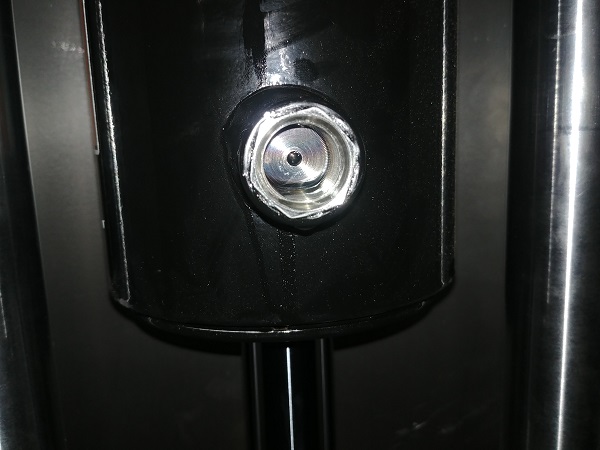
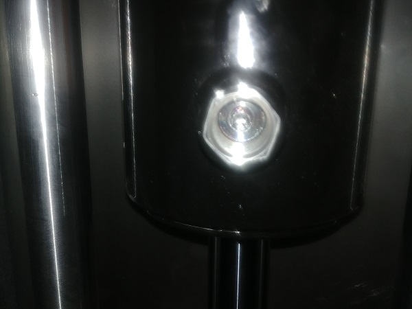
I used the G76 threading cycle which infeeds the insert at an angle to reduce cutting pressure and increase insert life, this is pretty standard stuff. The test thread came out looking great, it is a 1.5 - 12TPI UNF thread. The tolerance on a thread like this is about ± 0.006" which is pretty easy to hit. I hit the middle point and found the nut to still be on the loose side, so I decided to make the actual parts a thou off top tolerance. I cut an 80" length of precision ground 4140 into two equal lengths, the bar gripped via aluminium pop can to stop it from being marked.
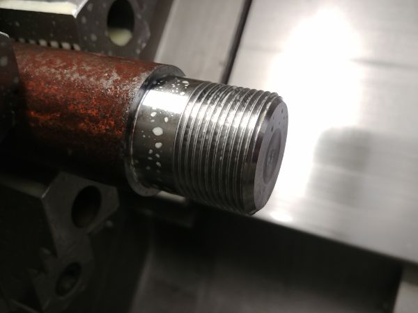
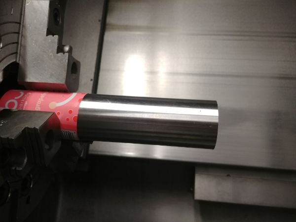
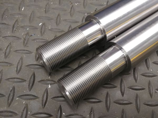
The steel turned down and threaded, these large threads are quite satisfying to make.
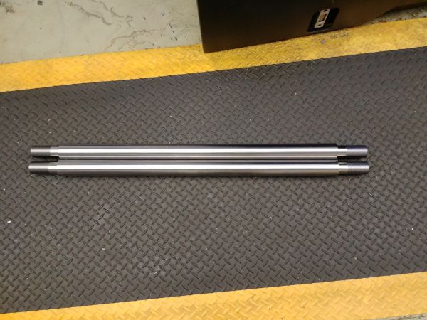
I did not have access to any measuring equipment apart from a ruler to measure these. So I did three of the threads first ensuring that I took extra metal off the completed pillar. I then placed them next to each other, squared them up and measured the difference in height. I made the adjustment in the lathe before cutting the final thread. I'm not exactly sure what the final length is, but, they are within a thou of each other. If I were to ever make a production run then I would invest in measuring equipment, but they would likely be sold in pairs anyway.
The nuts used are grade 8 which is pretty much the highest off-the-shelf grade you can get readily. These are sufficient for this application, if I really needed more strength then I would have to make them myself.
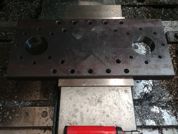
Next was to machine the top plate to the correct width, but first I clocked the vise parallel before zeroing the piece of steel itself.
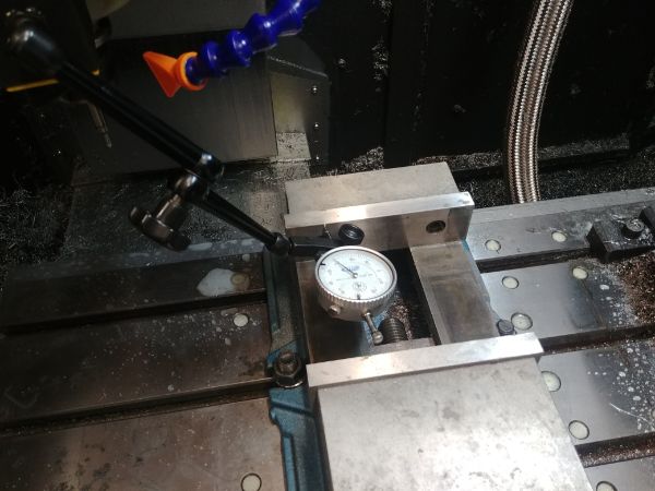
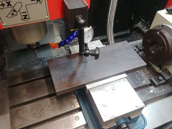
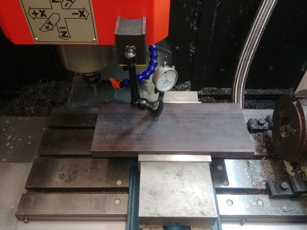
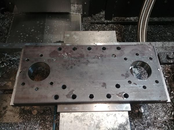
All of the holes drilled, the larger holes for the pillars to pass and some steps on each end for the frame to locate. I made sure these plates were flat to within a couple of thou in the vise itself, again if this was a production run then I would make some fixtures to hold it perfectly flat. To actually mill this flat would just be overkill, so I chose not to.
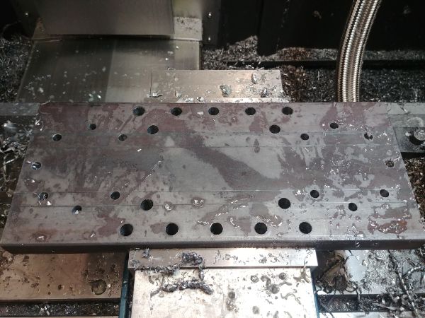
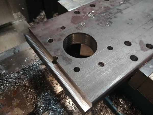
If I had not been in such a rush then I would have liked to setup the mill to do the threads, although I'm not exactly sure it could have. So by far the most consuming part was threading all of these holes by hand, again if this was a production run then I would setup a manual mill and spiral flute taps to do the work.
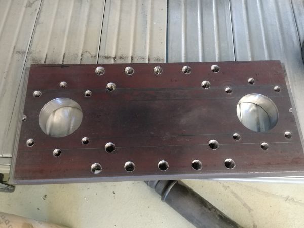
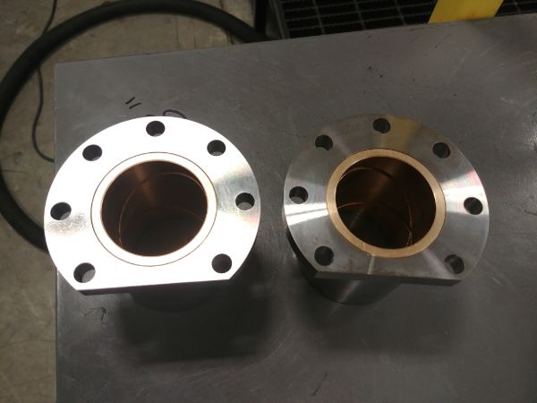
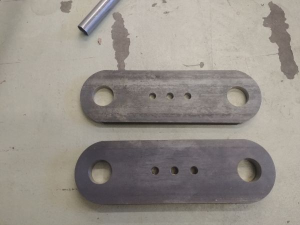
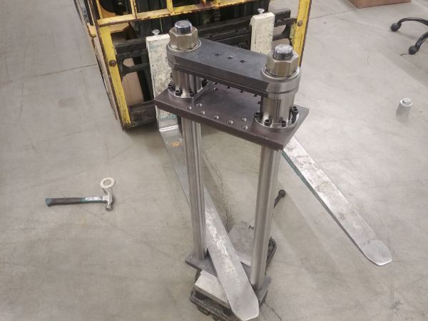
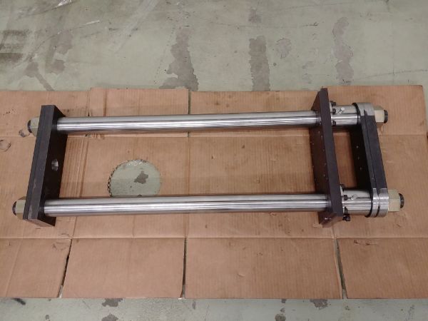
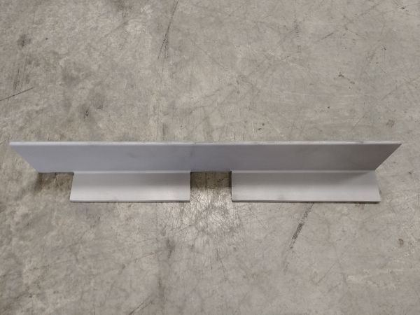
I then set to making the top and bottom plates that hold the pillars together. I wanted to make both the top and bottom out of a single piece but could not source the material in time, I thought that for a prototype two pieces would be ok. The top plates had the edges rounded to make it look prettier, the bottom ones would be hidden so the extra work was not necessary.
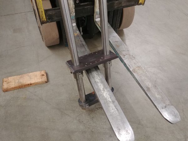
I started to do some assembly of the press but had a lot of issues with the bushings fitting over the pillars. I didn't take any pictures but I had to place the carriers in the lathe and skim a thou off the bore of the bushes. Still they were extremely tight but I had the aid of the forklift to do the hard work. The idea behind all of this is that the bushes are paired with the pillars to ensure the tightest fit possible, the first hour of operation would be done with a thin lubricant to get them to bed to each other correctly. This is something I believe will work, but I'm going on instinct.
I of course would not have access to a forklift in a production run, but then I would make some holding fixtures.
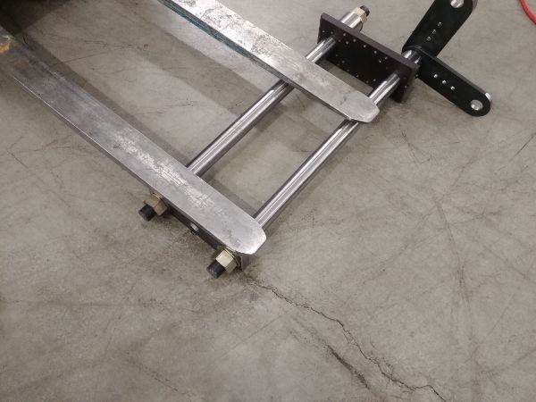
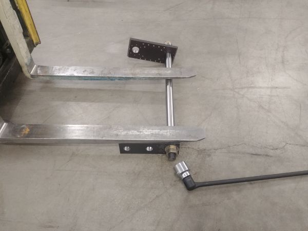
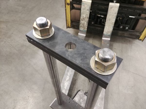
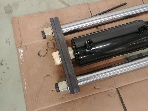
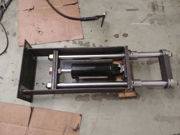
The assembly started to get heavy very fast, so using the vise and forklift made it so much easier. I used a 3ft bar to tighten all of the nuts, it would have been impossible otherwise without it.
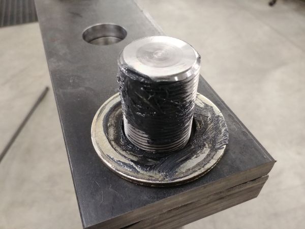
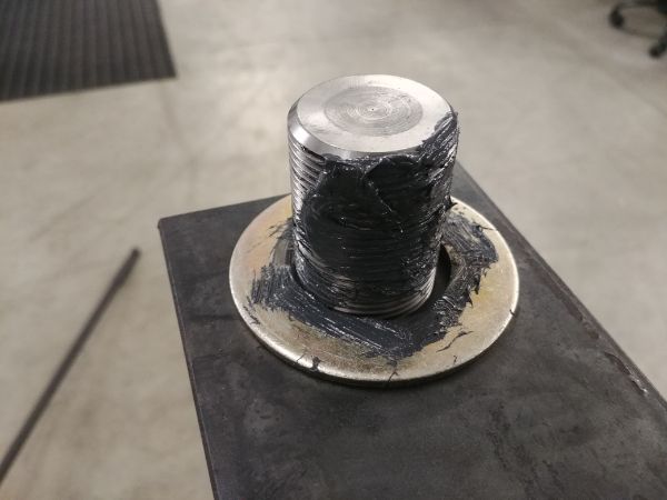
I used an anti-seize lubricant on all of the threads to ensure I would not gall them up. Also having some kind of lubricant on the thread and washer makes assembly just a little bit easier.
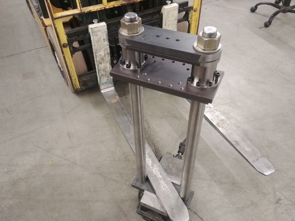
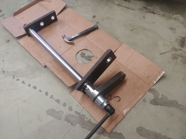
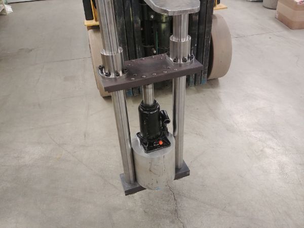
I needed to make a larger gap between the top plate and the top frame for the hydraulic ram to reach. I used the forklift and some bars to do the hard work, it required probably around 5 tonnes of effort to move it. I would invest in a puck jack to do it myself in the future, if needed.
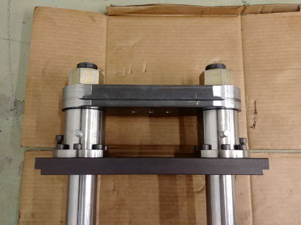
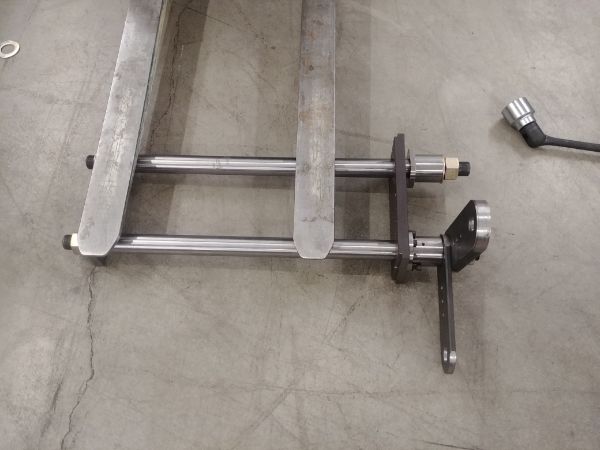
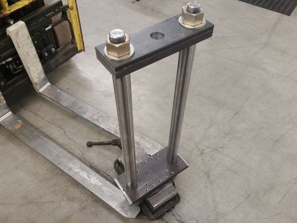
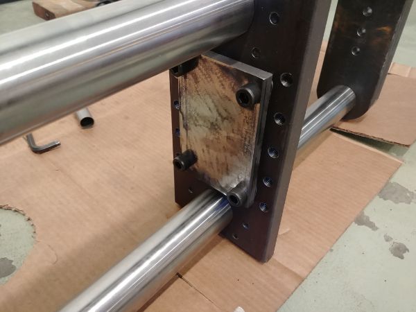
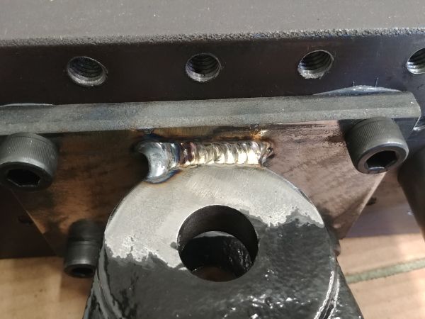
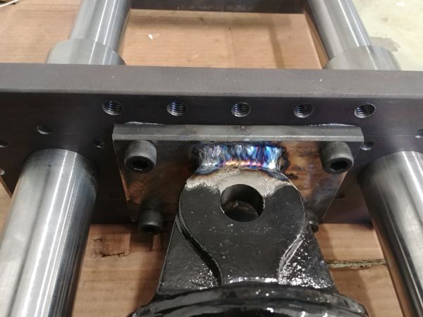
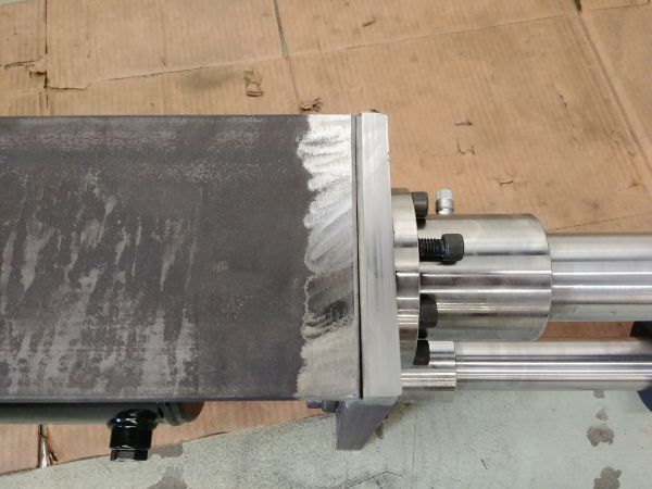
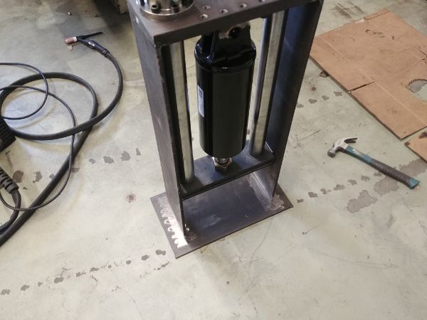
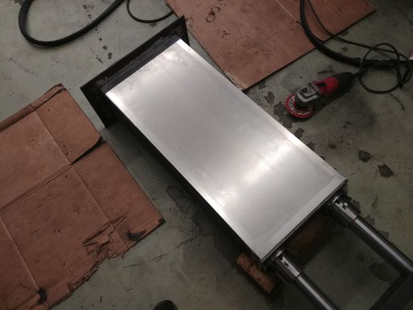
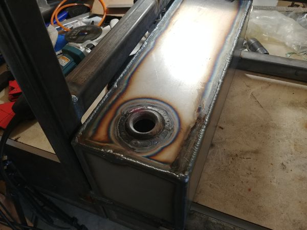
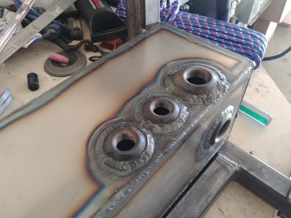
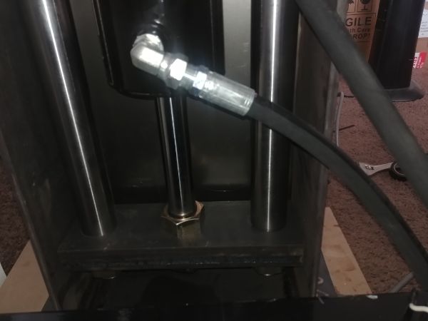
I measured the distance between each bush carrier and top plate, these would need to be even for when I weld the hydraulic cylinder in place. I was quite amazed that they were within half a thou of each other and required no adjustment. I cleaned up a plate and bolted it in place, this will serve as a bracket to weld the hydraulic cylinder to. I will add that I chose not to use the pivot as I want this setup to be as rigid as possible.
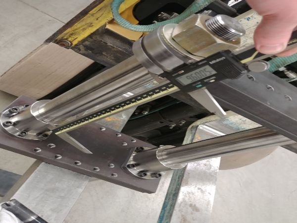
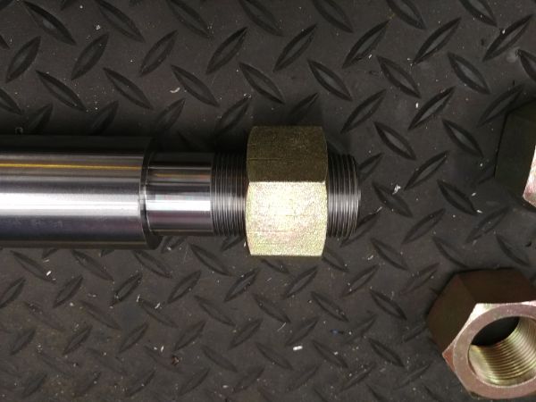
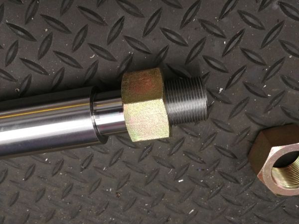
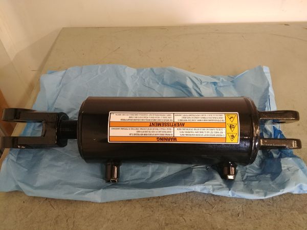
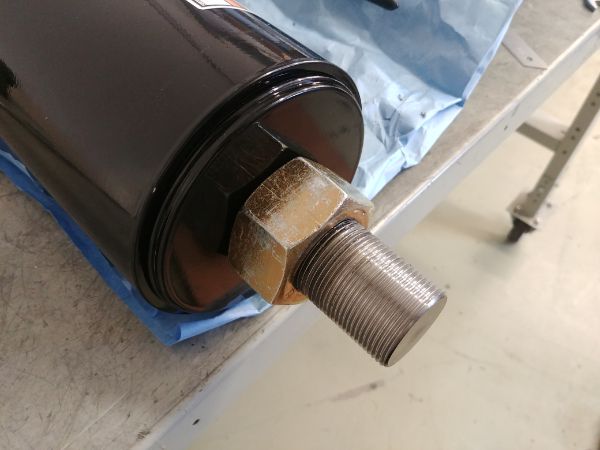
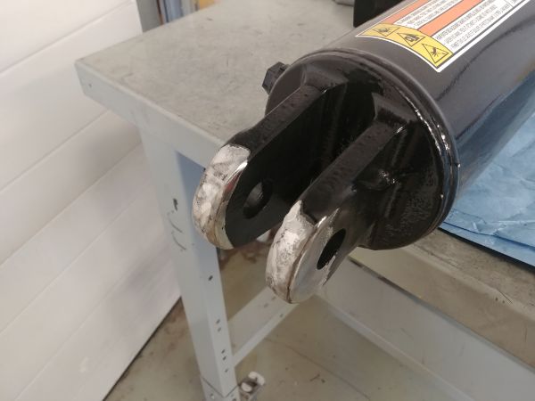
I got the hydraulic ram / cylinder from a surplus store. The bore is 4.75 inches and the stroke 8 inches. Thankfully I managed to locate the part number to find these cylinders are manufactured in Canada, knowing that I could maybe have modifications made. The clevis on the end was pointless and removed, this could save some money in the future. The thread on the end of the rod was on the short side, ideally it could be an inch longer, I think it will suffice for now.
I ground off the paint on the pivot ready for welding. I realised I had moved the press too far and could not install the hydraulic cylinder, with the aid of a bottle jack I made some room. I checked the distancing of the plates and they were still within a thou of each other.
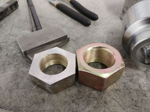
I modified the length of both nuts on the cylinder rod. It would still be ok for this application but making modifications like these adds more time to the production, so hopefully the supplier will be helpful.
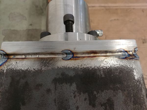
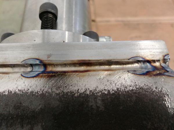
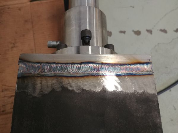
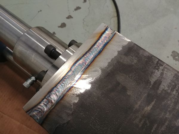
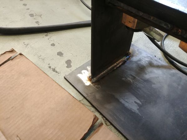
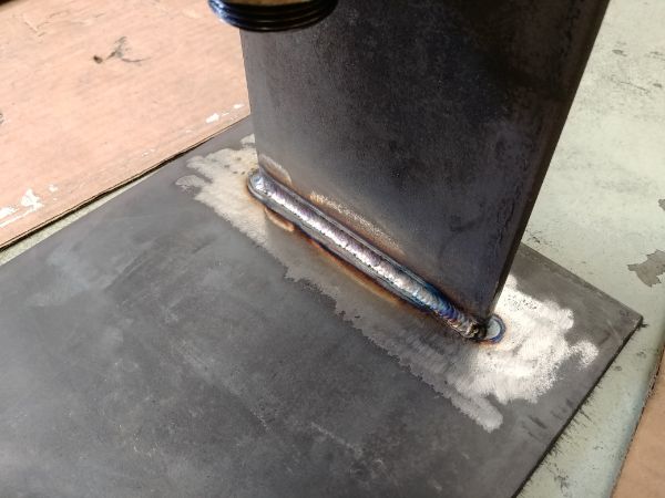
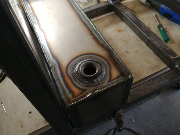
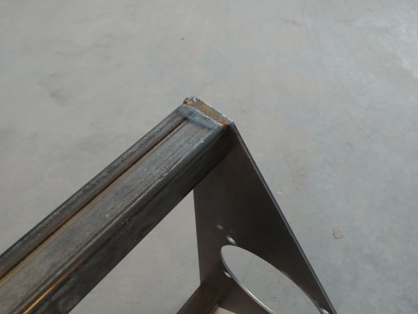
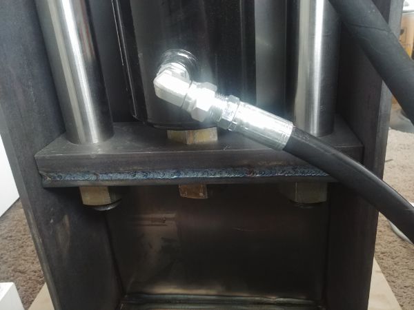
I used a TIG welder to get deep roots all around the weld. The weld does not have to be huge as there are no side loads, although a lot more substantial than that shown below. In the end it covered double the area of the bolts holding the plate down, I believe it is sufficient, but again I will likely increase the thickness more for production, I would also use a MIG welder to lay metal down faster.
I got the sheet cut out for the frame and cleaned up the welding edges. The whole of this press and hydraulic unit will be TIG welded together because that is all I have access to at the moment and what I have at home. It certainly would be a lot cheaper and faster to use a MIG welder in the future. Using the TIG means that all the surfaces have to be free of scale and any kind of impurities. A MIG welder is a lot more forgiving and will often let you weld to dirty metals.
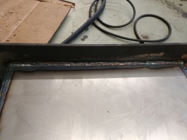
I beveled both edges and cranked up the current to get a deep root weld.
I have to admit that TIG welding looks a lot prettier than MIG, but it is so much slower.
I also placed a few beads of weld on the inside. This whole frame is not a load bearing part at all, but it is likely people would like to use the press as a vise to bend or cut stuff. I thought that by overall making this press sturdy will make it a quality machine.
The welding was getting a little tedious, especially when the 100A rated torch you're using at 150A is getting rather hot. The big problem with TIG is that a lot of heat goes back into the torch and that anything over 100A should be water cooled, that becomes an expensive setup. I have run the MIG at 200A for much longer than the TIG without it even becoming hot.
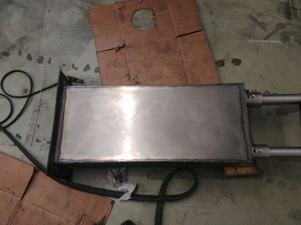
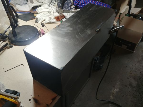
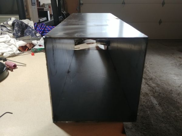
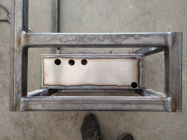
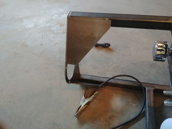
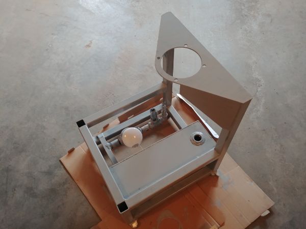
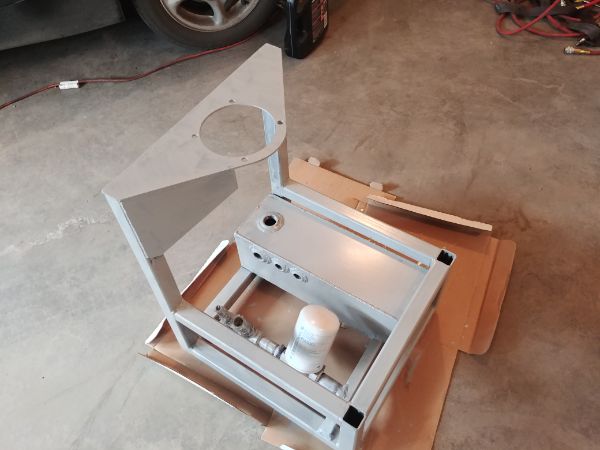
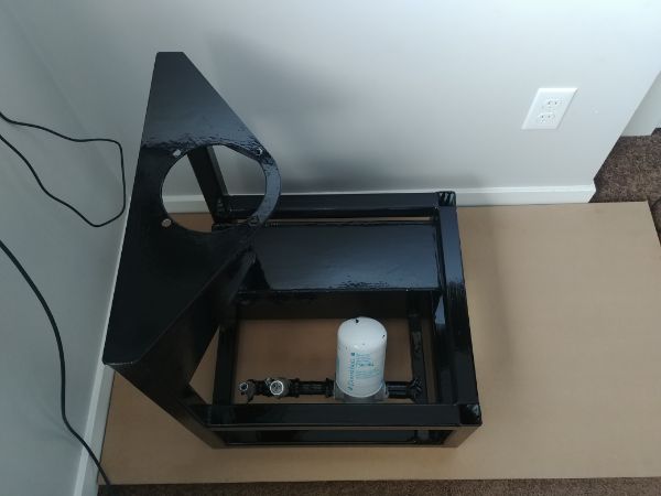
I want to seal off the whole hydraulic system so that no debris can reduce its life. The front cover will be welded in place, the one on the back bolted so that I can gain access.
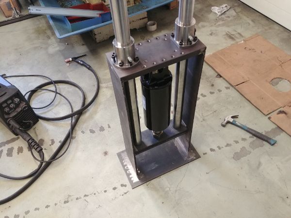
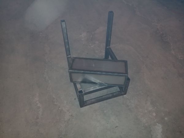
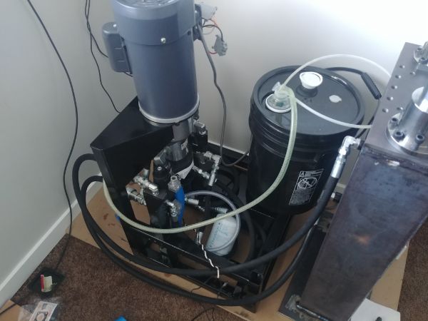
I know how dirty a workshop can get and how all equipment can be exposed to nasties. In this last picture you can see there is a lot of grinding dust on the floor, this contains abrasive and metal particles. The metal is great for destroying electronics and the abrasives for damaging bearings. Using bronze bushes with internal lubrication on my design should minimise the wear, it will however happen to some degree, I have even used grease nipples with sealed caps. I see a lot of design issues with the competitors in that all of the wear surfaces exposed to the elements are also covered in grease. Ultimately the grease becomes a lapping paste contributing to high wear rates. I can replace my parts when they do wear out, they cannot.
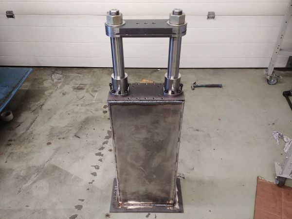
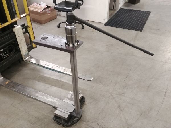
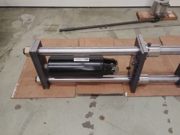
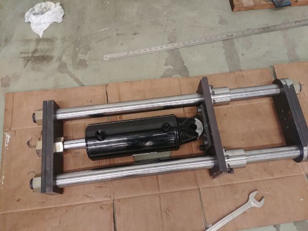
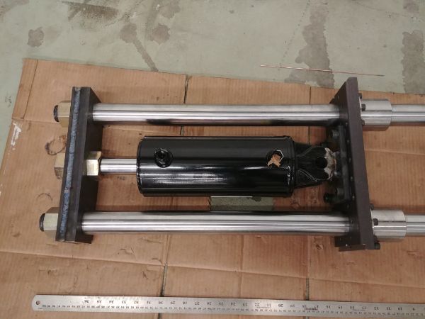
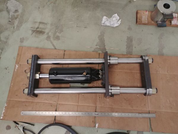
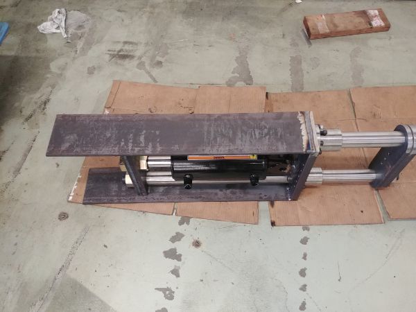
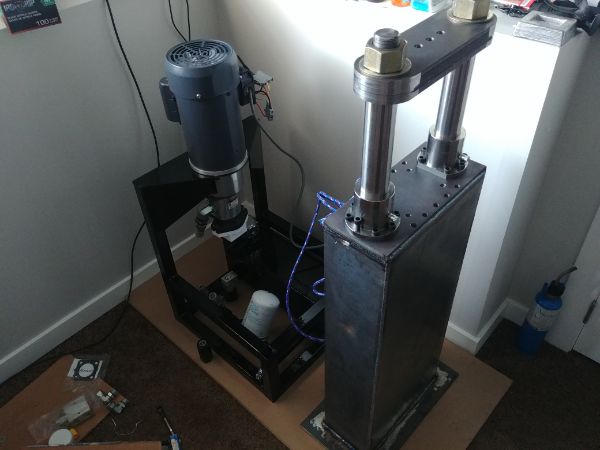
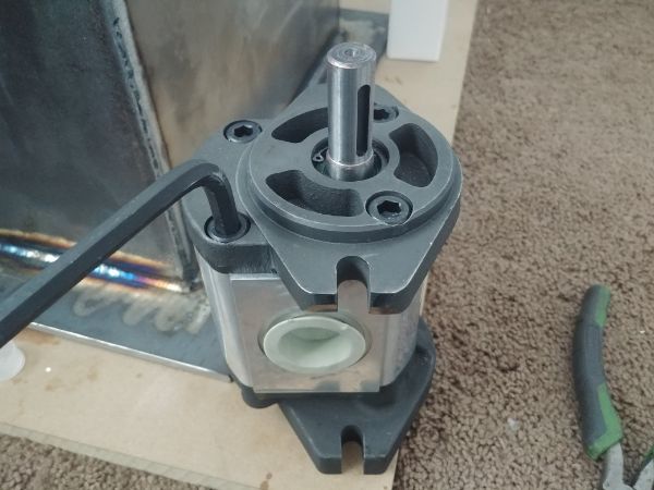
The press itself is mostly complete with exception of the rear cover and a coat of paint.
Building the Hydraulic Unit
The press was pretty easy to design and build in CAD software. The hydraulic unit however took a lot of thought and random doodlings on paper, this was one of those things I would have to build through instinct. I should add that there was some thought however. I spent quite a lot of time searching around for hydraulic pumps and electric motors. I could then make some measurements once I received them and make some updates on the dimensions of the design before going ahead.
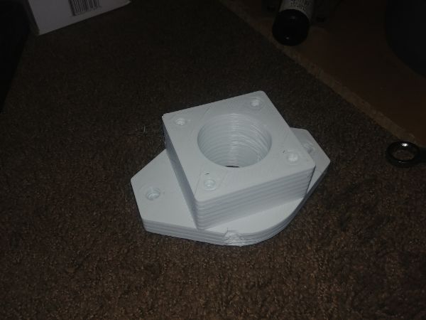
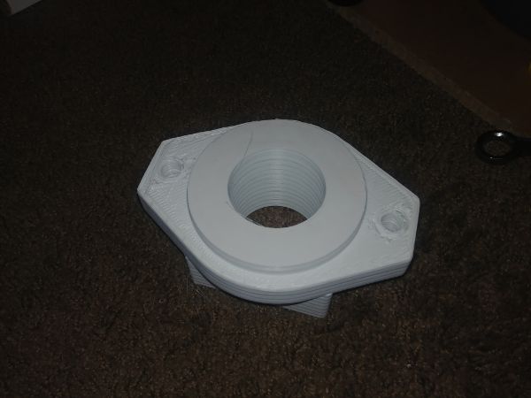
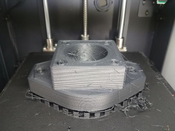
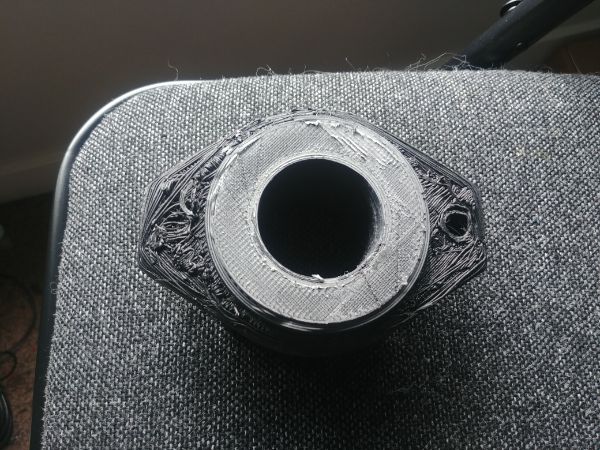
I started out with 3D printing a mount for between the hydraulic pumps to gain an idea of scale. I then thought about actually trying out some 3D printed parts in the prototype, I'm sure they would function fine. Once happy I would then re-machine them in metal for durability. I printed out the first prototype in PLA which fit together ok. I then printed the test part in carbon filled PETG which came out complete garbage. Neither of these prints could be used for testing so I did another in polycarbonate. Although not shown here the print came out great, I will use it in the prototype, heat will not be an issue, but the part may be quite brittle.
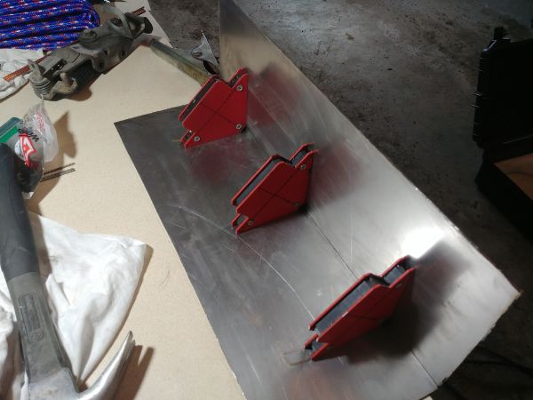
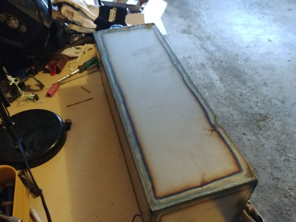
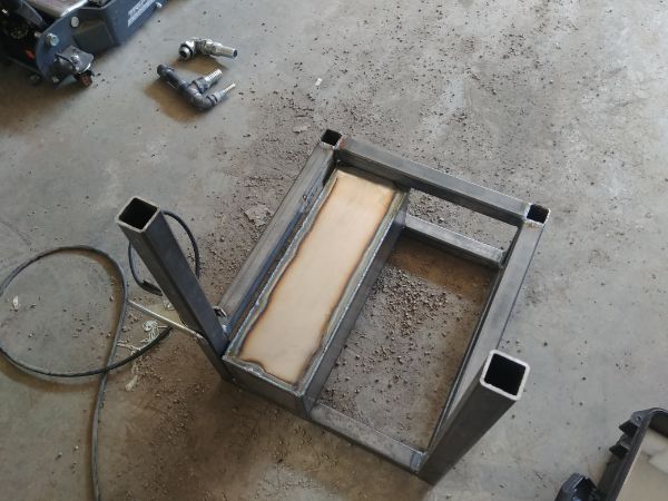
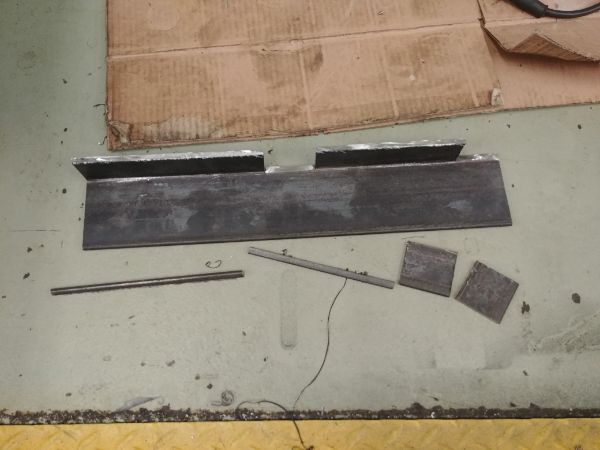
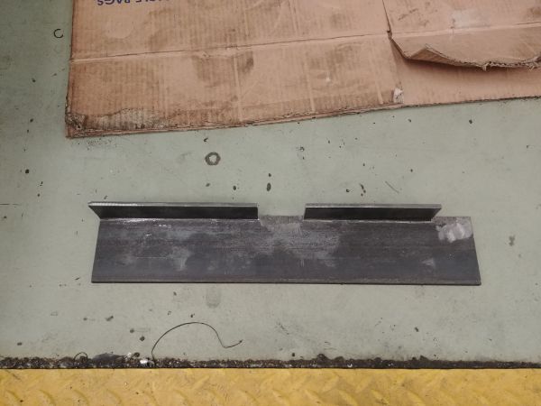
I now knew how the electric motor and pumps would sit, I updated the CAD assembly and started work on the frame. I cut out some sheets that would become the hydraulic oil tank. This is a pretty basic system with a single cylinder, the oil from one side of the cylinder is re-circulated back into the other side. Realistically the amount of oil required in the tank only has to be enough so the pump does not draw air inside of it. The oil tank can also serve a second purpose such as cooling for the oil, the larger it is, the more heat it can dissipate. I designed this tank so that I would have enough oil to fill the cylinder on the first run while also operating the system. I used some magnetic squares to hold the sheets in place and TIG welded some tacks to hold it together.
Once I had all of the panels tack welded in place I could then weld all the seams. I have a very basic scratch start TIG at home which doesn't seem to have enough arc voltage, this means the arc is very short and makes contaminating the electrode very easy.
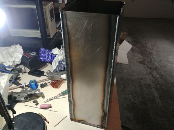
It surprisingly didn't take long to weld this together despite having quite a few issues with the welder. I then made the basic frame out of square tube.
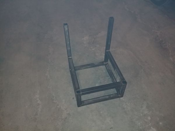
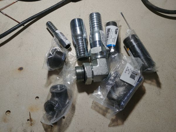
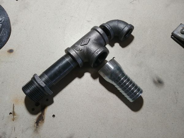
I got some hydraulic fittings for the tank and the high flow pump. I chose to weld a lot of these fittings together since some were technically not compatible and not even intended for hydraulics.
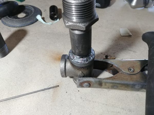
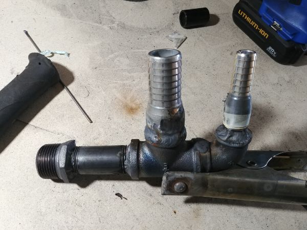
I welded the tank in place and started welding some bungs in place for the hydraulic fittings. I had a lot of issues with contamination and porosity in some of the welds, this is a problem I have only ever had with this welder. I sometimes wonder if my torch is leaking somewhere and actually pulling in air, sort of like a venturi. There is a square piece of box-section that carries oil to the filter. I had issues with every single weld on this piece of tube, just these three welds took me longer than the whole frame itself. I put it down to being a cheap piece of steel since it was like welding a volcano. I kept cutting the weld back and filling it back in, I got there in the end but the weld doesn't look great. I know that if I ever have another welding project that my current welder is being replaced, it is garbage.
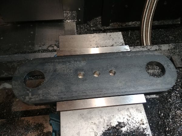
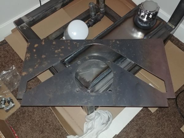
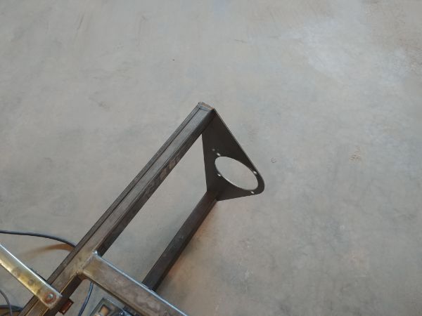
I needed a bracket to mount the motor and I really did not want to make it manually. In the past I would have drilled a series of holes to make the large hole in the middle and then used a hand file to get it round. I instead opted to get it laser cut to save time. If there is a demand for this press then I will get all of the sheets and brackets laser cut, I didn't realise how cheap it was before, and it's a huge saver on time. I asked for the scrap sheet that the bracket was cut from since I had paid for it, I then made two more triangular brackets from it.
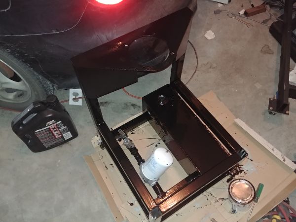
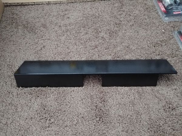
I was happy with the frame and chose to paint it. I figured that I would just bolt or rivet any more remaining brackets if I had to, this is a prototype. I cleaned the metal and painted it with a primer.
I chose to brush paint the whole thing to cut down the mess of over-spray. In the future I would send all the metal to be plastic coated, not only is it more durable but it also saves a lot of time.
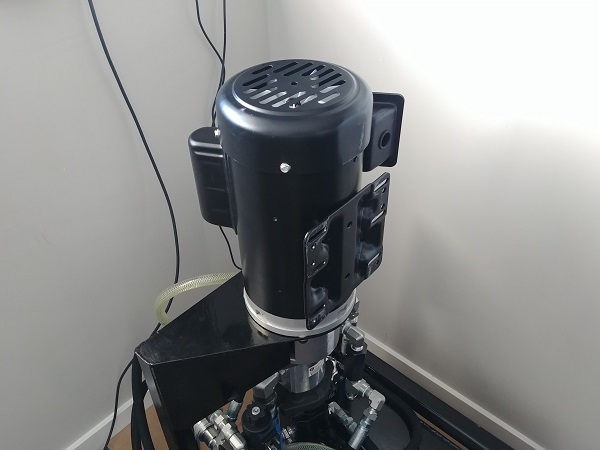
I installed the motor and the pump bracket. This is a 2HP motor rated at 110V at 1730rpm. This motor is a farm rated duty motor meaning it has triple the starting torque and can continuously run at it's peak. The start winding on a motor like this is connected to a switch and disconnected once it reaches a certain speed, otherwise the coil would burn out. A regular motor does not have this switch and the start winding runs all the time, but the starting torque is poor.
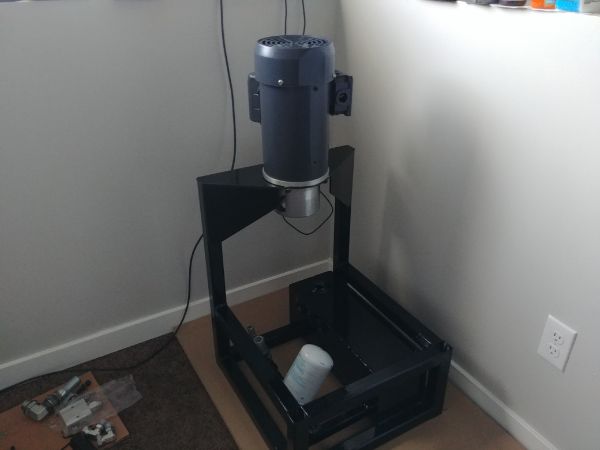
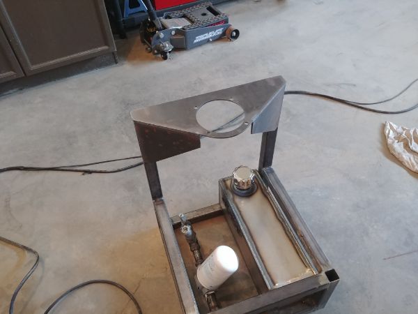
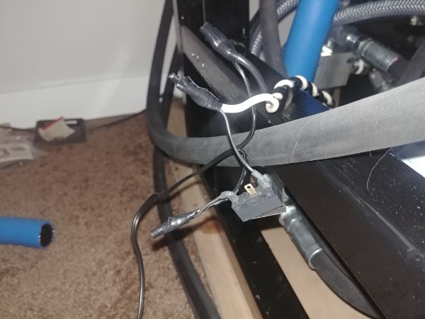
I connected the motor to a plug to check the direction. I was quite surprised to find no terminals of any kind, just wires. North America like the use of twist connectors in everything, but I believe anything exposed to vibration should use a crimp or terminal. I didn't have anything so used DIN rail terminals as a temp solution for testing. I also brought the press home, I had to use an engine hoist to lift it, it would be quite easy with two people.
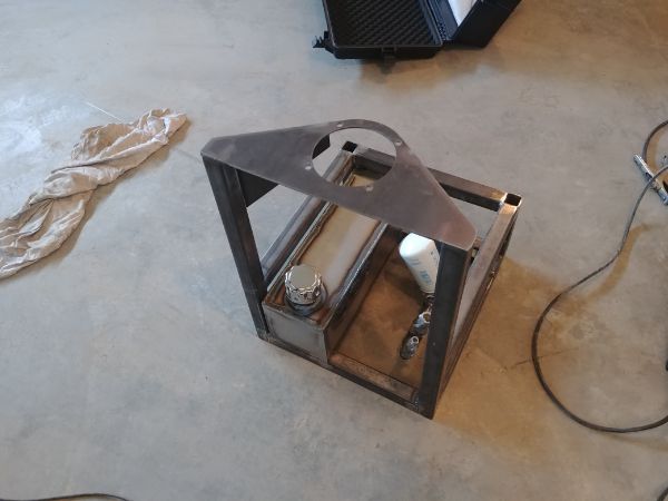
I dove right in seeing how things would fit together or where they would go.
Once I had an idea of where things should go I cut out a piece of steel to make a bracket. I sand blasted and painted it with brake caliper paint, mainly because I can cure it within a few hours.
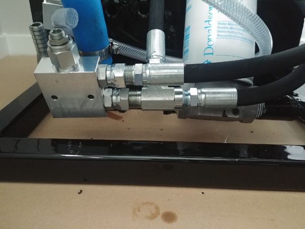
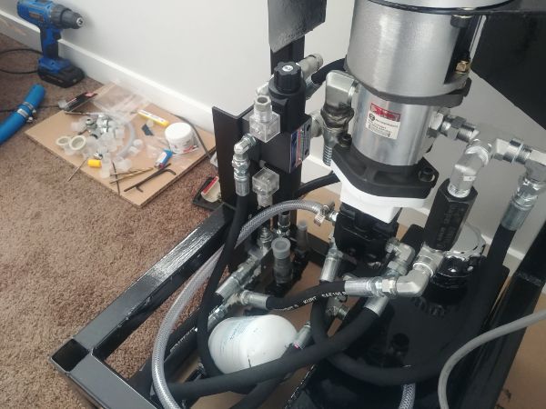
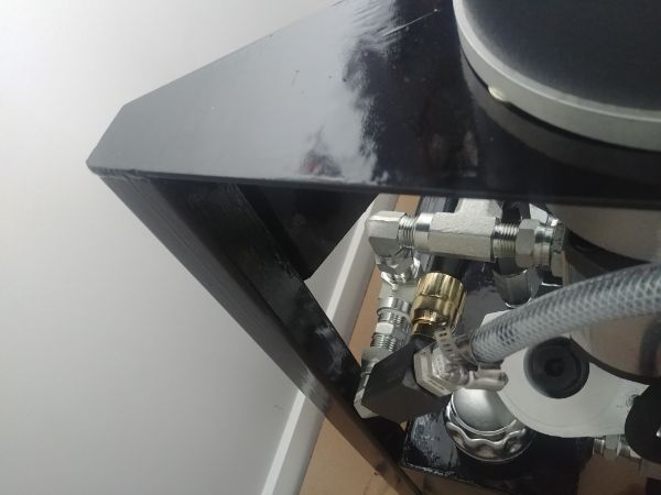
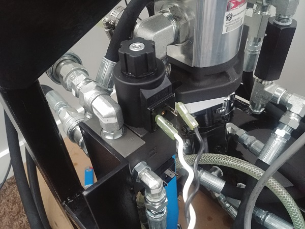
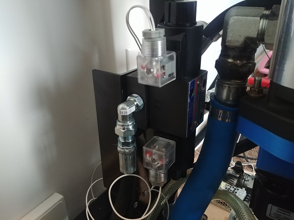
I used some pop rivets to hold the bracket to the frame. I tapped the holes in the pressure relief valve and used bolts to secure it. I also did the same with the directional control valve.
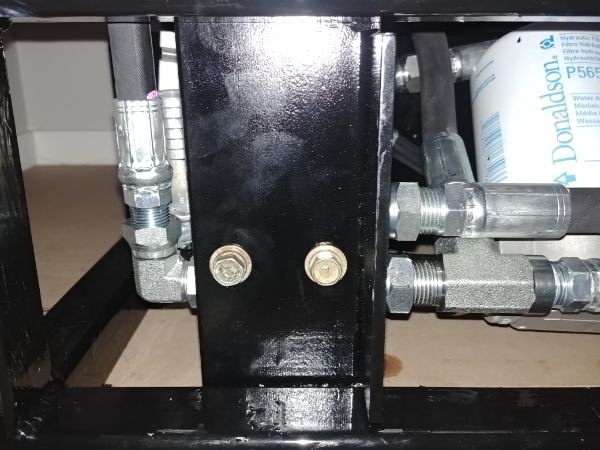
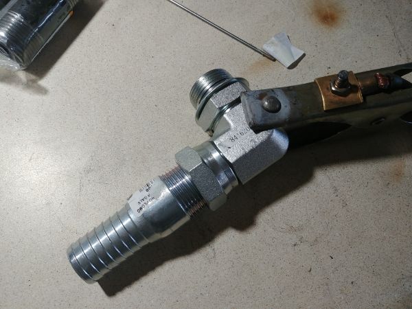
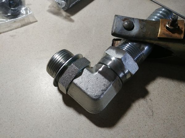
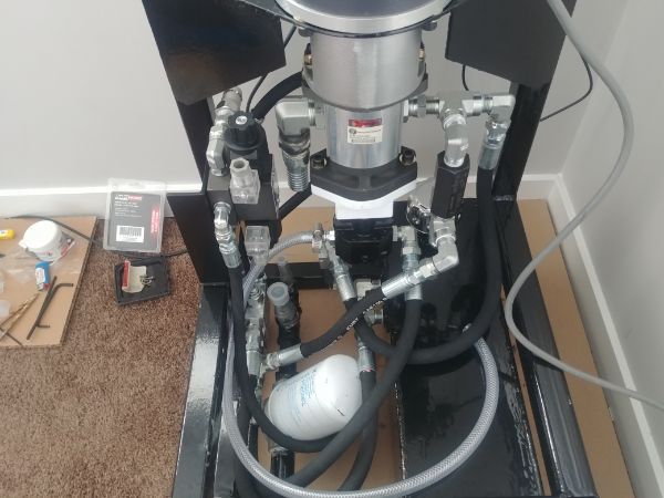
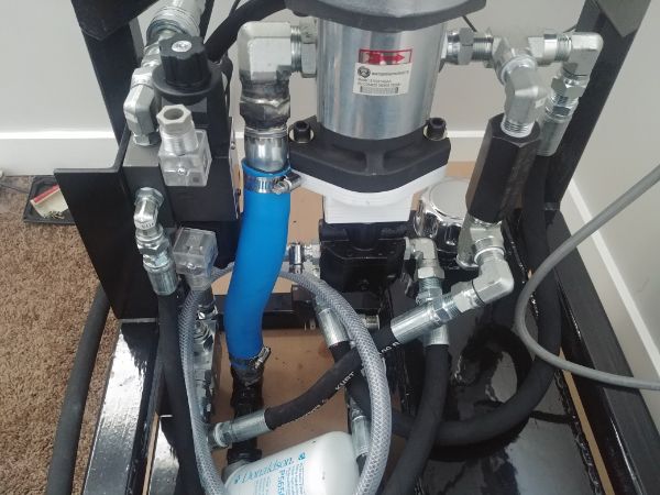
I made sure that all of the tapered fittings used a thread sealant. All of the parts using a swivel type of connector would seal with metal to metal contact on a cone. All of the fittings to pumps or valve bodies use the ORB type fittings with an O-ring and swivel nut. I'm pretty confident that all fittings using sealant and the O-ring will be just fine. I do have concerns with the metal contact sealing, but, this is the hydraulic standard and they would not sell them if they leaked, so I should be ok.
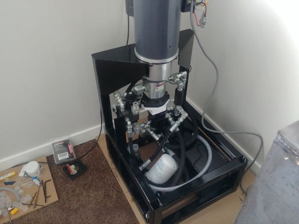
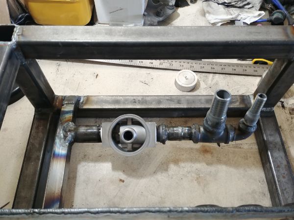
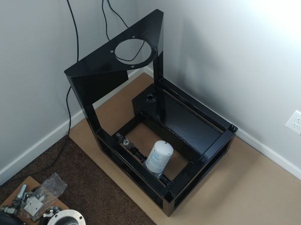
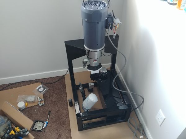
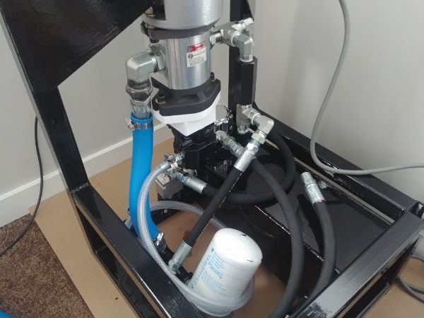
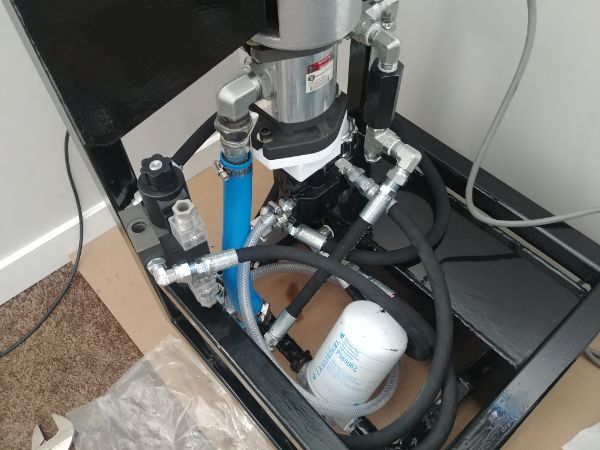
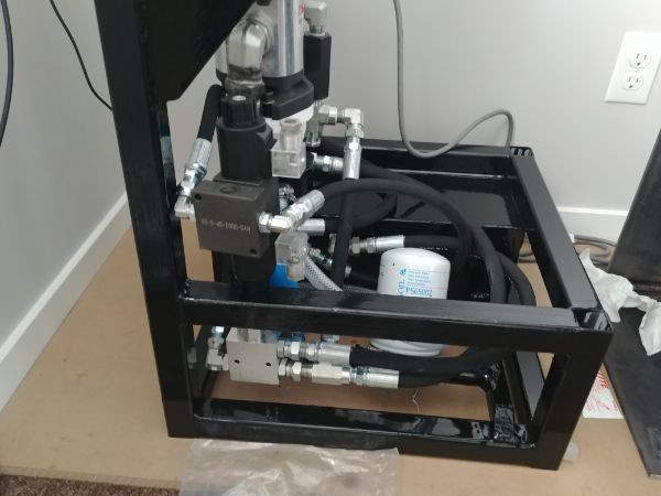
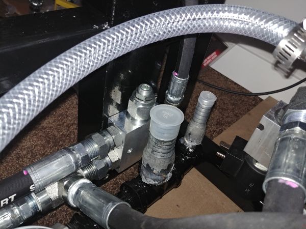
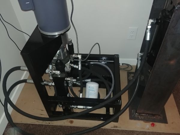
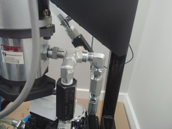
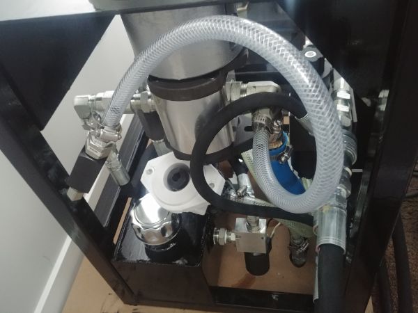
There is quite a lot going on with this hydraulic system, it looks to be complicated but is actually very simple in operation. The only thing left to complete in these pictures is the supply hoses from the oil filter to the pumps. The high flow pump is coupled to the electric motor via a spider type coupling. The high pressure pump has not been connected yet because I need to make something to adapt the shafts.
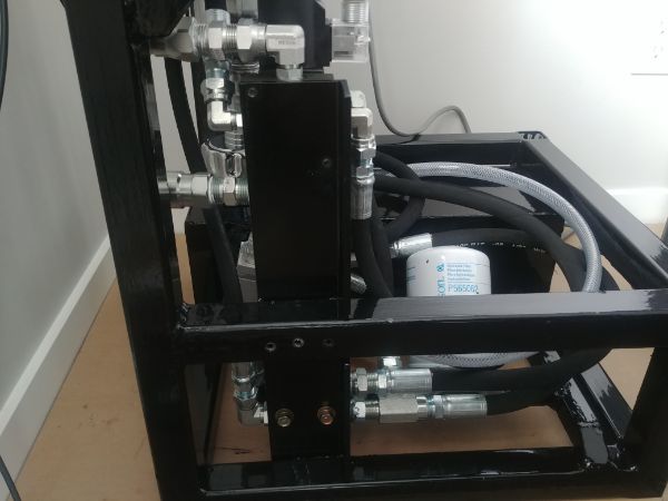
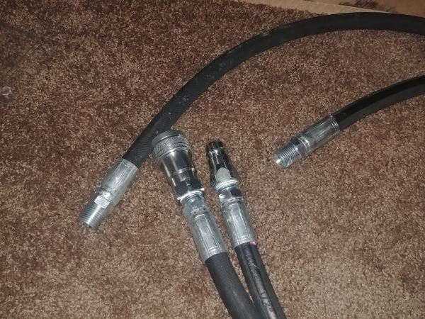
The hoses connecting the directional valve to the hydraulic cylinder have a quick coupling between them. The idea is that the hydraulic unit can be placed at a distance from the press itself. Also the press can be easily removed from the hydraulic unit to ease in transportation without requiring any special tooling or the system to be bled. The only thing I'm not happy about is how the hoses protrude out of the back of the unit, this was not intended initially, some modifications will be made after testing. I would like to seal the whole hydraulic unit off with removable panels to keep dirt out.
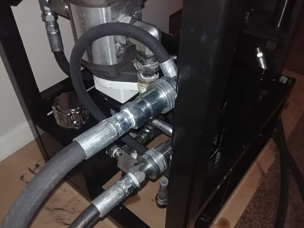
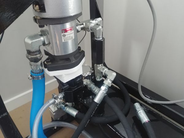
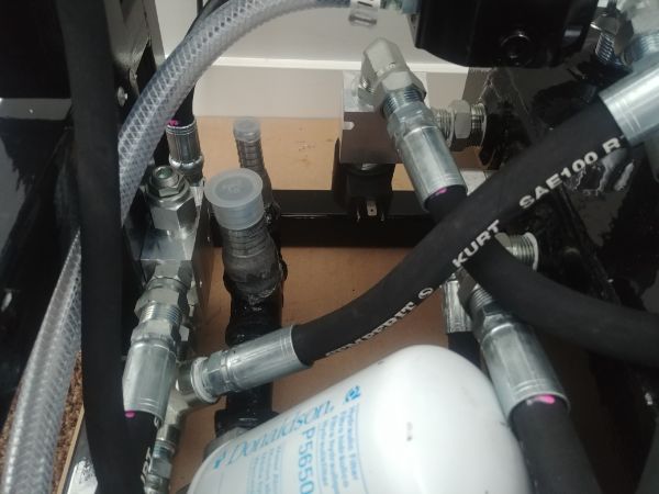
The hoses were connected to the cylinder. The hoses were also connected from the oil filter to the pumps. The whole of the hydraulic system is now complete, all connections are sealed and there should be nowhere for oil to escape. I should also add there is a blanking cap in place of where the electronic pressure transducer will sit, I have not bought the sensor yet.
High Flow Pump Test
The reason to test the high flowing pump first is so that it can run all dirt throughout the system into the filter. I also want to ensure that the electronic bypass valve will allow the pump to vent without there being much load on the pump itself. To check the load I will connect a power meter to the motor supply. The press is still very tight and I doubt the high flowing pump will be able to move the hydraulic cylinder at all. I will admit that I am a little concerned at that the high flowing pump is a little too big as I worked it out to be 1.9HP at 200psi. The fast movement should only be capable of around 1.6 tonnes, that would be fine once bedded in, but not at the moment. If the bushes do not bed as I expect then I would dismantle the pump and machine down the pump gears and housing.
I filled the tank with some oil, enough to fill the pump but not enough for the cylinder, one step at a time. I connected a 12V power supply with a normally closed switch in between to the pump bypass valve. The idea is that oil will circulate through the pump and straight back into the tank. If I press the switch which will close the valve then the fluid will pass through a check valve to the cylinder directional valve and then back into to tank.
The first test was a bit of a failure since I kept tripping the circuit breaker. I knew that my pump was a little on the large size and that it would supply around 11GPM whereas the valves are only rated to 10GPM. I chose to remove the pump and take it apart. I was thinking of grinding away a portion of the gears so they would become less effective. I had a rethink and realised I could put another bypass on the pump.
I welded another hose barb on the pump inlet and then added some extra plumbing on the outlet.
This needle valve would allow me to adjust the amount of oil that would re-circulate directly back through the pump, with this I could reduce the load on the electric motor.
The electric motor stopped stalling when I disengaged the return valve. The hydraulic fluid actually spun up the high pressure pump like a motor, a bit of a problem because that would circulate fluid back into the tank. I applied power to the directional control valves and it moved the press up and down. If I closed off the pump bypass further it would increase the speed of the hydraulic motor and the speed at which the press moved.
However, the breaker would trip before I could close the valve all of the way. I knew I was cutting the power of the motor close to the size of the hydraulic pumps. I did some thinking and chose to upgrade to a 3HP 230V motor, not an expense I really wanted to pay. Again if these were to go into some kind of a production run then I would source smaller pumps to keep with the 110V outlet, so I guess mine could be seen as an upgraded option. I run the pump again and could even run it with the bypass valve closed. The press moved up and down faster but as a consequence so did the high pressure pump, it will be interesting to see how fast it moves when this is not bypassing fluid.
High Pressure Pump Test
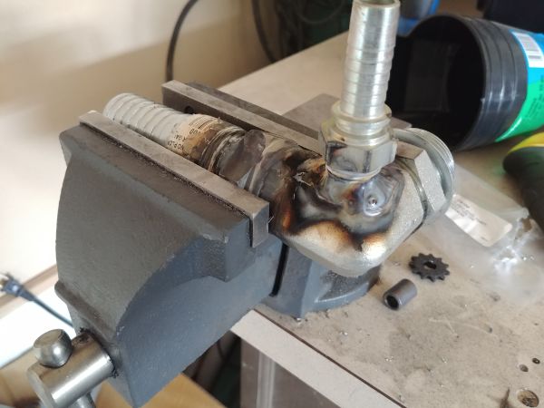
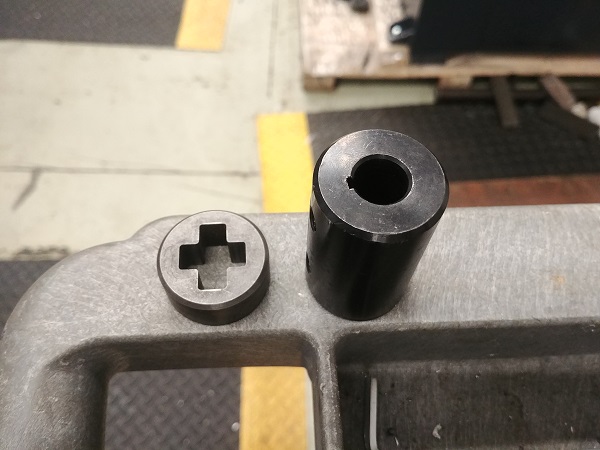
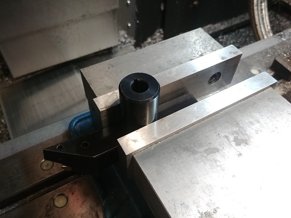
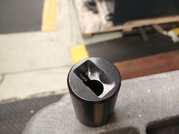
The high pressure pump was acting like a motor since the shaft was not connected, it was also bypassing fluid back into the tank. I knew that the next test would be the high pressure operation. The very first thing would be to connect the output shaft from the low pressure pump to the shaft of the high pressure pump, ideally with a flex coupling in between. The coupling provided is a hardened piece of steel with perpendicular slots, the output shaft fits into one of these. The shaft for the high pressure pump is a general keyed half inch round rod. I decided that I would mill a slot into a coupler so it would engage with the rectangular shaft.
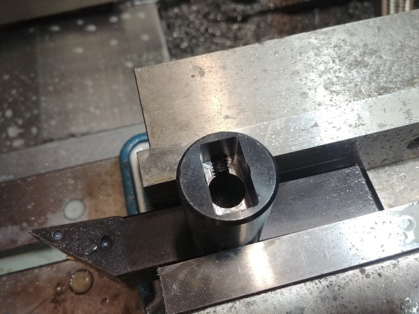
I made the slot oversize so that I could press a soft insert inside of it. I 3D printed the part and installed it, unfortunately I forget to take a picture. The plastic chosen was PETG which should prevent any kinds of shock vibrations, the steel certainly would not have done so.
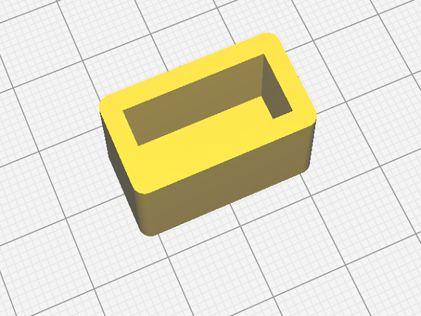
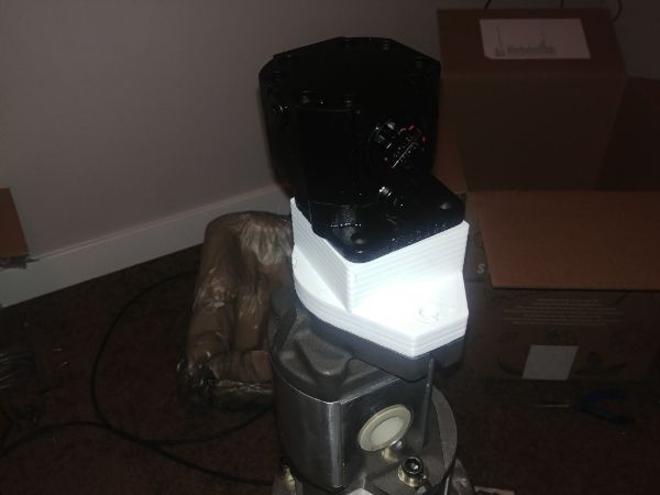
Earlier I had made some attempts at 3D printing a housing that attaches both pumps together, these were a bit of a failure. I chose to re-print it out of polycarbonate which will not only handle high temperatures but should also be plenty strong enough. The whole thing fit together perfectly and I managed to get the high pressure pump bolts very tight into the plastic. The final revision of the press will have something a lot more substantial than plastic, this does however prove 3D printed parts can be used.
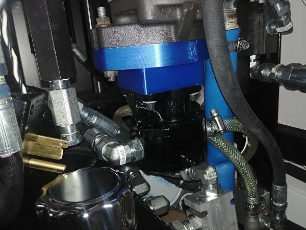
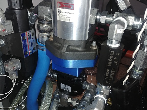
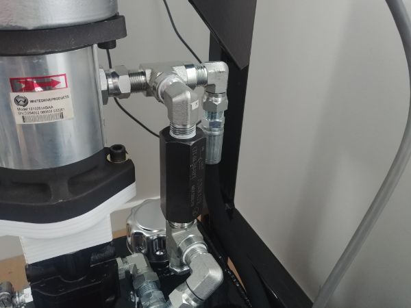
I also noticed that the port for the rod side of the cylinder looked to be quite restricted. Although not shown clearly in the second picture I chose to drill it out to twice the diameter. I'm hoping this would help to increase flow and the speed of the ram. I made sure to drill slowly so that any swarf that would end up inside the cylinder would be small, the swarf would be able to work its way into the oil filter.
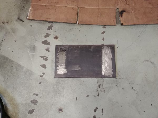
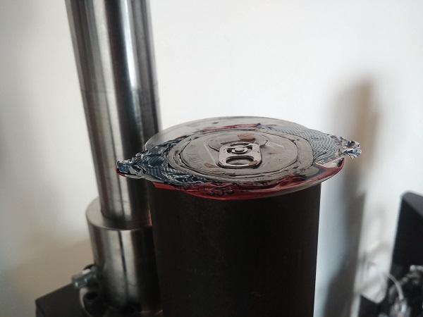
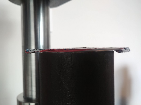
I decided to test the cylinder operating on the fast movement, at first it stalled the motor. I had to open the manual bypass valve by around 1GPM to stop stalling, this was also the estimated flow of the high pressure pump. I then allowed the low pressure pump to bypass with the electronic valve back into the oil tank. The high pressure pump then drove the cylinder up and down at a much slower pace. I chose to crush a can at full pressure, I believe being 2100psi (I will add a pressure gauge at a later date). I did notice that at full pressure the top plate actually bowed slightly, I guess it was to be expected since made from two pieces. At this pressure it would be 37,000lbs, at 2500psi (cylinder rated) it would be 44,000 lbs and at 3000psi (should be ok at) would be 53,000 lbs (24 tonne).
The Electronics
This is what makes this press very different from the others. The electronic system will consist of;
High flow bypass Valve
Cylinder Directional Control Valve
Low Pressure - Pressure Transducer
Motor Contactor
Foot Pedal
Mode Selection Switch
Press Limit Switch Top
Press Limit Switch Bottom
Speed Control Potentiometer Low Speed
Speed Control Potentiometer High Speed
As you can see there is quite a bit to this design or this is what it would have been before I had a re-think. I realised how expensive the pressure transducer would be and what its actual task was. In basics it measured the pressure at the point where the motor would stall, it could then switch from fast to slow operation. I decided that measuring the current through the motor would not only be cheaper, but would allow me to gain as much speed out of the press before the motor stalled. The stall current would remain the same throughout the motors life whereas the pressure required would reduce over time as parts wear and loosen up.
I want to seal off the whole unit to ensure a long working life, by doing this it would make fitting limit switches difficult. I could have used adjustable ones on the outside or fixed ones on the inside. The issue with both is that they require additional wiring to the control unit, this adds more parts susceptible to damage and more parts required if locating the units separately. I also figured it would be pointless to have a low speed control knob as this would be controlled with the foot pedal. I did decide to keep the high speed control knob as this will control the pressure bypass.
I realised that by adding the manual bypass that I could stop the motor from stalling on the high speed setting. I would hope that as the unit wears I could decrease this flow and increase the speed. The only issue with having a bypass linked directly between the inlet and outlet of a pump is that it can cause cavitation. Cavitation is air in the system which foams up the oil, makes operation noisy and generally isn't good on wearing parts. I figured that now I have the higher power pump that it would not stall on starting. I could then electronically modulate how far the electronic bypass opens and therefore how fast the cylinder moves. If I completely eliminate the manual bypass then I should be able to stop cavitation completely.
Lastly I hope to simplify the whole of the system once I have got it working. I am in contact with a supplier that can not only get me smaller pumps, they can be tandem-ed together properly and even have integrated electronic bypass valves. So now I have updated the way the electronics will work I now have to consider;
High Flow Bypass Valve - PWM - Variable Flow Rates
Cylinder Directional Control Valve - Normal Operation
Motor Relay - Heavy Duty Relay Rated for Motors
Motor Current Sensing - Measure the Load of the Motor
Mode Selection Switch - Two Modes of Operation
Foot Pedal - Controls Speed and Direction of Cylinder
Speed Control - Controls the Fast Movement Speed / Bypass
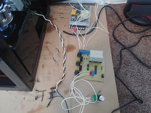
I think I'm pretty adept at making control type circuits and seeing them through to boards. I spent a few hours designing the board before I engraved it on a PCB mill. The really cool thing with milling a board is that I could make the custom elongated slots for the relay. I could also cut custom sized holes for securing the board and cut it to any shape I like. I originally thought that I would like to get these boards professionally etched, but now I'm not so sure, it came out really good.
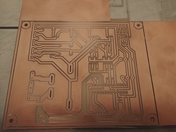
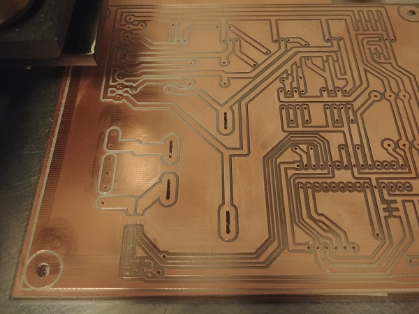
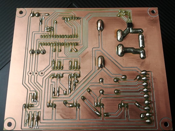
I knew I could have made the odd mistake since it didn't take all that long to design. There was one trace I had to cut and two jumpers I had to add, but ultimately nothing major. I updated the PCB design and even made some more improvements, maybe I'll get a quote on a board. The most important thing was that the relay fit, one rated to switch up to 3HP motors. The rest of the board is some very simple electronics, I do believe it will be a reliable, robust design. The only thing I forgot to order was a single terminal block since I recycled most of these components from a past project.
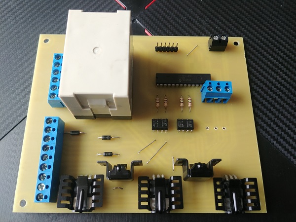
I wrote a simple program for what I had so far, I also prefer to work in smaller stages, it makes solving errors easier. I first started by connecting the directional valves to the board and the board to the power supply. I connected a potentiometer that will be used in the foot pedal. The middle position including a few degrees each way will keep the cylinder stationary. Moving it one way will raise the cylinder and the other way will lower it. So far it is working perfectly.
The next step is to control the fast movement of the cylinder with also the addition of another potentiometer, I however need to pick up a terminal block. Once I am happy with this part, although I'm assuming you can modulate the opening distance of a hydraulic valve, I will move onto the motor control. I have soldered a chip in place which will read the current flowing through the relay, with that I should be able to measure at which current the motor begins to stall. Although before I do that I want to clean the board of all flux and paint it with conformal coating, this is 220V I'm playing with after all.
Once the electronics is all working perfectly I will need to find somewhere to put it. I will also need to add a socket for the foot pedal which will also include the mode control switch and the high speed control potentiometer, I think keeping them all together complicates things less. I will first build a prototype of the foot pedal from plastic and then remake it in metal. Lastly will be a shroud for the whole unit to cover everything. I think I may have to add some cooling fans with filters to prevent the inside from getting too hot.
After all of that I will then consider the next steps. That will be sourcing a better choice of pumps for the 2HP motor, I will likely make a completely separate hydraulic control unit. As for the press I will look into upgrading the top and bottom plate to stop them flexing. It will either require a better grade of steel or a thicker piece. Otherwise this page is getting pretty full, follow the link to the second page.
Hello, if you have enjoyed reading this project, have taken an interest in another or want me to progress one further then please consider donating or even sponsoring a small amount every month, for more information on why you may like to help me out then follow the sponsor link to the left. Otherwise you can donate any amount with the link below, thank you!