Precision Hydraulic Forging Press - Page 2
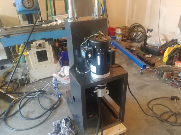
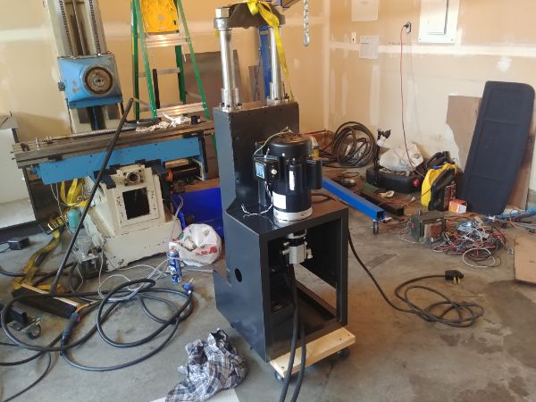
This is the second page into building my precision hydraulic forging press. So far I have built the press itself and the hydraulic unit. I have tested the basic function of the system and now I'm ready to complete the electronic control module. Since the majority of this project is in the prototype stage I won't quite be considering the absolute final product.
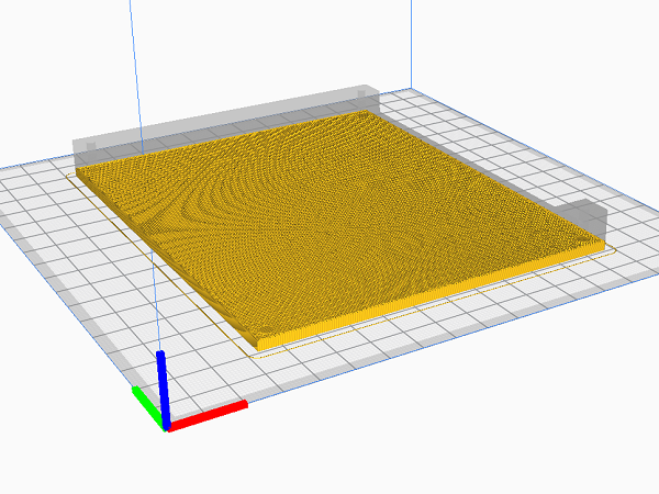
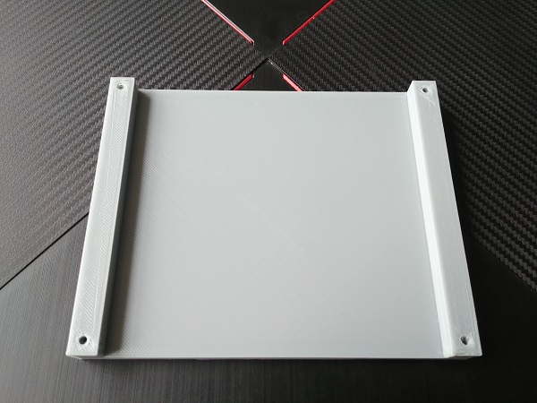
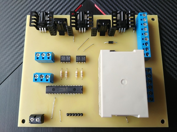
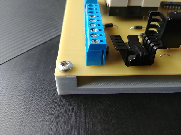
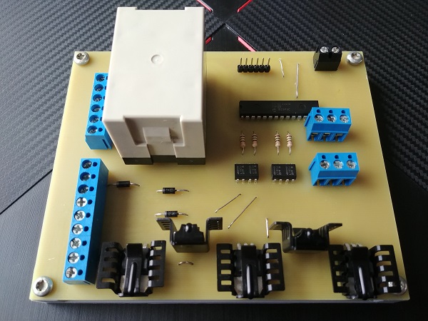
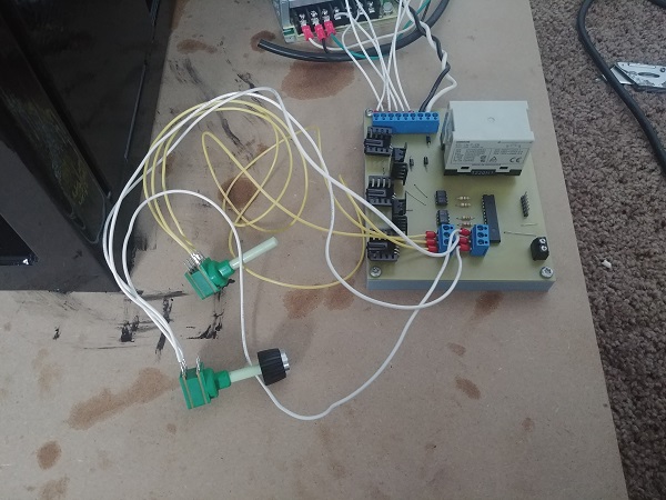
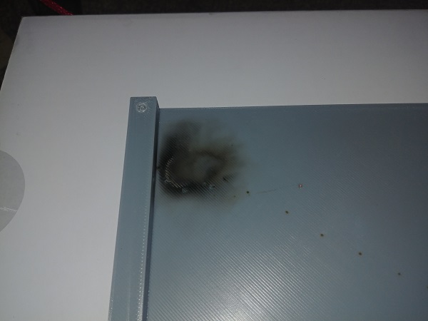
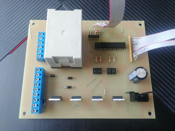
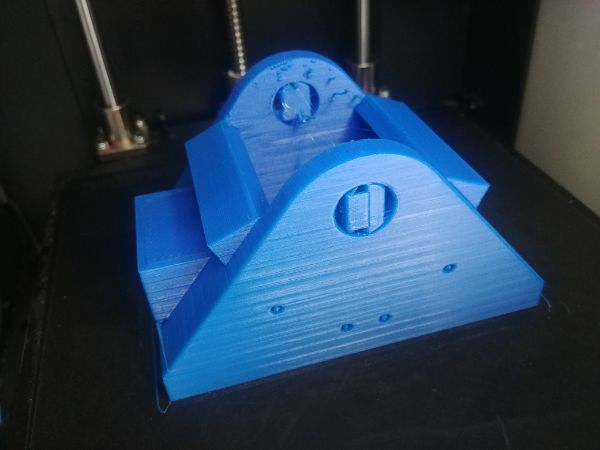
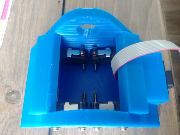
So the circuit board has mostly been populated and I'm using it to control the electronic valves. Since it is just a bare board and a couple of the terminals are exposed to main voltages, 220V in this case, I must protect it from shorts. I designed and 3D printed a base for the board so that it would sit nicely and prevent any mistaken shorts. This board is for the function of prototyping and will not make its way into the final product.
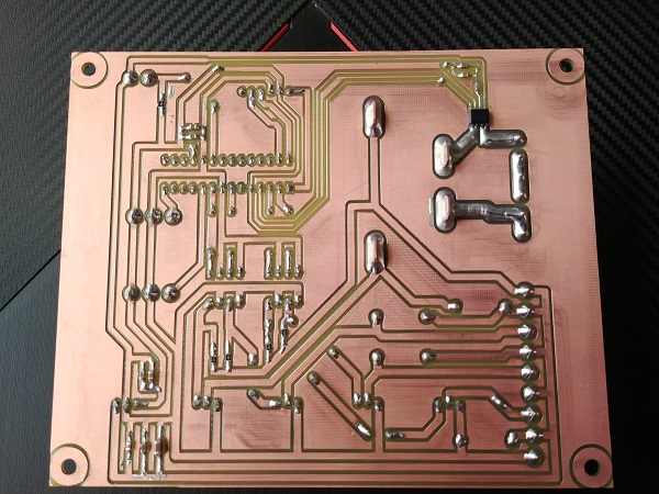
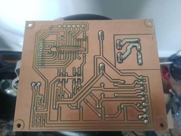
I picked up some more terminals to finish off the board and gave it a thorough clean to remove flux residue. I applied a conformal coating to the underneath of the board, most importantly around the relay to prevent any kind of arcs. In theory I should be fine leaving the board the way it was, but this extra precaution is in the event of high humidity.
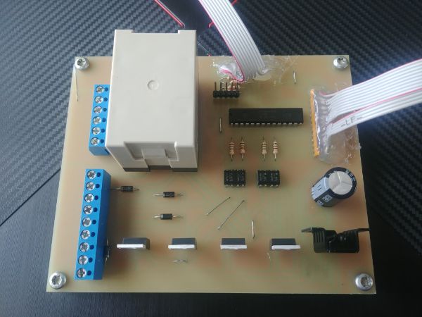
The board screwed down to the base, now there should be little risk of shorts or mistaken electrocution.
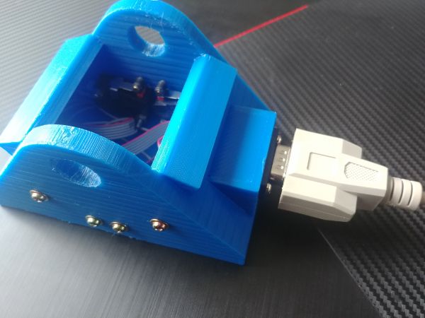
I had already connected a potentiometer to control the direction of the cylinder. It was now time to connect the second potentiometer to control the speed of the electronic bypass valve. I added some extra code to the program that would pulse width modulate the valve and be controlled via the second potentiometer. I will add that both the bypass potentiometer and that for the direction will both control the speed. The bypass pot will say for example set the duty at 80%, the direction pot will then control the duty from this 80%. With this method it gives a much more precise control of speed. If I were to base the directional duty at 100% and then allow the bypass to cap it at 80% then there would be no need for the bypass at all, also it may be difficult to tune the slower speeds (if all that makes sense).
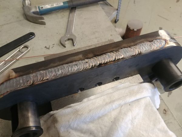
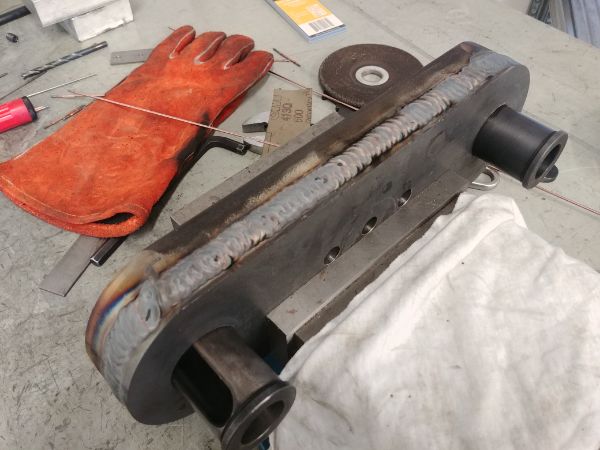
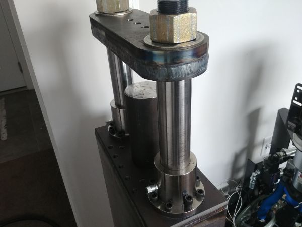
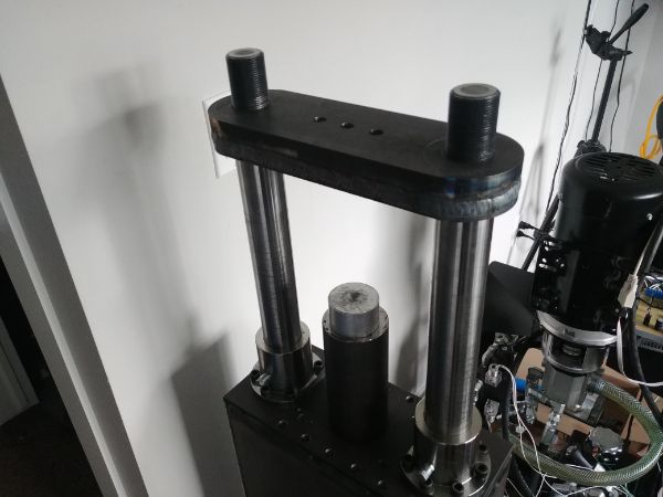
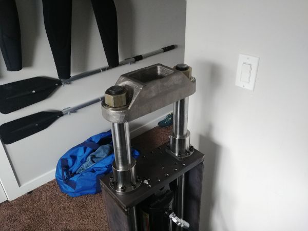
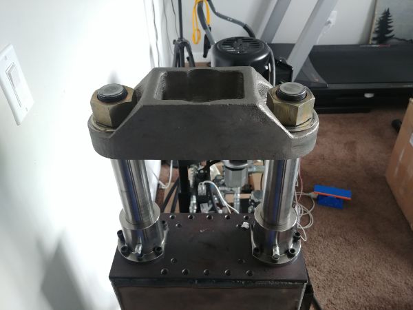
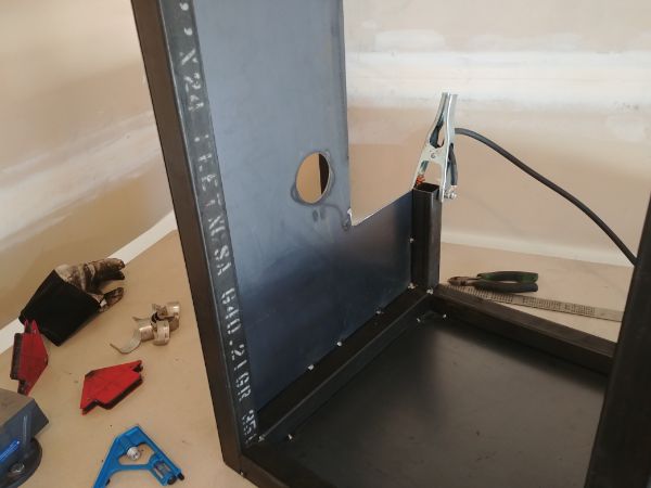
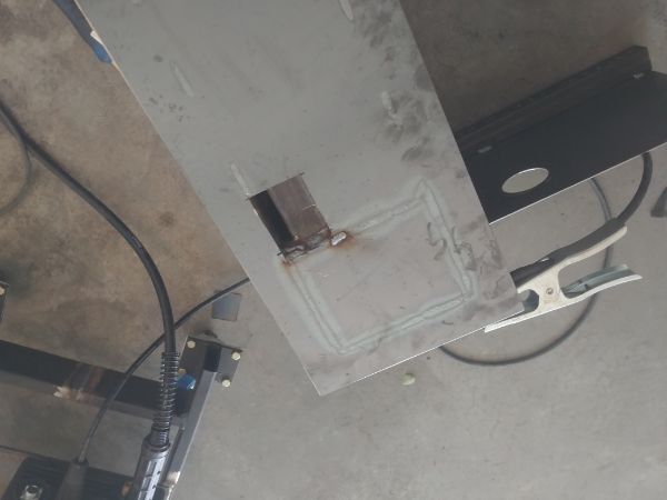
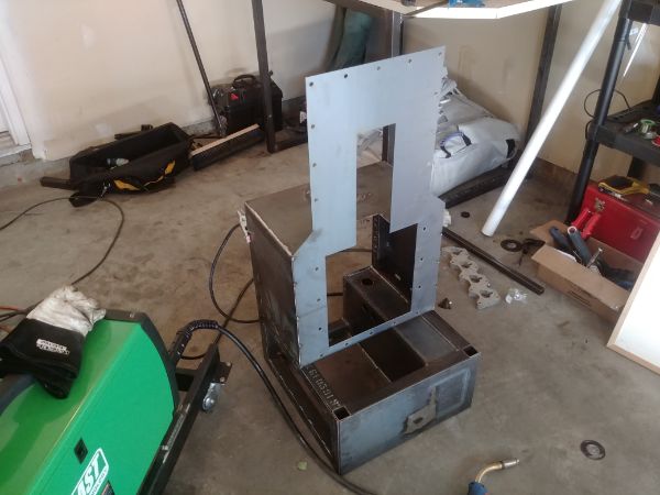
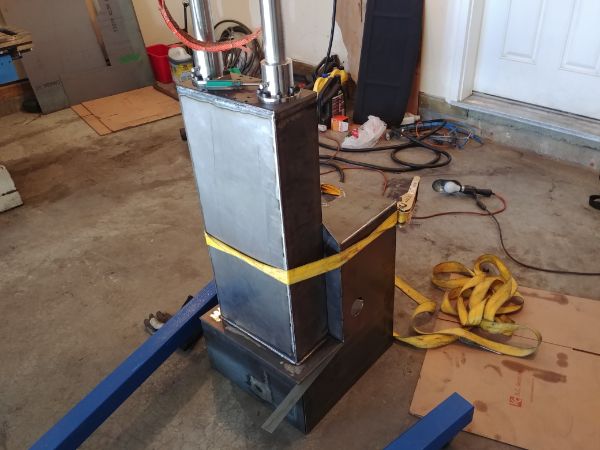
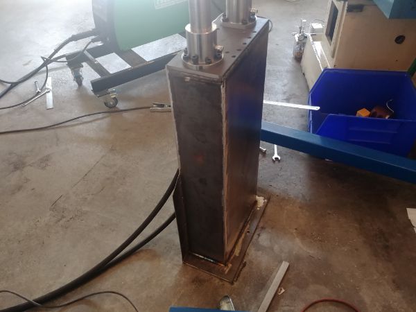
Before testing the press any further I chose to make some modifications to the press itself. I removed the top plate because I noticed it flexing, likely because it is made from two pieces. I ground into the separation to get a deeper root weld. If I do decide to make any more of these presses then I will go with 1018 steel instead of plain old fabrication steel.
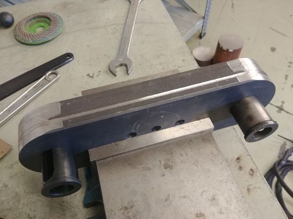
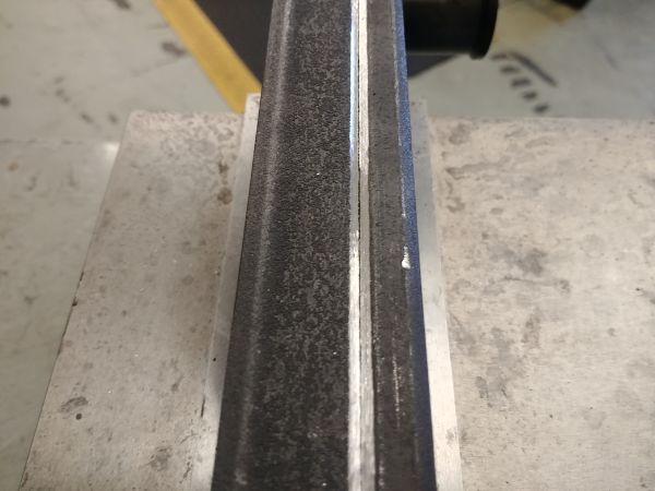
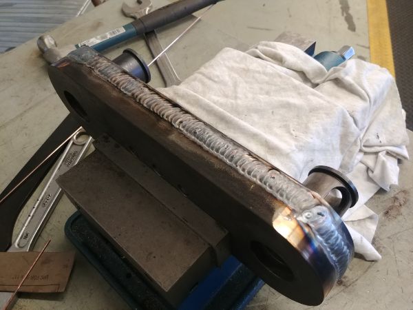
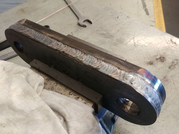
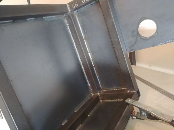
I used some steel bushings to align both of the plates and placed them in a vise. I welded a root pass without filler around the full circumference of the plate, I then added some filler rod on the second pass. I did one last pass to blend the weld a little better, its not the best welding but will suffice.
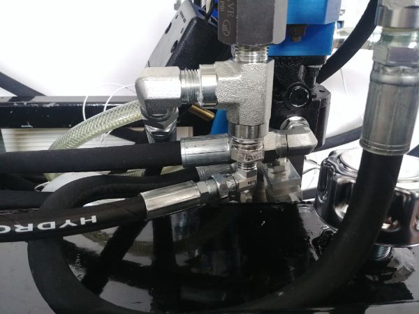
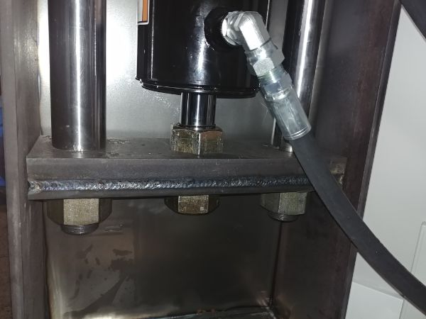
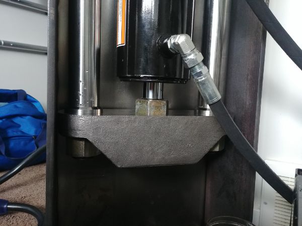
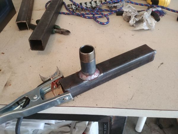
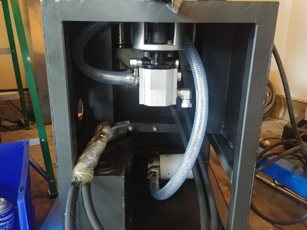
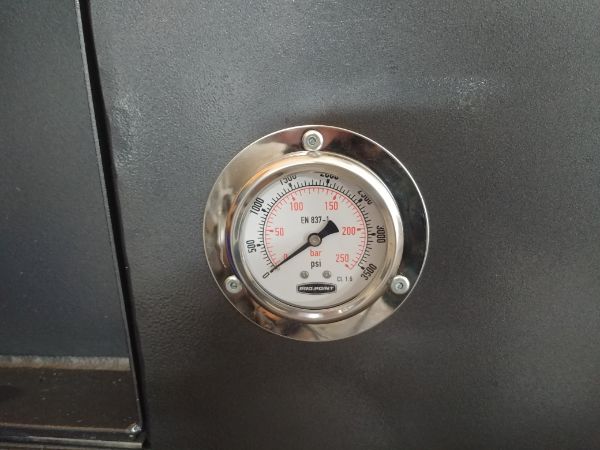
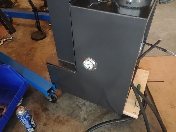
On a separate note I wanted to increase the working pressure and get the most out of the press. I had installed a bung for a pressure sensor but because of a design change I did not need it. Instead I connected a pressure gauge to the port, this will later be at the front of the unit.
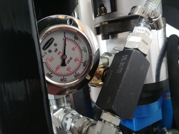
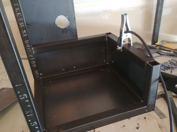
I installed the top plate and tweaked the pressure relief valve. It was originally set at 2100 psi, I turned it up to 2900psi. The hydraulic cylinder is the only component not rated at 3000psi, however it has a shock rating of 6000psi, I figure it will be ok. I noticed the plate flexed a lot less even at these higher pressures, this is just over 23 tonne. The bottom plate was already welded so it should be ok, I will however upgrade it to a better steel.
I noticed a big problem with pump cavitation due to the manual bypass valve. I shut it completely off for the above testing but could only run the slower speeds as the motor would stall otherwise. The only reason cavitation happens in this design is because there is no check valve on the inlet of the pump and the oil drains back into the tank. In future designs I will incorporate a low pressure check valve, I will also remove the manual bypass.
The next test is with the modulated electronic bypass and the manual bypass totally closed. I played around with the program and potentiometers before powering up the pumps. I did notice that the electronic bypass sounded to be either on or off and there was quite a large hysteresis gap. I pretty much knew what the result was going to be but went ahead and turned on the motor. After spending a bit of time adjusting the modulation I found the valve was either on or off.
The result was quite expected since a solenoid pulls harder the closer it is to the end of its travel. An electronic proportional control valve is what I would require, I however knew how expensive these were so didn't even entertain the thought of purchasing one. A proportional control valve has a constant flow rate regardless of the pressure. The solenoid is built slightly different in that it has no ferromagnetic stopper at the back, instead a spring. The more current that passes through the coil the further it pushes the spring back opening an orifice and increasing flow. I could modify the existing solenoid on my valve but that would require some intricate machining, not quite worth it.
Where does this leave the project, well there is the option of a manual adjustment or not even controlling the speed at all. I would instead make the foot pedal to be two speed, fast and slow. The control circuit would still work the same in regards to detecting high currents and automatically switching over to the slow speed. The extra potentiometer would instead be used for a timer. The press has two modes of operation. The first is that the pedal controls both up and down. The second mode is that the pedal moves the press down and once released a timer raises the press, the potentiometer determines this time and therefore how high it travels upwards.
I will revert back to partially opening the manual bypass so the motor does not stall. I will then work on the current sensing of the motor. I can get the press functioning how it should and complete the electronics. Future hydraulic units will have smaller pumps and no need for the bypass valve. Once I am happy with the hydraulic unit functioning properly I will then address the press itself. I did notice some flexing in the top and bottom plates, this may lead to stress fatigue in the future. I can try upgrading to 1018 steel, pricing out a custom casting or make a supporting structure.
Failure ! I decided to do some more testing despite knowing I could run into issues. I re-wrote the program so that the control potentiometer would determine the direction of the cylinder, it also switched on the motor. I programmed some hysteresis into the potentiometer so that no relays would click on and off when the threshold was hit. I connected all of the wiring to the board so that it could measure the motors current and switch from fast to slow. It all seemed to work apart from the current threshold would always be hit before the cylinder bottomed out.
I kept playing around and found that even at the current sensing chips limit and more than 25% over the motors rated current, it kept tripping the program. I made the program simple so that it would measure the peak current, just a single detection over peak would trip the program. I could have re-written it to make a couple of measurements and made an average, this I felt was over-kill at this stage. At a later date I would also program it to measure peak currents on starting, just in case the motor stalls I don't burn the chip.
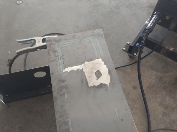
I kept opening the manual bypass to reduce the motor current, and while this did work it caused a lot of pump cavitation. I found it strange that the pump suddenly stalled, instead of the breaker tripping on the motor, the current sensing chips legs exploded. I will add that this was not instant and clearly the breakers are not sufficient, or I really should have written that safety program.
These oil pumps also provided lubrication to the bearings inside of itself. If there is air in the system then there is metal on metal contact. Cavitation is a fast way to damage the bearings on a pump or even seize it. So while opening the manual bypass reduced the pressure, it also increased cavitation. Soon as my electronic bypass valve opened it dropped the pressure to zero on the high flowing pump. Since the manual bypass returned directly to the pumps inlet it meant the pressure was almost zero. With zero pressure in the pump there is no lubrication in the bearings which caused it to seize. The pump is not completely seized and does turn over, but, the motor cannot get up to speed.
Ultimately the manual bypass has to be removed, this also means the high volume pump needs to be swapped out. This is the part where I could return both the 3HP motor and the low volume pump. I could then suit my system to the 2HP motor I already have and with the return money I could break even. However, I don't have the original box for the pump, and I cannot use that pump for the 2HP. So I'll grit my teeth for now and pay out the extra expense. I will later break down the pump to see what kind of damage it has.
I also noticed at the fastest speed I could move the cylinder, the pressure was at 700psi, this is approximately 5HP, not a surprise the current limit tripped. It is quite difficult to gauge pump size since more pressure is required to force a specific flow rate through an orifice. The one thing I did not know with my design is how much restriction the valves, lines and cylinder would have on the system, clearly a lot more than expected. The trouble is that I can half the flow rate and then maybe find that the pressure drops so much that the motor is only pulling 1HP. I clearly need more expertise / experience on the subject, I chose to contact the pump manufacturer, the one I chose for the high pressure pump since they're North American.
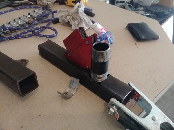
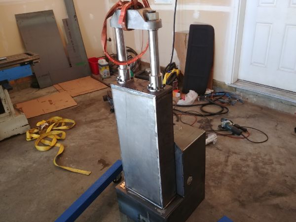
In the mean time I knew I would have to reinforce the top and bottom plates. I made a quick modification to the design, just two half-inch plates welded to it. I'm not entirely sure if I would keep this in the final design, I guess it all depends what it looks like.
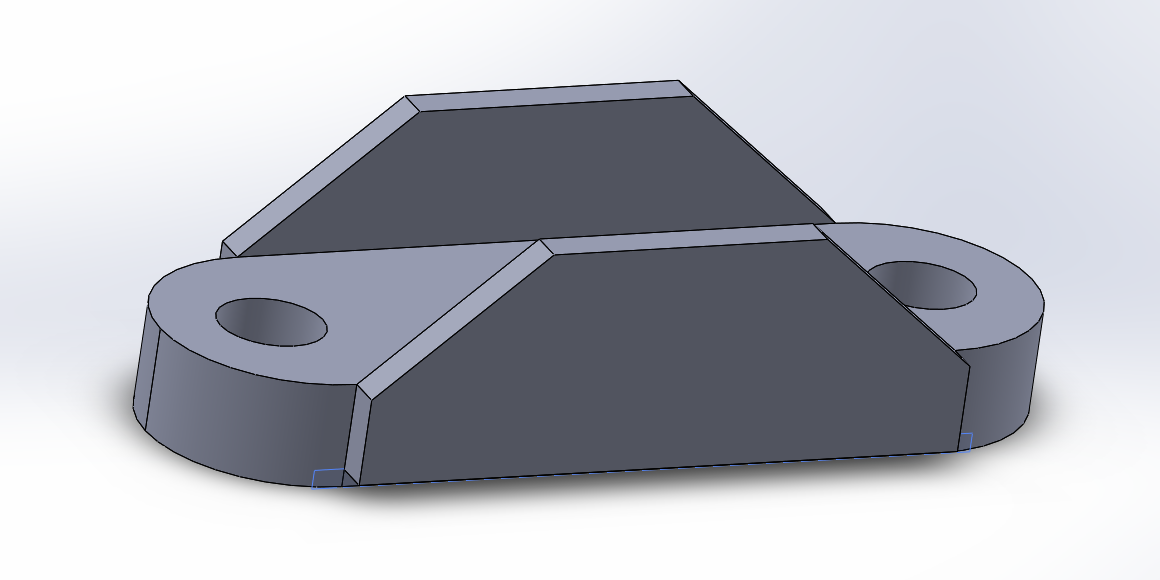
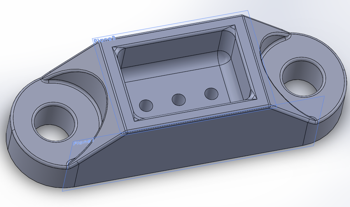
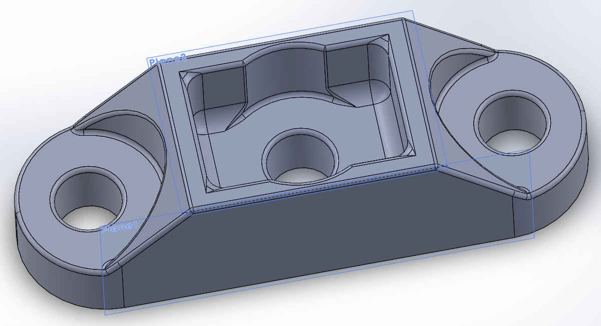
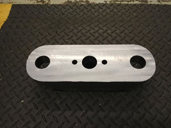
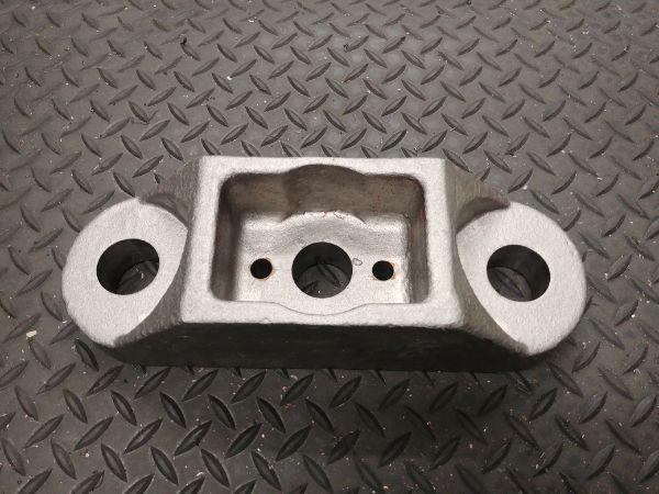
There is also a second option, but this all depends if there is enough interest in these presses and at what cost. That is to have the part cast in steel, the approximate weight of the part being 26.5 lbs. I feel a cast part looks a lot more professional than something fabricated together, it also looks a lot better when painted. I am lucky that I live close to a local foundry, what I don't know yet is the price of this part. A lot of the pricing would depend on if I provided a form, the weight and how complex the part is. Another option would be to cast it myself in aluminium, which is fairly easy to do but I'm not sure how it would hold up to fatigue, to cast in steel is simply too difficult. This is the one part I originally had to machine on a CNC mill, but at home I would have to invest in a cheap manual mill. The great thing with a cast is that I would only have to skim one surface and could have a preset boring tool for the holes, no multiple boring operations.
I decided to go ahead and contact the local foundry to see if this is a viable option. I would 3D print the forms, fill and paint them smooth. If the price does work out to be too much then I could always give casting them in aluminium a shot later in the summer. There are a couple of parts such as dies and forms for the press which would also be a lot easier to deal with cast. Often machining from bar stock can be a labour intensive process. The more I can fit into a batch, the better the price will be.
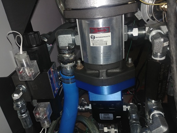
I got a reply from the pump supplier educating me that there was a simpler way, and sent me some documentation. I had originally been given false information from a hydraulic equipment supplier, that the high flowing pump used a relief valve. The truth is that the valve is known as an "Unloader Valve". The valve is connected to the high flowing pump and a pilot connected to the high pressure pump. When the pressure reaches a preset amount, usually around 650psi, the pilot moves the valve closing off the high volume pump and re-circulating the fluid. So it basically disconnects and unloads the high flow pump to save energy.
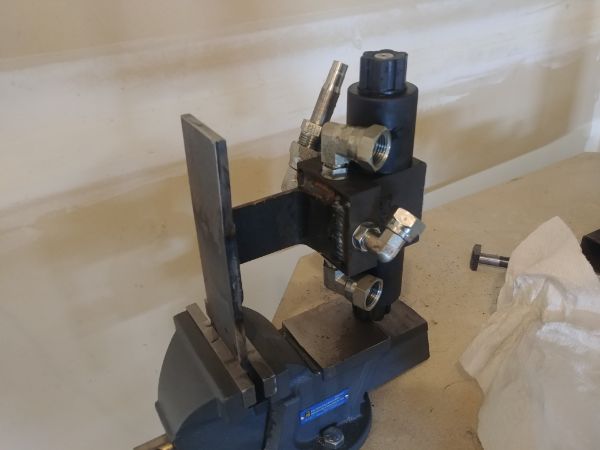
With this information I managed to get an off-the-shelf pump that should just about be ok for my application. I calculated that the high pressure pump would max the motor out at 3000psi, this is cutting it close but hopefully it will be ok. This leaves the problem of that the press will move fast until it reaches a certain load, I want the user to be able to control high and low. So I added a valve that would allow normal operation and then a pressure relief valve in parallel with it.
So with normal operation the press will move fast until it hits a certain pressure. When the bypass valve is closed it means the fluid has to pass through the relief valve, the setting being enough that the pump kicks into slow operation. It also means with this design that I cannot overload the system like I could previously thanks to the unloading valve. It also means I can simplify the control electronics with completely removing the current sensing chip.
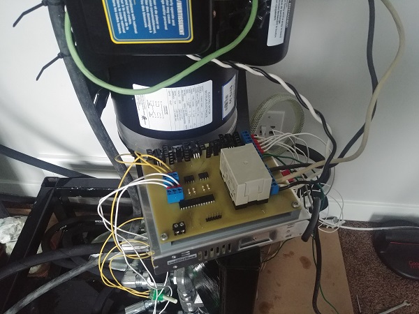
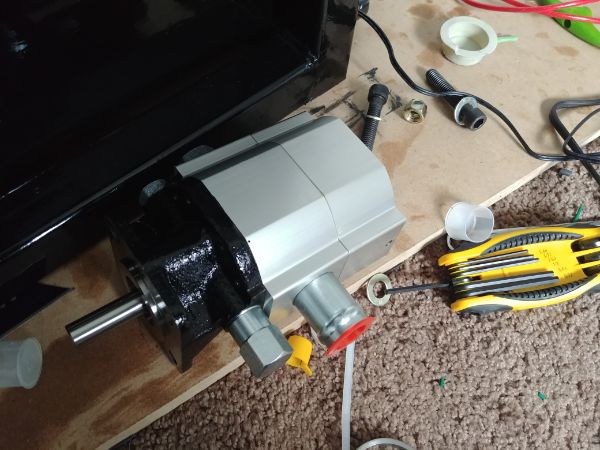
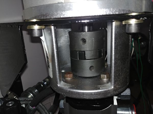
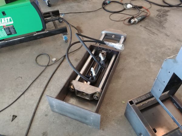
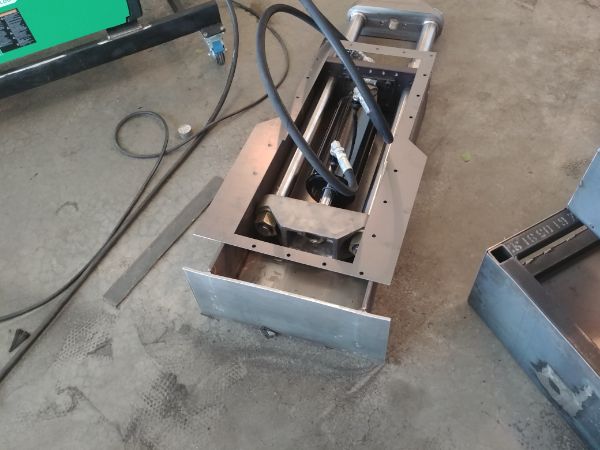
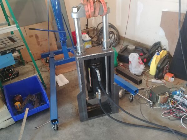
The pump required a slightly different mounting solution but it is now a lot more compact. The motor coupling now fits properly since it has standard shaft sizing and overall this is a cheaper setup.
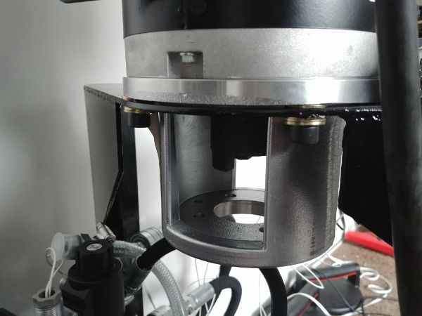
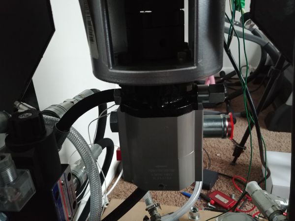
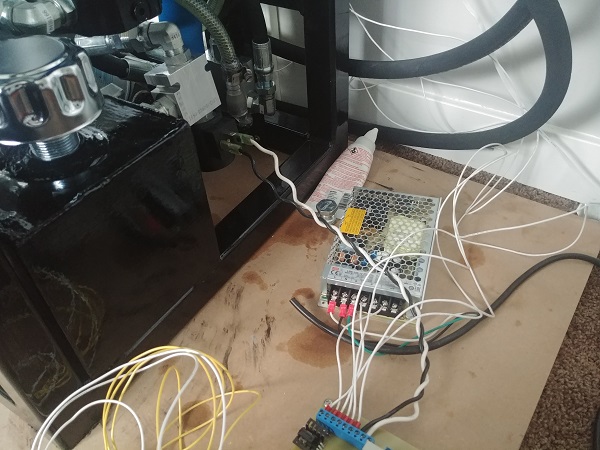
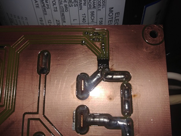
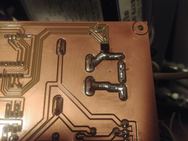
The pictures are a little dark since I was working on it late. Now that the overall length of the pump assembly is smaller it means there is more room to work on the hydraulics. I left the current sensing chip in place and just soldered over the tracks to bypass it. The chip is now obsolete in the design, that means I will update my circuit board design.
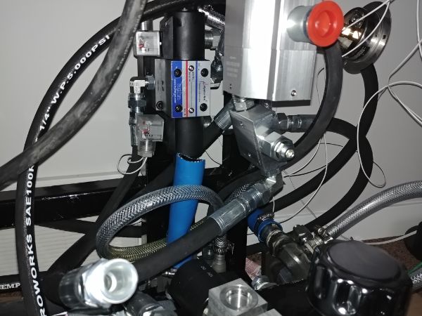
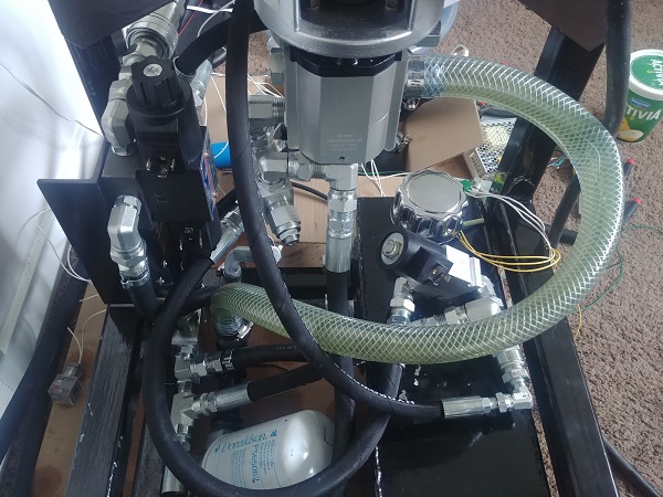
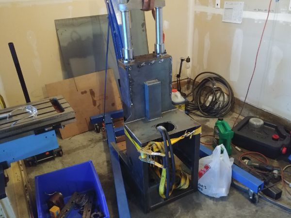
These pictures look like overall chaos but the system is now ready for testing. The pressure relief and bypass valves are left floating, while this is not a problem short-term it may become a problem in the future. Once I am happy with the overall design I will make sure all valves are bolted down correctly.
I updated the program so it would not read the current anymore, I also made the bypass valve stay open. I powered up the press to find my motor was still stalling but I could easily turn over the pump by hand. I stripped down the electric motor and checked all the connections, everything looked ok. After assembling it the motor started up perfectly. I believe the high torque must have twisted the motor frame causing the stator to rub against the rotor. This motor is of very cheap and flimsy construction, something I can live with in my current press but definitely not if I make them to sell.
I started up the press to find it operated a lot quieter and there was no pump cavitation. The cylinder moved up and down with no issues on the fast speed, it pulled around 500 psi. On the slow setting it pulled around 50 psi, I feel the bronze bushes in the press itself are now ready for some grease. Allowing the cylinder to move fast into pressing something showed the unloading valve kick in at around 700psi, it then moved slowly. The pressure reached the preset 2900 psi with no issues of slowing the motor or stalling. So overall the press is functioning perfectly, I am very happy with these hydraulic parts.
On a totally separate note I decided I would not need the potentiometer to control the direction of the cylinder. While this system does work I decided I would change it to switches instead, these have a much better wear rating than a potentiometer would. It does mean I have to update the circuit board again, but I am due to make another one. I was going to keep the second potentiometer as the timer control, but again I chose a different option. I will instead go with a 12-position rotary switch as this allows the user to select an actual number instead of guessing, but it does mean a lot more outputs used on the micro controller.
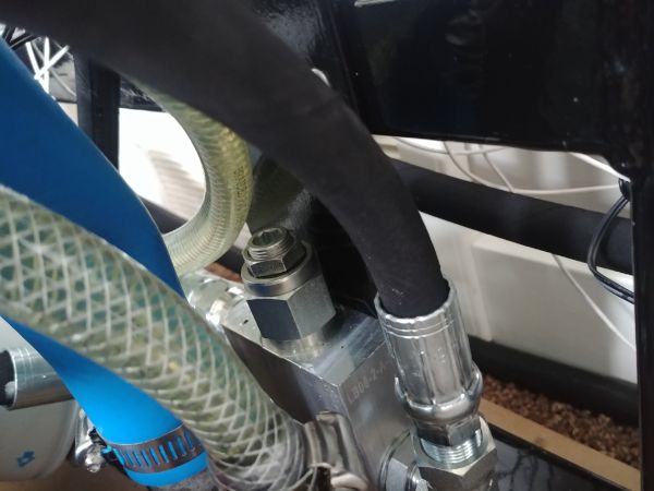
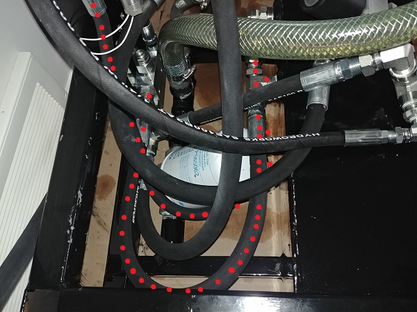
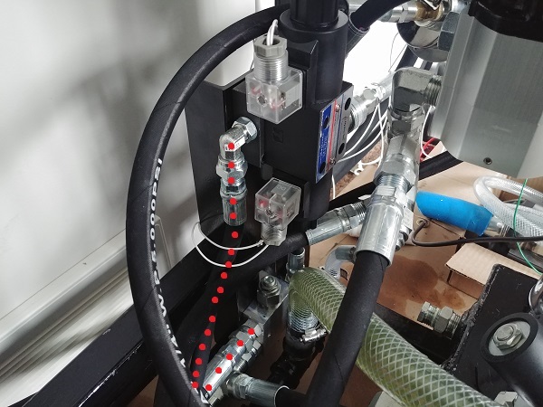
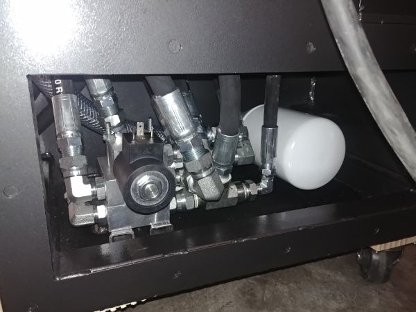
I started looking more at my hydraulic system now that it is working how it should. The first modification are these tank return lines, with red dots. Since these are returning fluid back to the tank there is no pressure, they also coil over the oil filter making it impossible to remove.
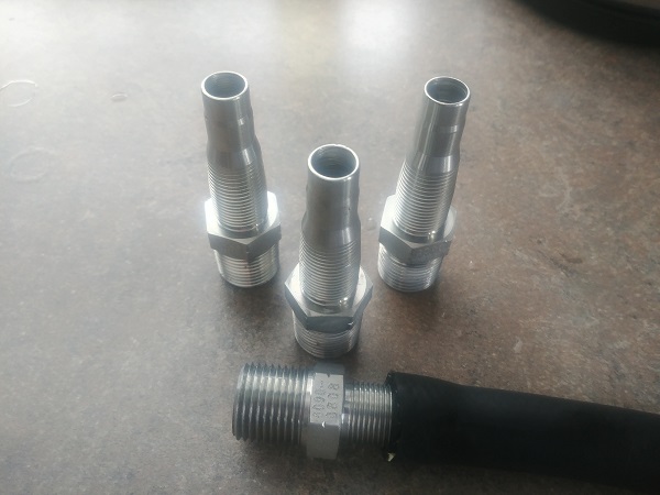
I did not need hydraulic hose, just a basic low pressure oil resistant hose. I changed a couple of the fittings and cut the hoses to the correct lengths, a more direct route. I got some hydraulic hose barbs because they still needed to seat properly with the hydraulic system, it meant placing them in a lathe and shaving the threads off where the hose pushes on.
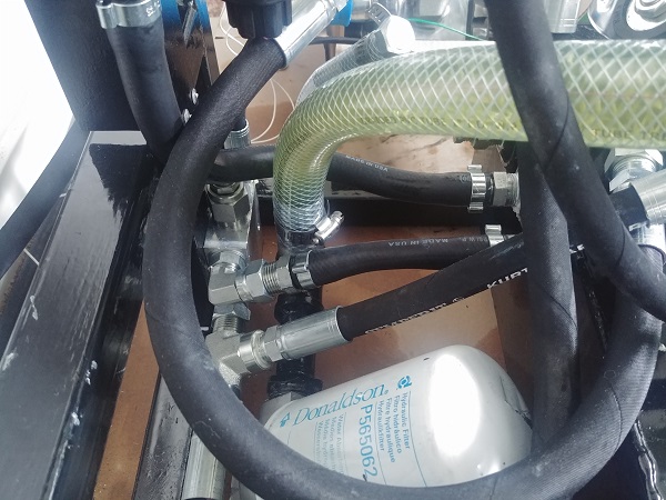
I used ear clamps to hold the hose in place, this solution looks a lot better than long lengths of hose coiling around, the tube is also a lot more flexible.
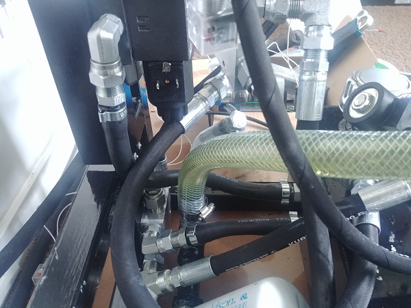
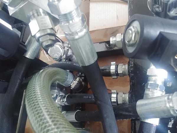
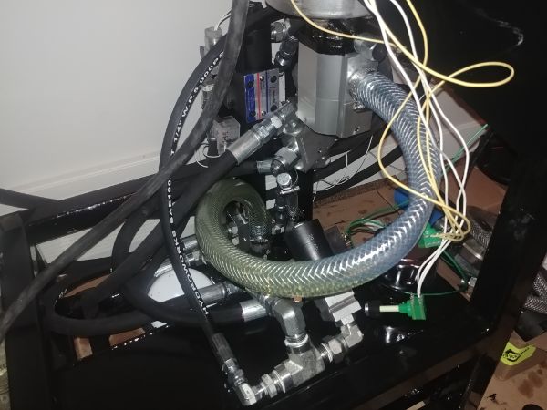
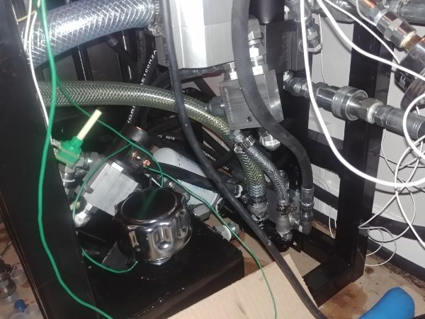
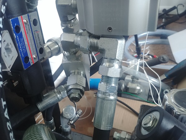
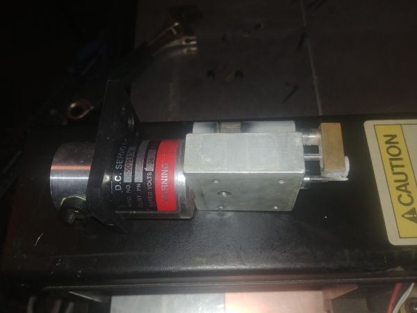
I added an extra fitting I had spare to the pump pressure regulator, this is so the hose would fit better under the frame. The last picture may still look a little messy but consider the black hose in the middle is for the pressure gauge, this will eventually be routed to the front of the unit. The braided clear hose needs a couple of elbows or some more flexible hose to stop it from kinking. The solenoid valve rests on the top of the hydraulic tank, I did originally want to re-route it. I instead thought it would be easier to weld a bracket on top of the oil tank to secure it properly.
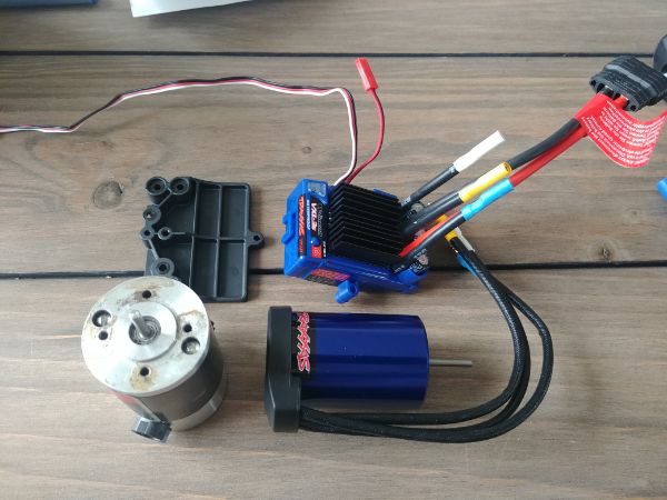
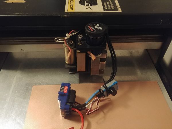
I had re-designed the control circuit board since I changed how the press would operate. I started to engrave the PCB when the spindle motor failed. I chose to upgrade to a RC car motor which can spin up to 45,000 rpm.
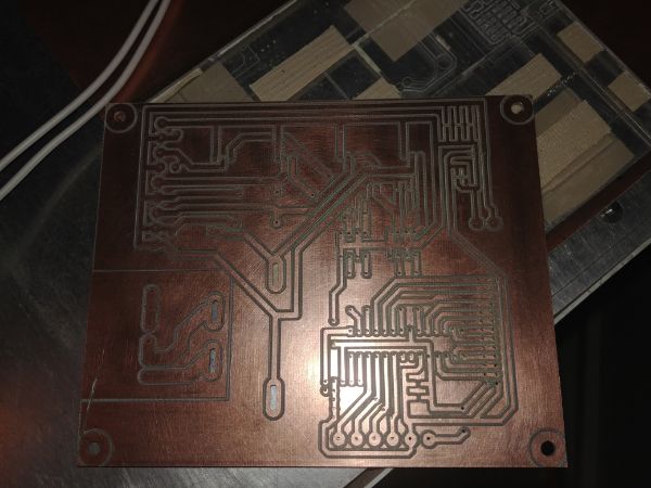
I was in a little bit of a rush to get the board done, otherwise I would have made something to hold the motor controller. In the end I got the circuit board engraved but not quite to the standard I would have liked. Since I had to switch off the mill for a couple of days it meant the machine lost its position, maybe I should get the homing switches connected. The isolated area was milled out a little larger than I would have liked, it meant some of the pads were not large enough. I also had a little mishap with cutting out the board, other than that it should function just fine.
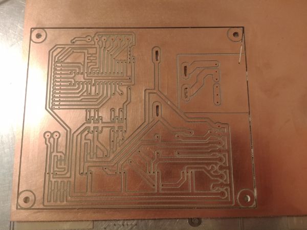
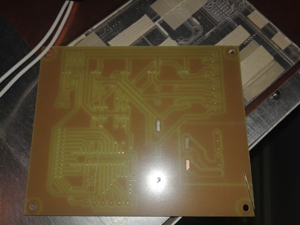
The board at a distance looks just fine, it's the soldering that may not look so good.
I removed some of the components from the previous board with a de-soldering station, that being the relay and terminal blocks. I upgraded to a different type of MOSFET to control the valves, these have such a low on resistance that they don't require a heat sink. The voltage regulator still would since they are so inefficient. I also added a large electrolytic capacitor to reduce any voltage spikes caused by back-emf from the coils. The soldering came out pretty good but the holes were definitely too big for the chips and resistors.
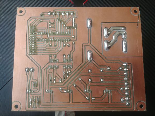
I cleaned the traces to remove flux and then coated it with conform al coating. There are two ribbon cables on the top of the board that will connect to the foot switch and selector switch. I soldered these on directly and then applied some hot glue to prevent breakage. The problem with soldering wires to a board is that the solder wicks the wires and makes it very brittle. Even a small amount of movement will cause the wires to break off. A more permanent feature in the future would be to use a header and socket with crimped wires.
I spent a few hours writing the new program, totally from scratch. This particular program is written in assembly to ensure it is robust and clean of bugs. This application does not require any speed which allowed me to slow the clock and make timer interrupts a little easier to calculate. I powered up the board and turned on all of the outputs to check for dissipated heat. The MOSFETs were all cold and the voltage regulator warm to the touch. These linear regulators are horrible for anything carrying much current or with a large supply voltage. For example my supply voltage is 12V regulated down to 5V, that is a voltage drop of 7V. The voltage drop multiplied by the current is the amount of power that needs to be dissipated. I often build a small buck regulator for any projects requiring current as they're super efficient, but that comes at a higher cost.
The rotary selection switch was programmed to have the following modes;
Position 1 - Off
Position 2 - Slow movement Up / Down via foot pedal.
Position 3 - Slow / Fast movement Up / Down via foot pedal.
Position 4 to 12 - Auto-press with timed retraction.
When the foot pedal is pressed it will turn on the hydraulic motor, a small delay, and then the directional valve. After ten seconds of no operation the hydraulic motor will shut off as a power saving feature. I believe that any longer may be unnecessary and any less will increase the switching cycles of the relay. I spent the extra money on finding a relay for this application, so I'm hoping it will last a long time. I may also look into a socket for this relay, yes it will cost more, but it will allow the user to replace it themselves.
I tested the operation of every single selector position, all the pedal positions and watched / listened to the relays / solenoids. The whole of the electrical system is functioning perfectly, that means I can look at making it a little more permanent. In the mean time I will work on a prototype for the foot pedal, to be 3D printed out of plastic at first. It may be possible that the inner workings in the final product may still be 3D printed, the overall frame will however be constructed in metal.
I wired the circuit board to the press and tested all of the selector functions. It seems that all is working perfect including the automatic return function. The only thing I do need to improve on is some of the delays for the automatic return as the shortest delay returns quarter of an inch and the longest delay is only three inches. In the mean time I have started playing around with some ideas of how the pedal will work, it seems like there may be quite a bit of prototyping involved. I will be looking for the shortest profile possible while maintaining simplicity and strength.
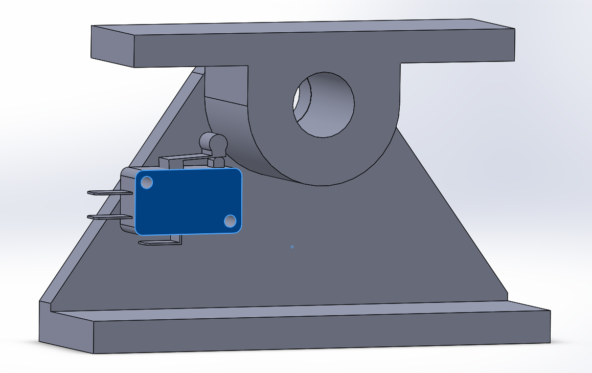
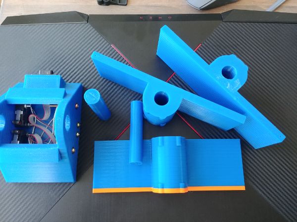
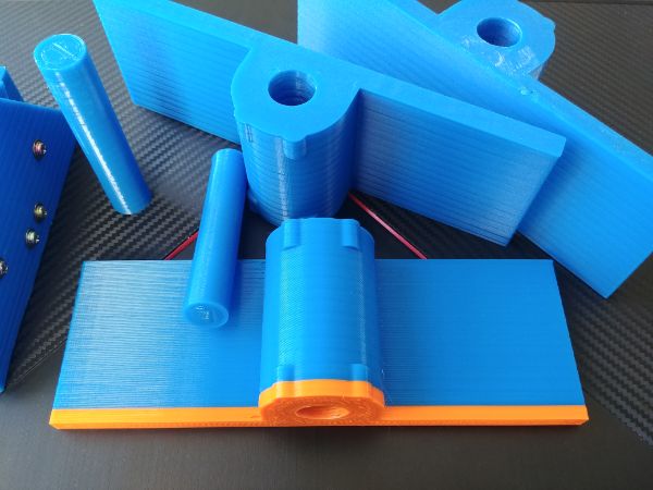
I left the design a couple of days to have a good think. I believe this is a good starting point with the intention of 3D printing a prototype. The only thing I have not included are some return springs as those will need to be sourced.
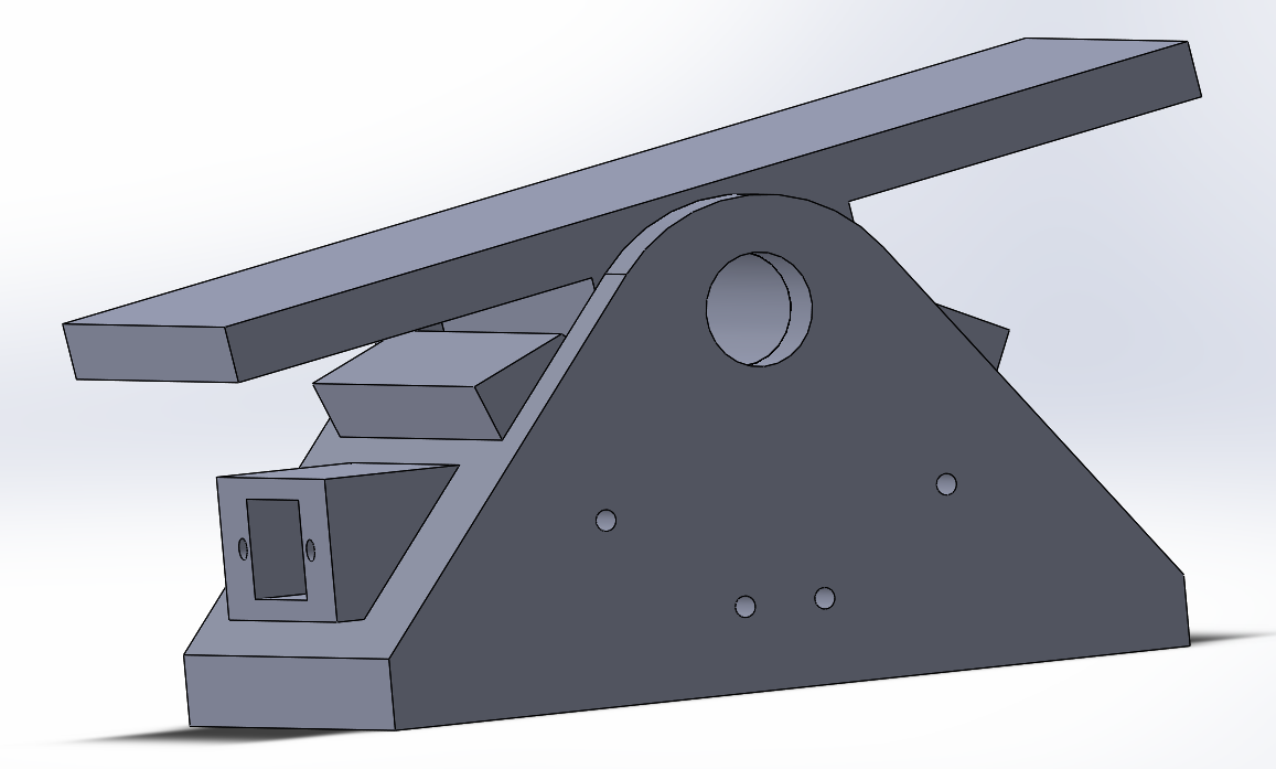
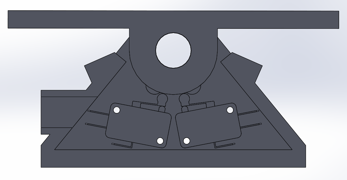
Here is a sectional cut of the pedal. There are a total of four micro switches which control both directions and both speeds. I made sure to include some stops and overall make it as simple as possible. While I sure would like to make the whole of this press out of metal, the pedal may be the one plastic component. I do believe it will be extremely strong and durable, but that may take some convincing. I could make it from a solid piece of aluminium, but that all depends on sourcing a CNC mill at a reasonable price.
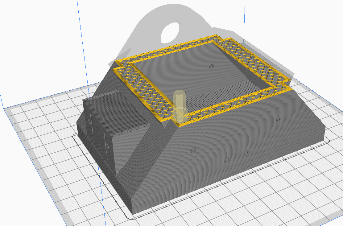
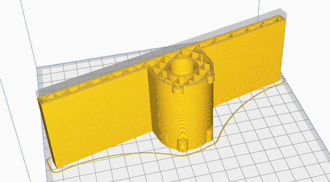
Some of these larger prints can use quite a lot of material or take a lot of time. I thickened the walls and reduced the infill in hopes to still keep it strong while reducing weight. Overall this print will take around 16 hours, hopefully without issues. That was not the case, I had to change nozzles and settings to stop the printer jamming.
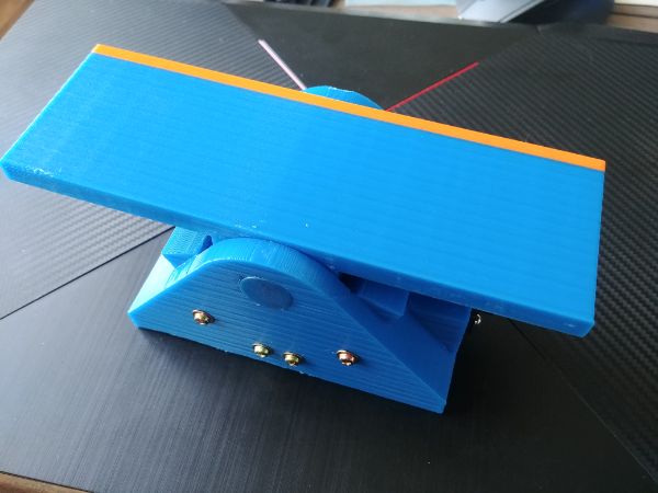
The pedal printed with no problems, I knew I would have to make a few revisions of this part.
The print came out pretty good, the supports were difficult to remove due to using a larger nozzle. I installed the switches along with the wiring. It took 3 attempts to get the dimensions right on the pedal, but accounting for shrinkage can be tricky.
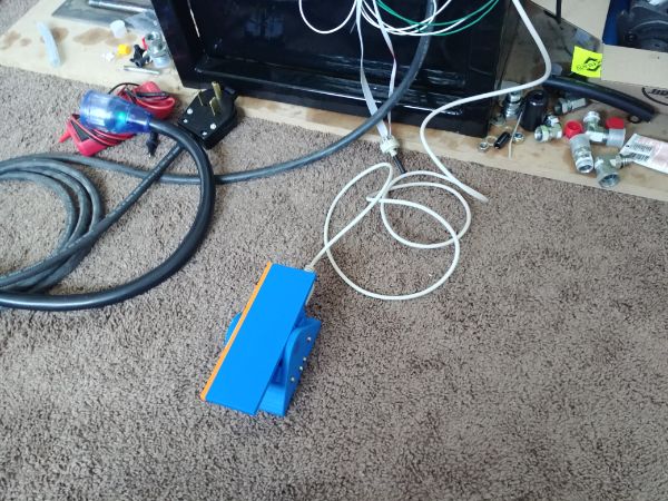
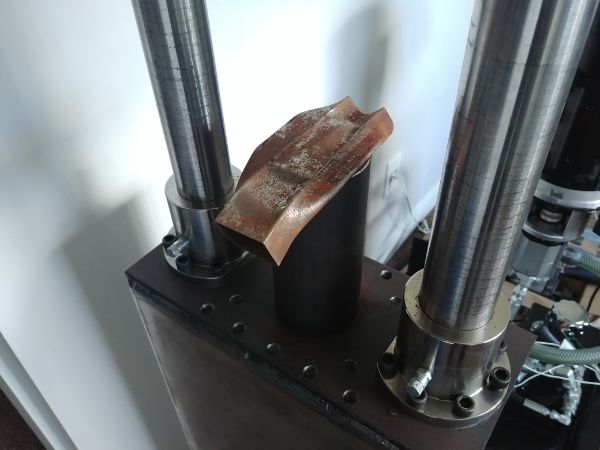
I connected the pedal to the press, everything functions perfectly. I had a little play crushing a few parts, 24 tonnes is a tremendous amount of force. It is quite clear that I am in need of the casts as both the upper and lower plate flex. The flexing pulls the pillars together and puts extra wear on the bushes.
I'm going through a complete re-design of the hydraulic unit, the press itself I'm happy with. I have also decided that the press should be one with the hydraulic unit. The press will still be removable, but the hydraulic hoses will not have a quick-connect and will be covered. A lot of feedback suggests that being able to locate them separately is not required. The most important thing is reliability and performance. I believe keeping the internals sealed will ensure a long working life, it also makes servicing a lot more pleasant when parts are clean. The environment will likely be a dirty one, grinding dust is a major hazard to the electronics.
I am currently in the process of trying to sell my project car, once sold I can really start to make some headway. I am going to use the money to get the appropriate machinery to make these presses, but I want a professional looking unit before I advertise. The pedal will be revised to be made from steel, it will look better suited to the environment. I will build a completely new hydraulic unit from parts used in the first. The big difference is that it will be enclosed and that all serviceable parts will be easier to access. All of the valves will be bolted down along with the electronics. The hydraulic tank has been adjusted so that there is more room for the valves but also has a slightly larger volume.
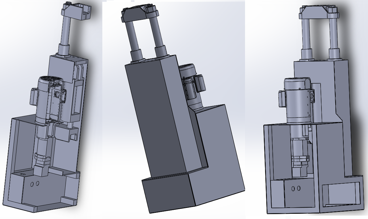
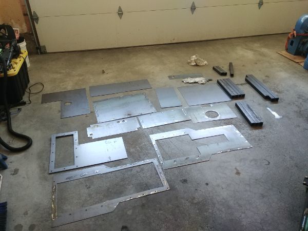
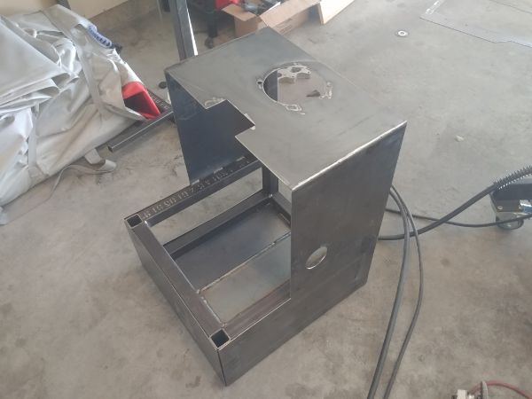
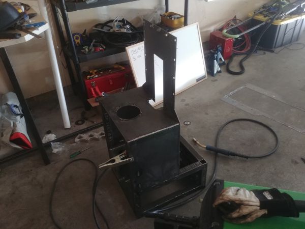
Here are a few pictures of the design so far. Having the sheet metal laser cut to size will sure make it easier to align everything.
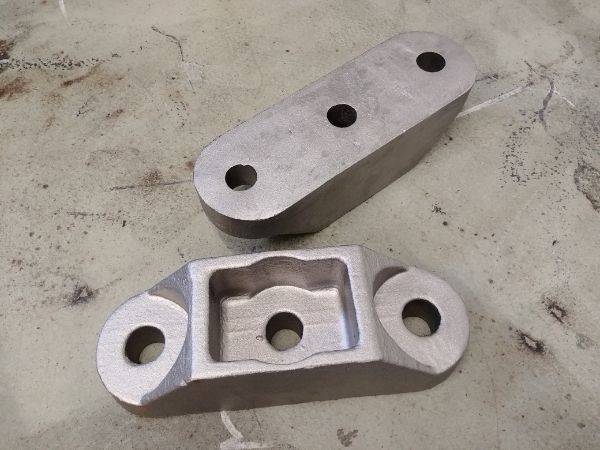
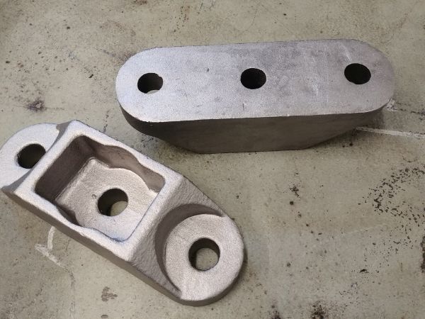
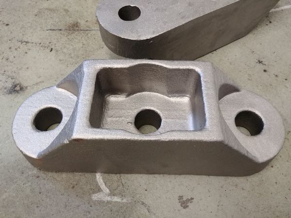
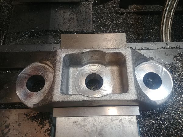
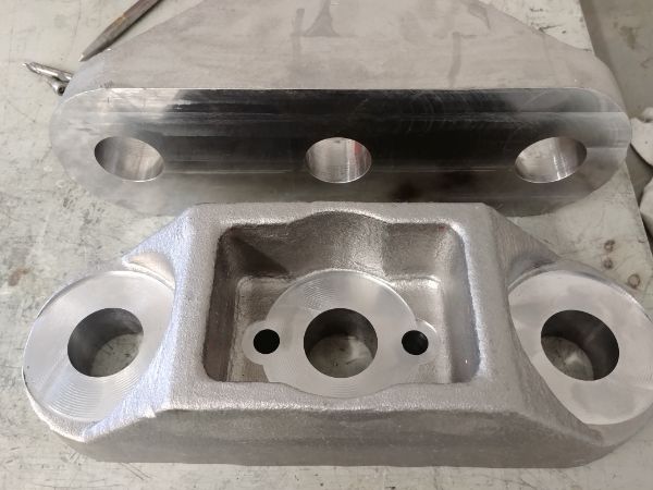
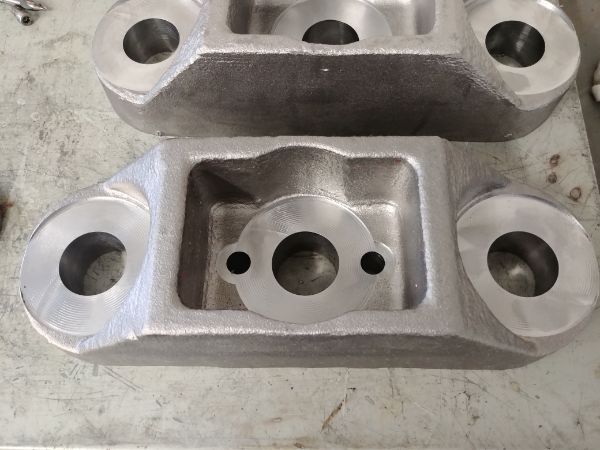
It's been quite a while since I did any work on the project, that's partly been due to not having the room. I did finally get the castings done so I could get something done. I'm really impressed how these turned out, they are cast in 1020 grade steel.
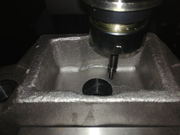
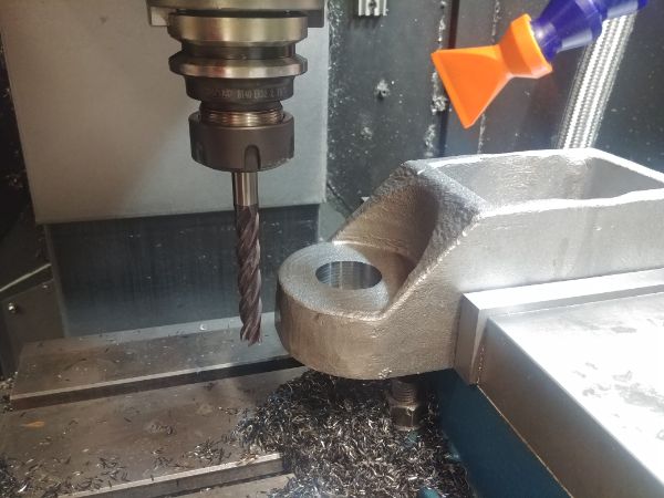
I set the CNC mill up to clean the faces of the castings.
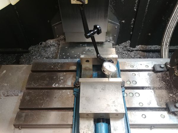
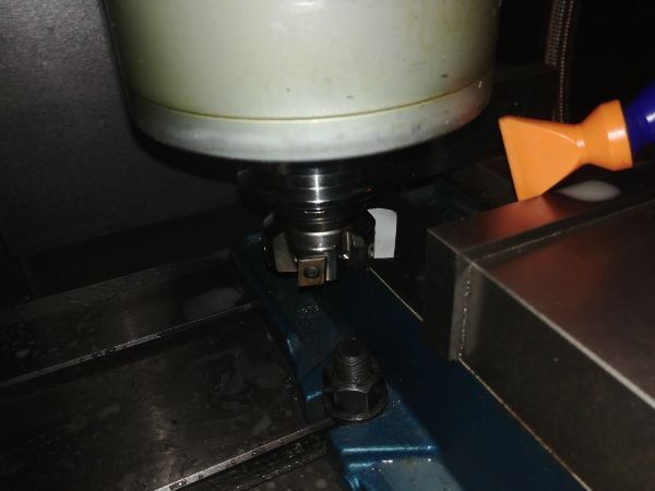
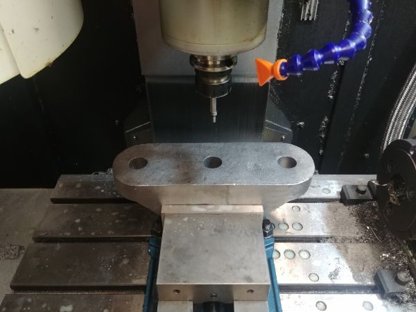
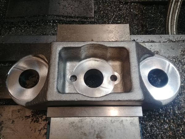
I milled out the holes to a much better clearance than before, now the pillars will not get stuck.
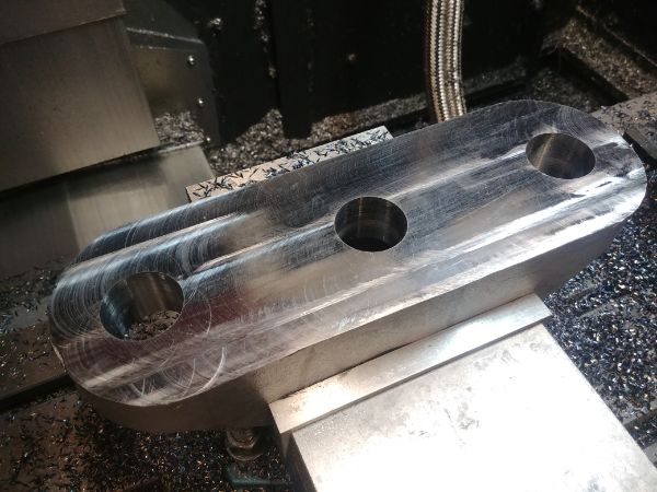
The top of the castings also needed to be cleaned up so the nuts would seat properly.
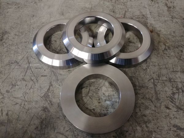
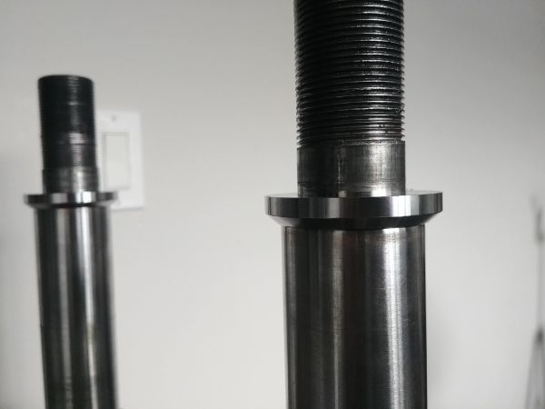
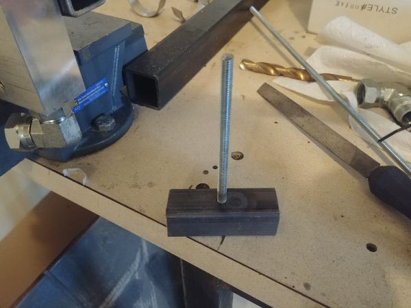
I made a couple of spacers from 4140 to help distribute the load better from the pillars to the castings.
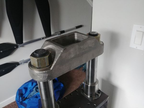
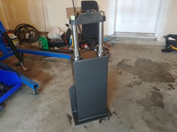
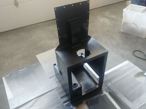
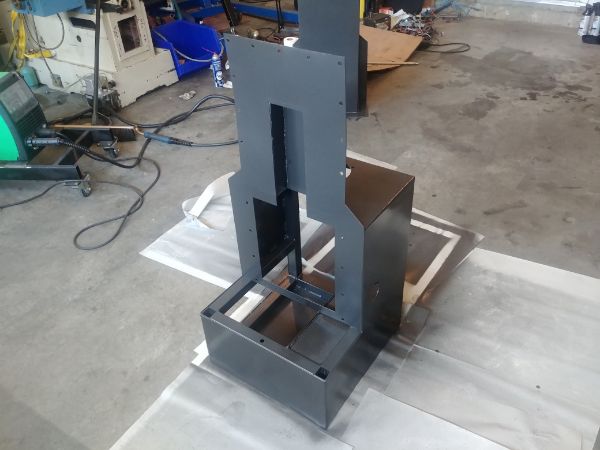
I am really happy with how the press is looking and it functions just perfectly. It is really clear now that the top and bottom plates do not flex nowhere nearly as much as they did before, it is certainly not visible. I now have the room to work on the press and have updated the CAD files ready to have some sheets plasma cut. I hope in the next couple of weeks that the press will be complete. I do have a couple of design revisions that I would not change unless I sold these. One is that the pillars would be changed to hard chrome plated hardened bar, this would increase the life of the bushings. The second revision is that the bush carriers would be screwed into the top plate, this would have to be thread milled. The benefit to this is I can use smaller metal, increase the work area and save a little time on machining.
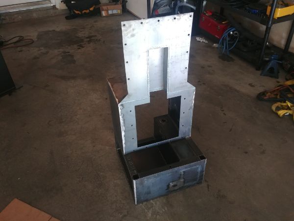
I got some pieces plasma cut to make the hydraulic unit and some box-section to make the frame.
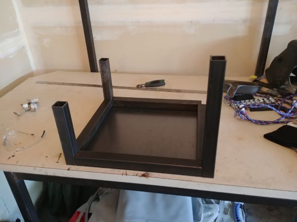
I made sure to make few tacks as possible to minimise the warpage.
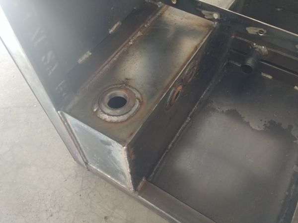
The areas where I had to make a full continuous weld was that for the hydraulic oil tank, this cannot leak.
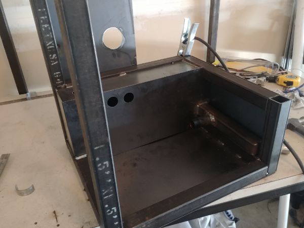
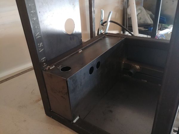
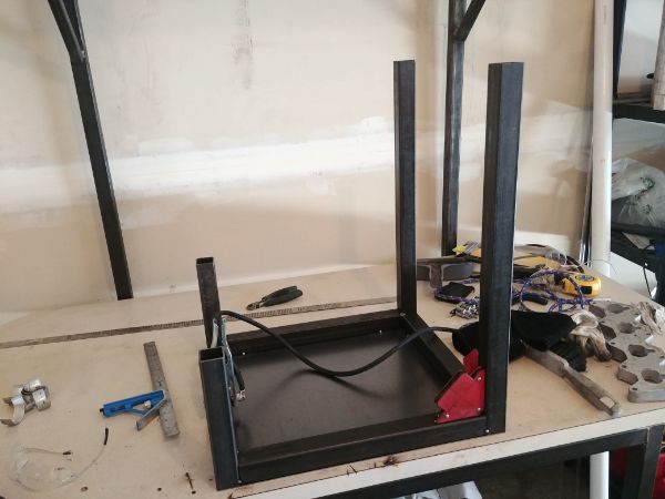
I had to cut a panel out of the front so I could make a weld for the oil tank, maybe not the best planning.
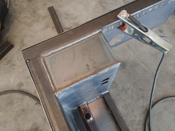
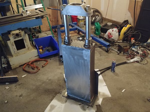
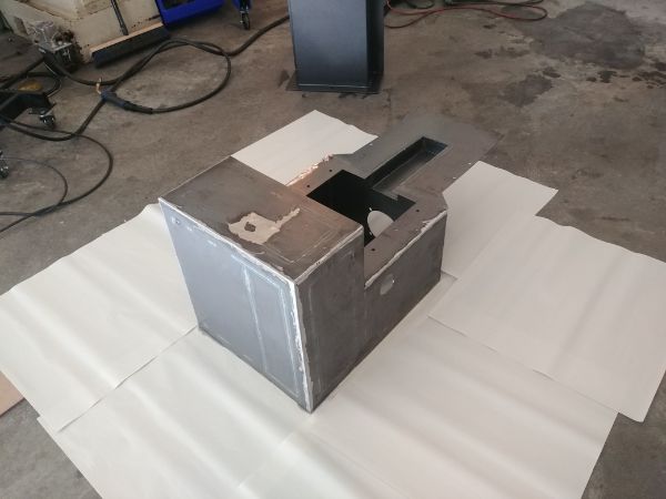
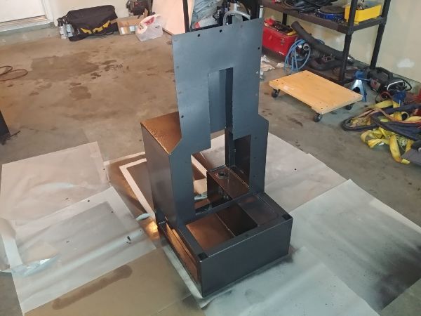
I finished off the hydraulic press itself and prepped it for painting.
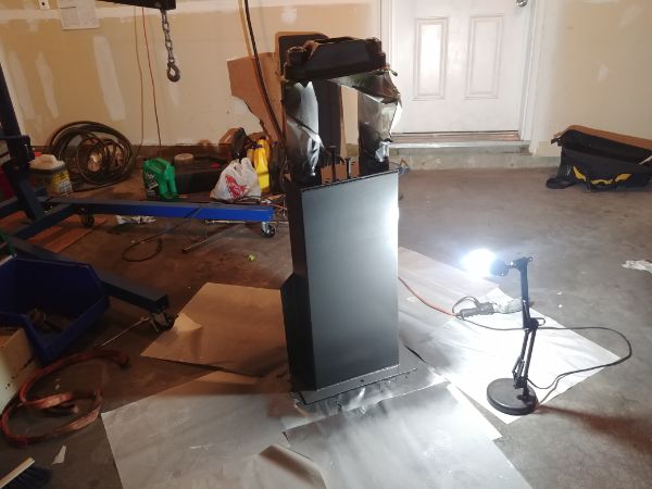
The hydraulic unit required a lot of welding which caused some distortion, that is all of the edges welded. I then spent some time grinding all of the welds back to blend them a little better, this was a very messy job. I decided that for the third revision, if there is one, will have all of the edges riveted together and some tack welds on the inside. This will cost a little more but will reduce the warping to virtually nothing, and I will not have to grind any welds.
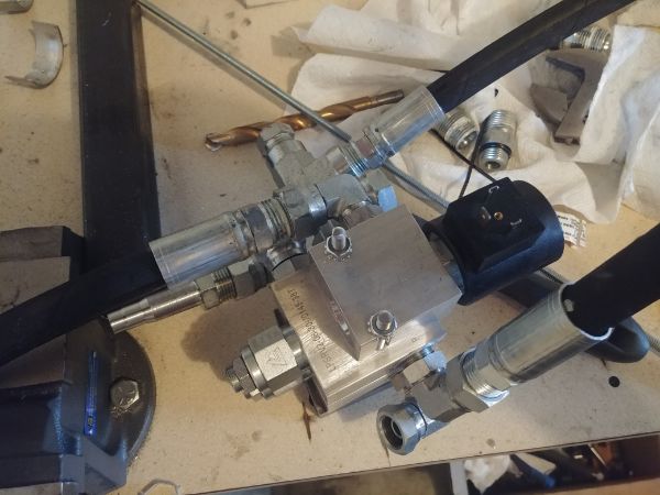
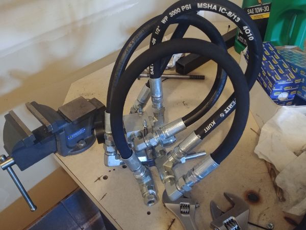
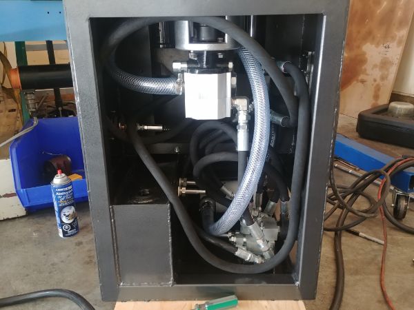
The valve work is definitely one part I'm not 100% happy with. It's not that it won't function fine, but it does look messy. I chose to bolt all of the valves together, this also reduced the number of mounting points needed.
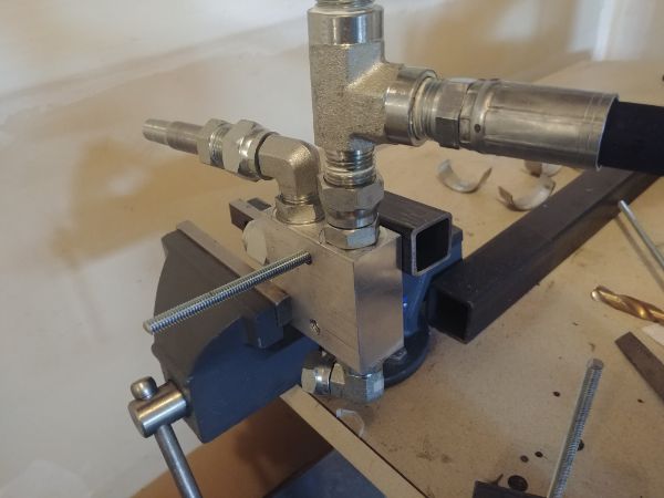
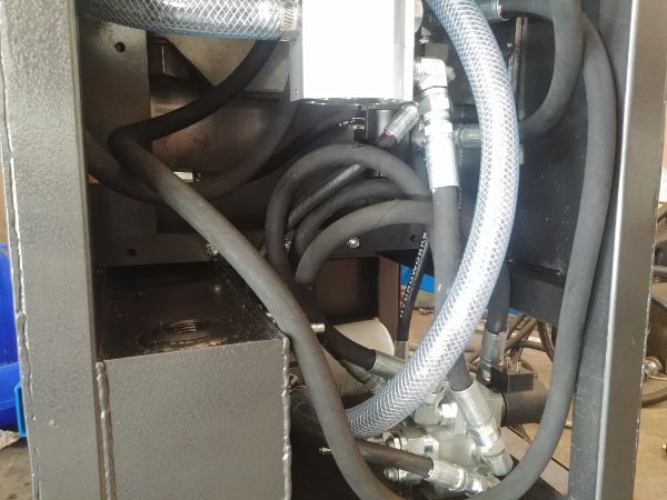
The valve work requires a number of hoses and fittings which makes it look rather messy, it also takes up a lot of room. On the third revision I will either machine a custom manifold or make some hard lines up myself.
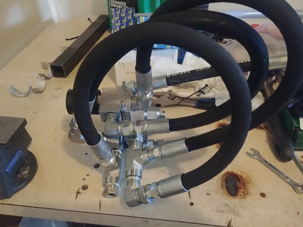
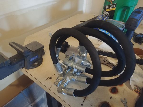
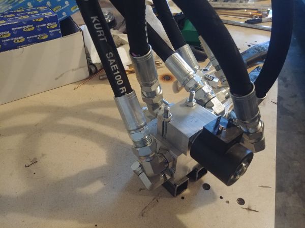
I got all the valves and hoses in the positions I wanted and then proceeded to install them in the unit.
At a side view the valve work does not look all that bad, just complicated.
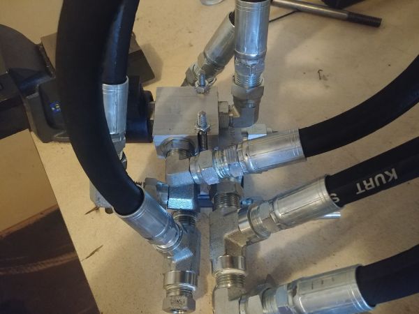
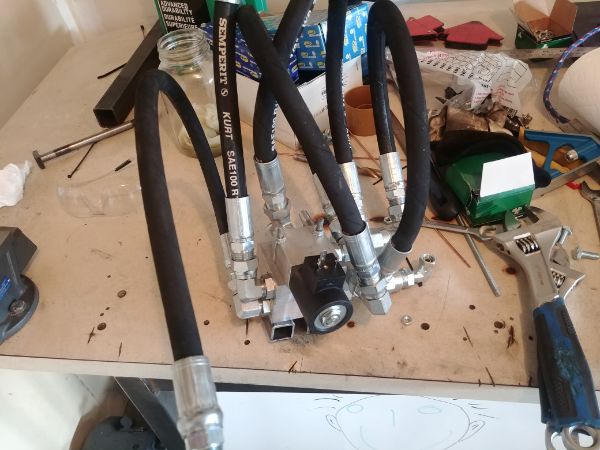
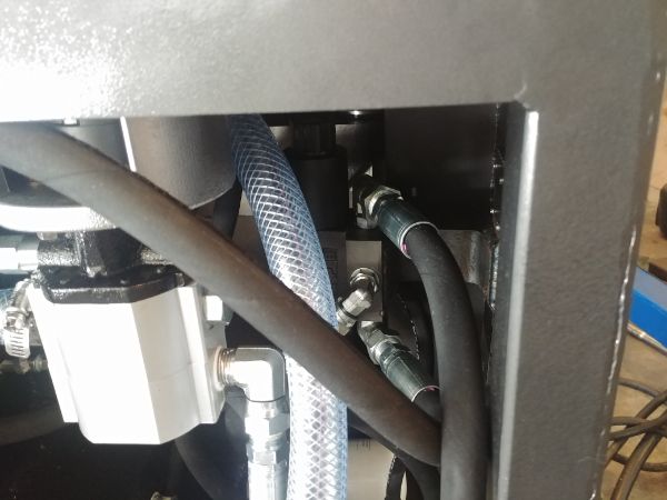
I spent a little time making a custom mount for the directional valve. This will be made slightly different in the third revision and will be welded in place before painting. The whole of the hydraulic system is complete apart from two return hoses. I had laid out the hoses in a way to reduce bend radii and make room for servicing. There are three hoses that loop back into the same valve assembly which takes up the most room, hard lines will look so much better.
The press is very close to completion. I need to install the electronic and electrical system, I have not decided whether I'm making a third revision of the circuit board before I do so. I also need to drill some holes in the frame to make room for rivet nuts, I can then bolt the cover panels in place. Then it's just one final revision of the foot pedal and the press is complete.
Hello, if you have enjoyed reading this project, have taken an interest in another or want me to progress one further then please consider donating or even sponsoring a small amount every month, for more information on why you may like to help me out then follow the sponsor link to the left. Otherwise you can donate any amount with the link below, thank you!