Engine Simulator
The idea is to make an engine simulator rig so that I can test out my modular ECU system before I wire it to my car. An engine is very similar to a very powerful compressor, the intake can reach very high vacuum levels. I don't have the required power to do this so the rig will be based for a MAF setup and therefore I will only require air flow. I can however build a miniature vacuum system for a MAP sensor that replicates manifold pressures.
The simulator needs to incorporate the following sensors;
Crank Position
Cam Position
Throttle Position
Mass Air Flow
It will also need to check whether the correct amount of fuel has been added for the conditions and also check the ignition system fires at the correct timing. It will need to;
Check Injector Output Duty
Check Ignition Duty and Timing
To make the rig accurate I will need to use the actual car sensors, this means that quite a bit of hardware is required. The main part will be a servo motor that turns a timing wheel for the cam position sensor, ideally up to around 7500rpm. The timing wheel will link to the crank timing wheel via a timing belt and timing pulleys. The ratio will be 1:2 so with an input of 7500rpm I should be able to achieve a crank speed of 15,000 rpm (for if I use my ECU for a motorcycle). The second part of the rig will be a fan that sucks the air through a throttle body and mass air flow sensor. There will be an accelerator pedal and clutch pedal so that I will be able to tune a flat shift.
The servo motor will control the speed of the cam and therefore the crank. The electronic module that reads the injectors and ignition timing will output a pulse width modulated burst that spins up the motor. Since the motor will require more power to get it to spin faster it will depend on how much fuel, ie the injector duty, and when the ignition fires. The rev limiter and flat shift will cut the ignition and / or the fuel depending on the tune.
Building It !
This is one of those projects that is mostly in my head and there is no real complete design. I will be designing a lot of the parts to 3D print as this will not only save time and money but also make the process a lot more forgiving if I happen to make a mistake. I will also say that there will be no particular order in which things will be done, it all depends on what I decide to work on at that time and also what time allows in my very busy life.
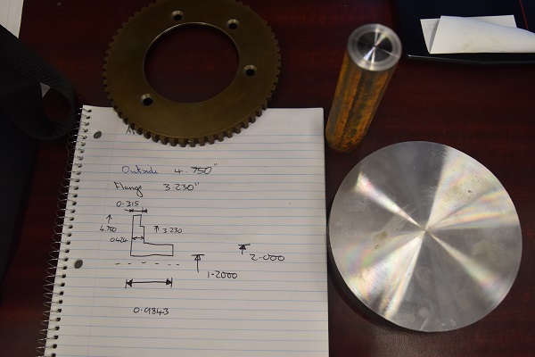
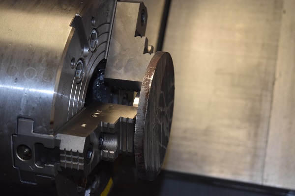
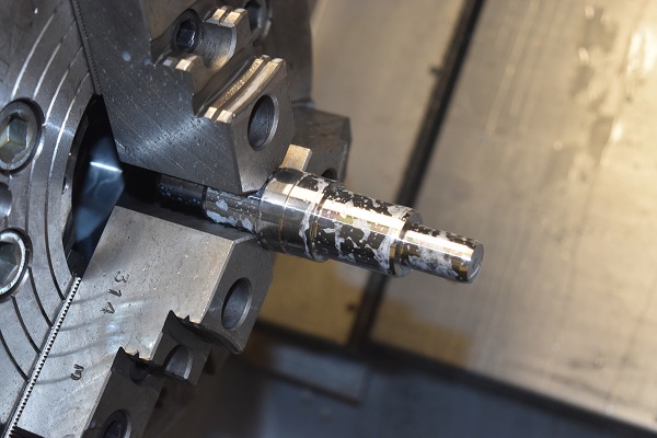
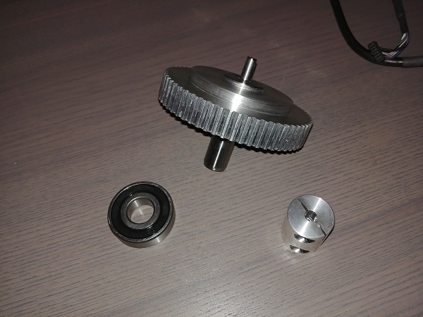
The very first thing I did was to get a crank timing wheel from the scrap yard, I literally had to pull and strip a complete engine to get this part. Luckily I think I'm quite adept at removing engines now and the whole process including stripping the engine only took me around 3 hours. I started off with a 6 inch round piece of 4140 steel.
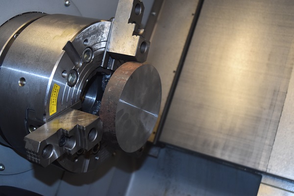
Some cuts taken to make the profile, only light passes since I was only holding onto 0.25 inch.
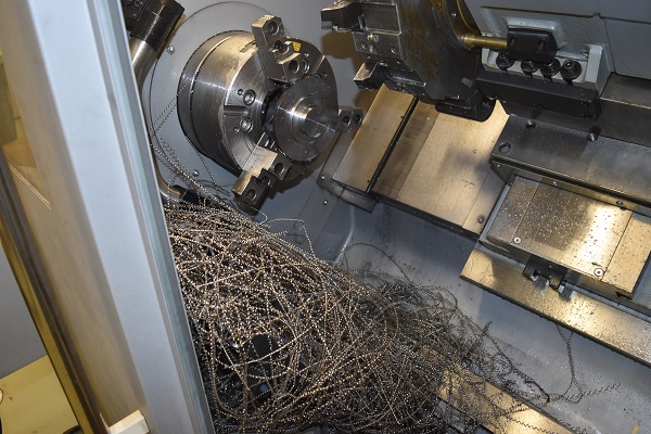
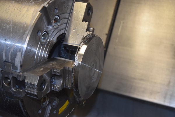
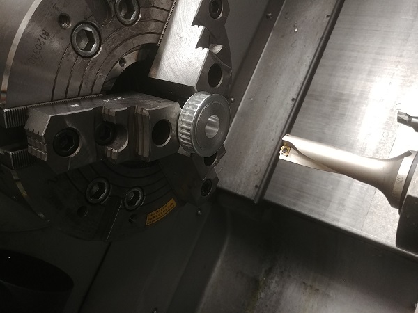
Flipped in the jaws to face the back and turn the OD to it's final diameter.
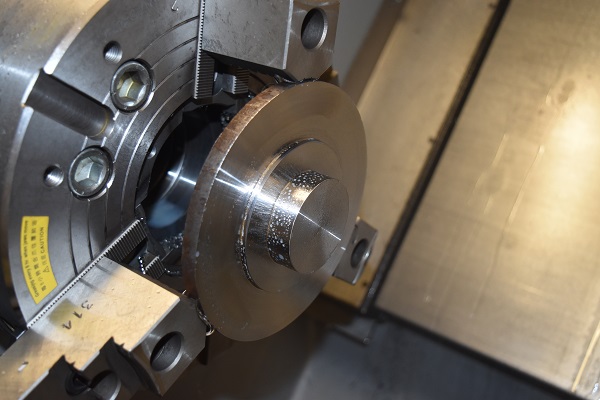
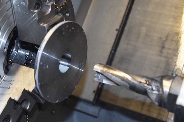
Drilled and bored using a U-drill, not it's ideal purpose but it worked. I used a piece of 4140 steel for the shaft, it's much easier to attain a bright finish than that of mild steel.
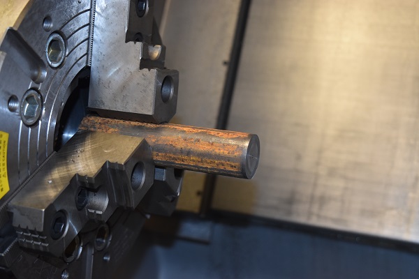
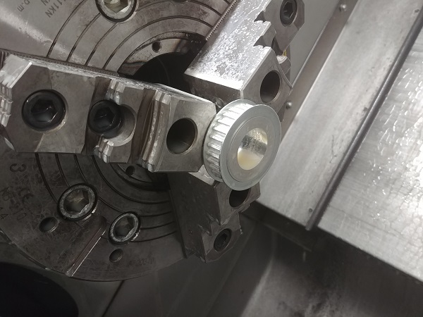
The shaft profile turned to suit press fit's, including the bearings too.
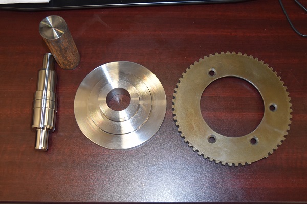
To spin this timing wheel will be a timing pulley, again I would choose to press fit it.
Drilled and then bored out with a bar, I aimed for a very tight interference fit so I wouldn't need to key it.
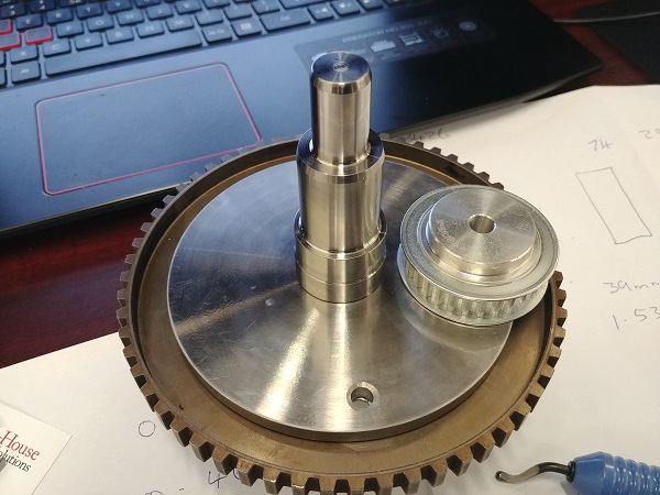
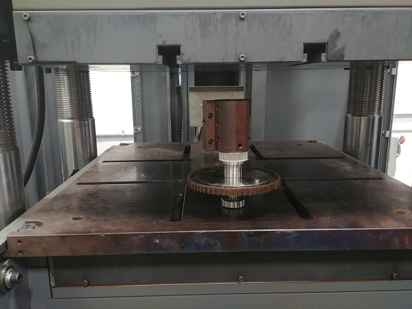
I used a hydraulic press to assemble it all together, the bearings also a very tight press fit. I bolted the timing wheel to the spindle, just one to keep it located. It also didn't help that my tap was done for after one hole, I think the TiN coating was more like gold paint.

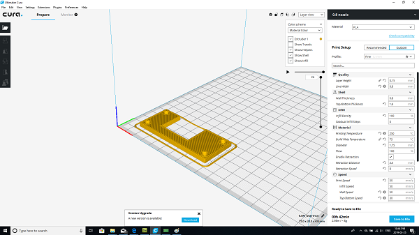
This engine simulator is being built for as cheap as possible so many of the parts will be 3D printed, it is also a lot more convenient since I don't have a great deal of spare time. I chose to make the bearing blocks for the timing wheel spindle first.
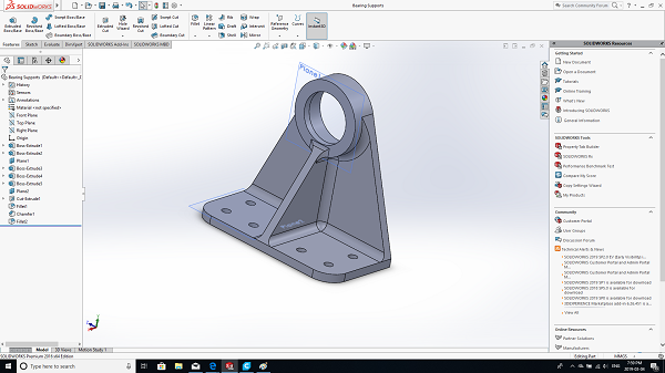
The material of choice being PLA since it's very easy to print with. The bearing was a very tight fit in the housing, PLA is also a very hard, rigid plastic.
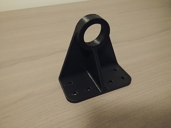
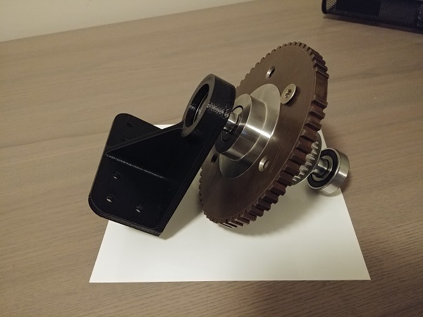
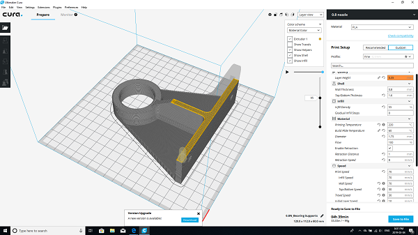
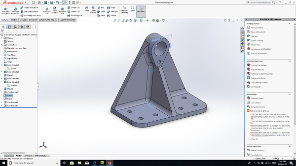
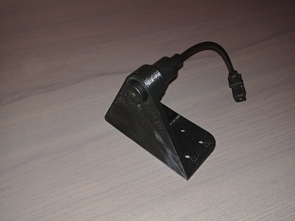
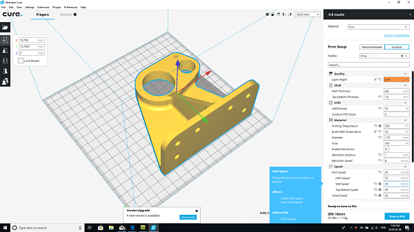
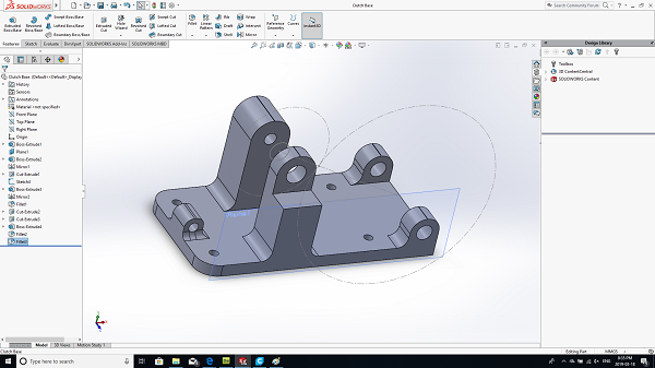
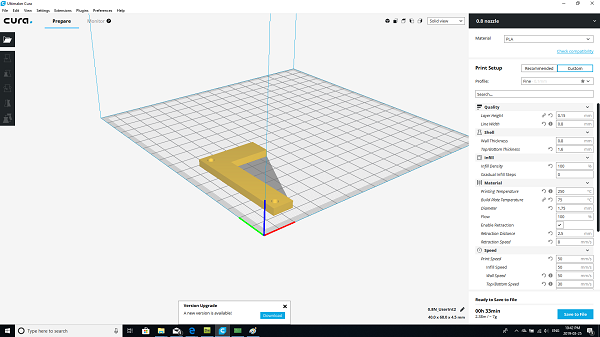
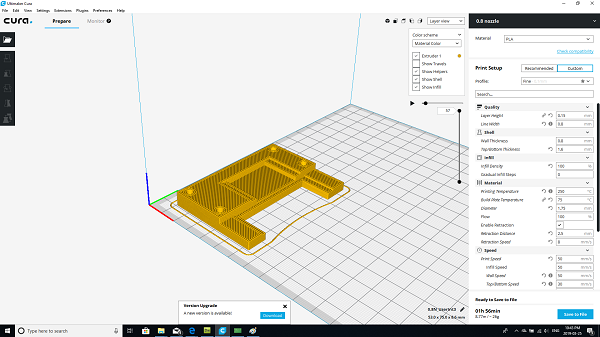
I next designed a mount for the crank position sensor, this would also have to be very sturdy to maintain a 1mm gap.
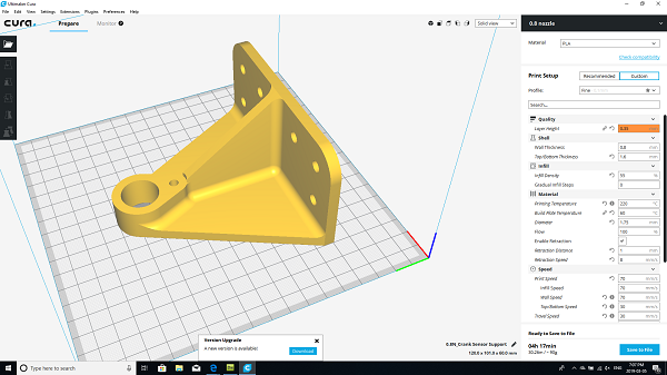
A second bearing block was printed before I printed the crank sensor mount.

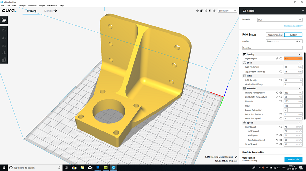
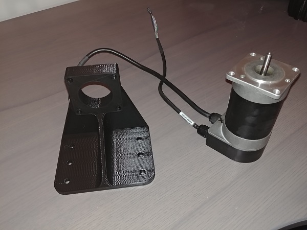
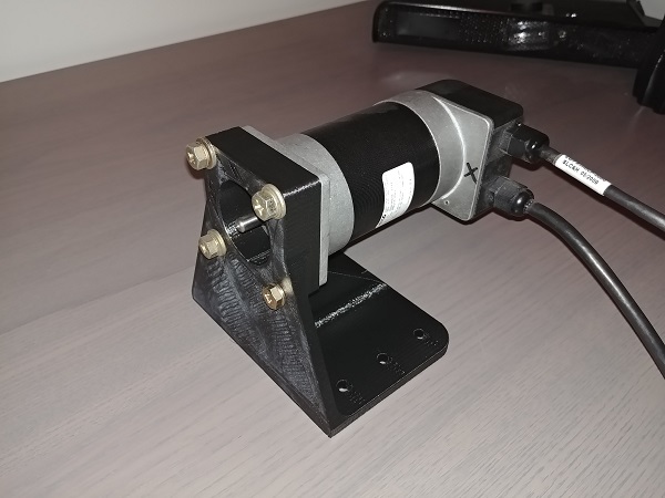
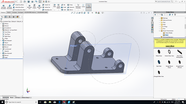
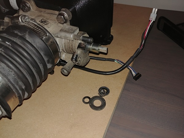
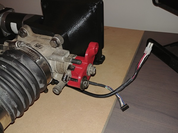
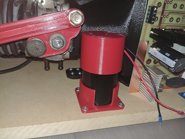
I chose to go with a servo motor to control the speed of the crank, it was also because I was given a couple for free. Here is the design for the servo motor mount, it will be used to spin up the cam side. This motor is rated at 6,000 rpm so at the crank I should be able to achieve 12,000 rpm.
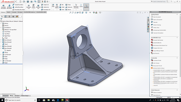
What I find really strange about these motors is that they are labeled as brushless DC motors. They are in fact a three phase motor with a permanent magnet rotor. It would mean that I would have to build myself a three phase servo drive later on, something I have not done before.
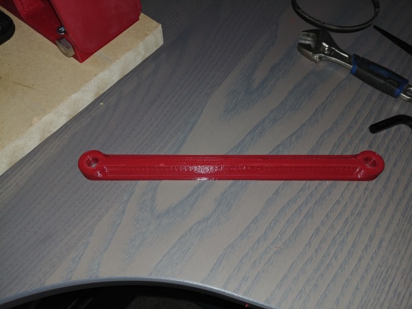
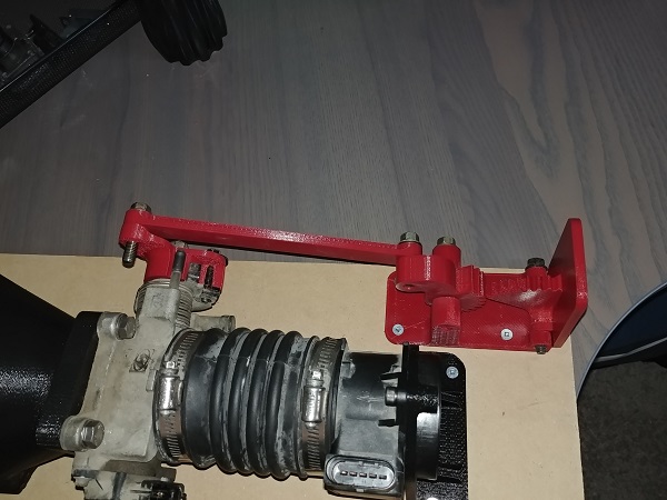
I next designed the bearing and cam sensor mount.

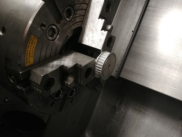
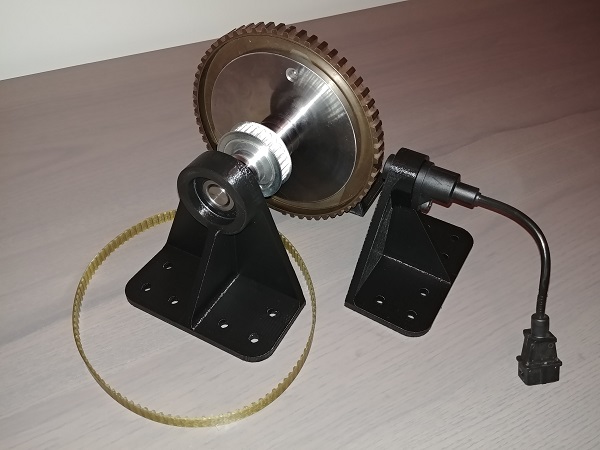
I also machined a spindle for the timing pulley and press fit it together.
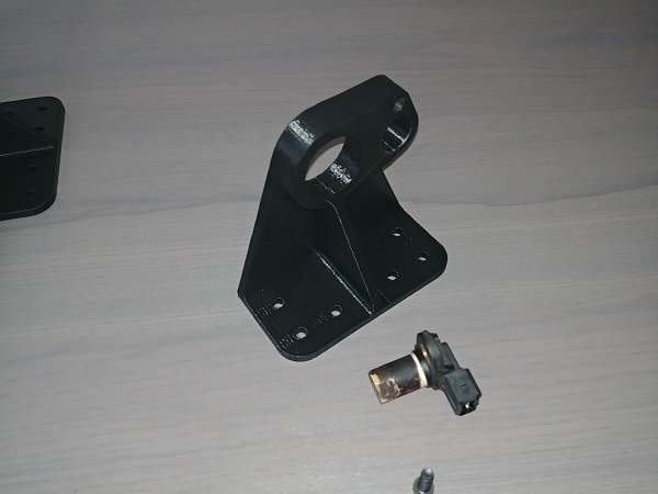
The cam sensor is used to tell the ECU when cylinder 1 is at TDC.
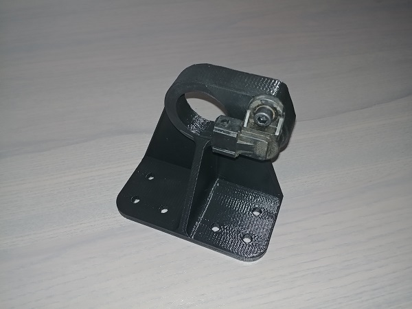
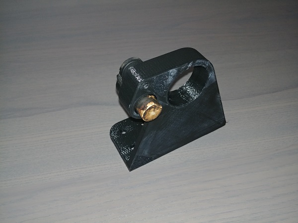
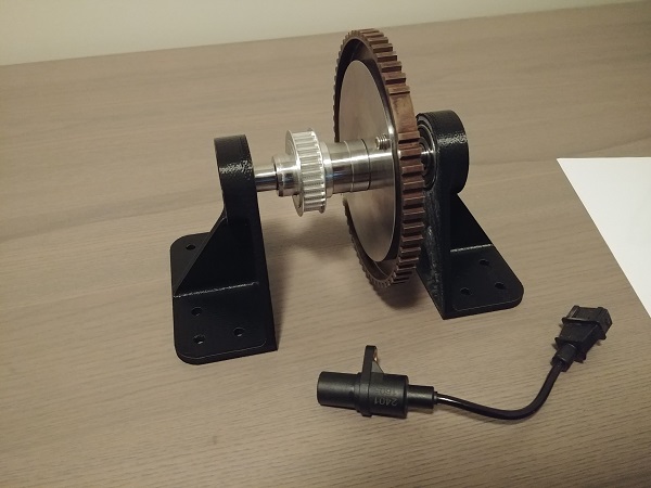
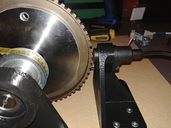
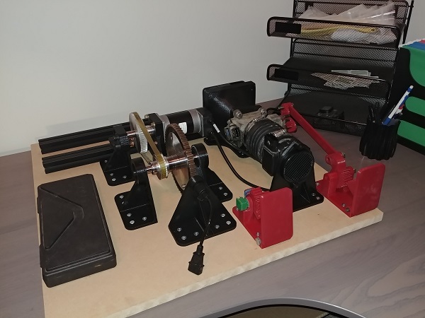
I got a piece of MDF board to build the rig on because it is cheap and very dimensionally stable. I used wood screws to hold everything down, here shows the 1mm spacing between the crank sensor and the timing wheel.
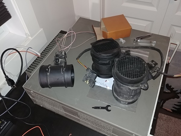
I got together some MAF sensors and also some fans to replicate the air flow through the sensor. In the end I had to accept that I would not be able to max out the MAF sensor without going to a very powerful and noisy fan. The purpose of this engine simulator is more to make sure that it reads the main sensors properly and that the timing is accurate.
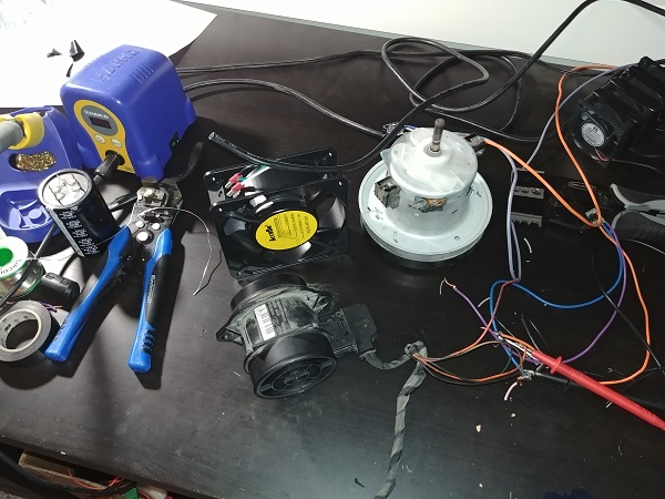
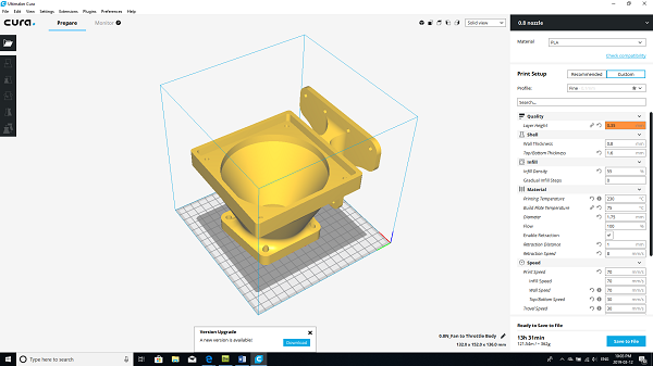
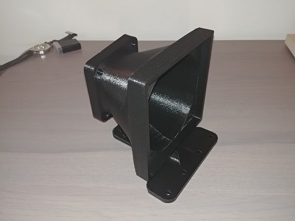
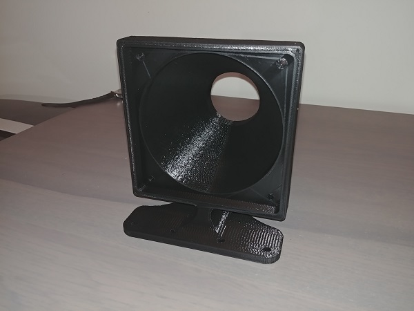
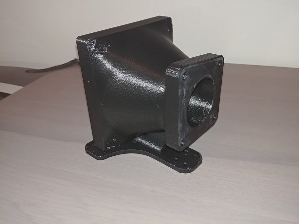
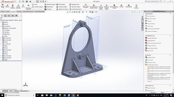
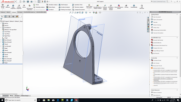
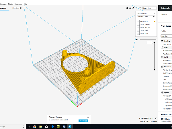
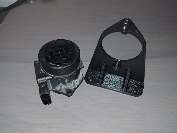
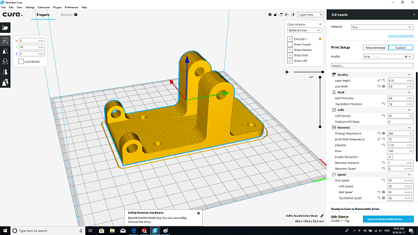
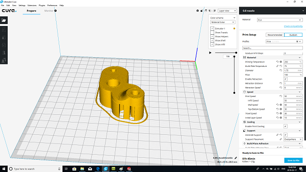
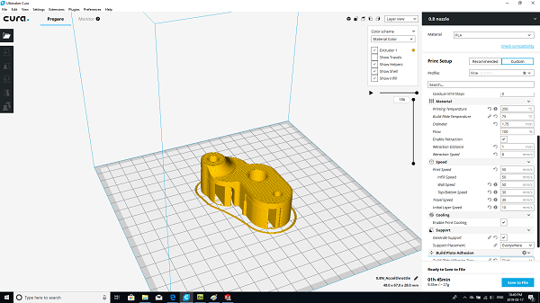
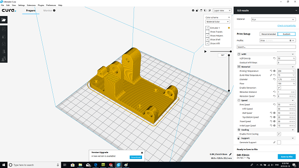
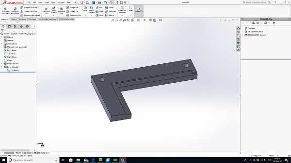
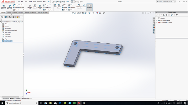
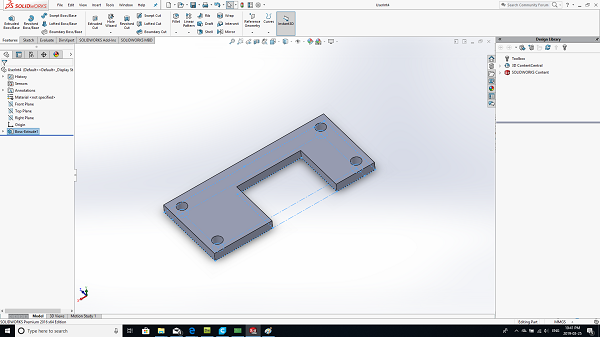
I designed a housing for a 120mm cooling fan to connect to the stock throttle body.
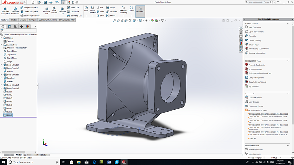
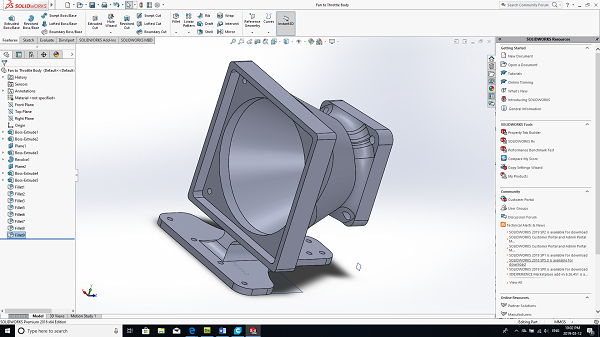
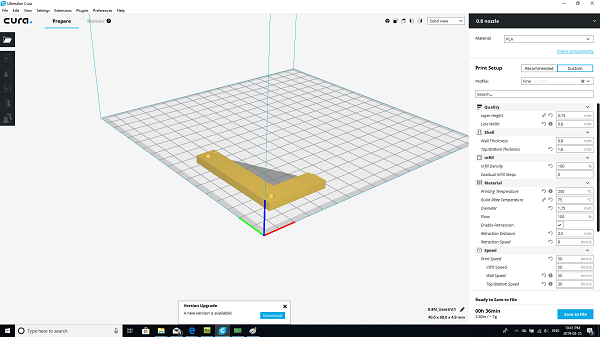
This was quite a large piece taking around 18 hours to print.
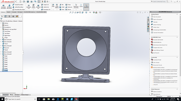
The part came out really good.
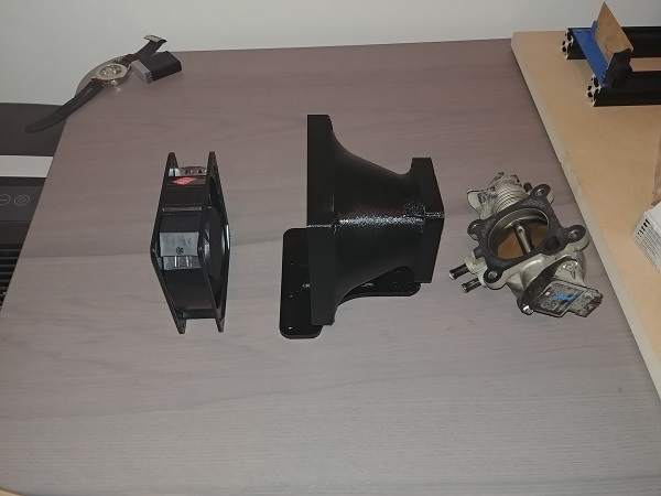
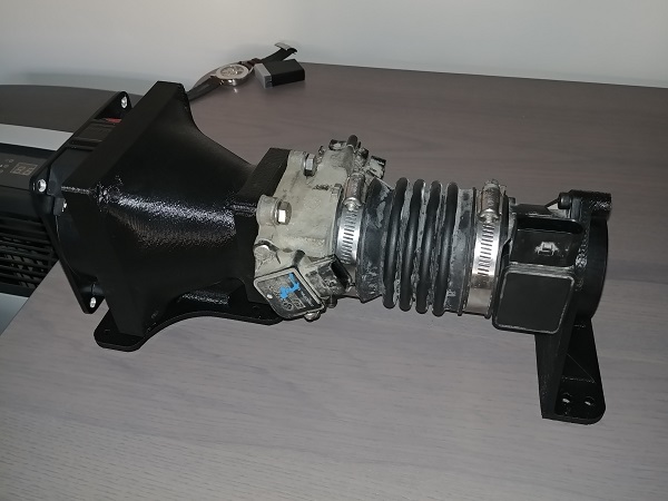
I found a random MAF sensor that would reach an ok-ish voltage with the current fan. It does not have to be specific to my car since I'm just checking out my electronic and programming skills.
The project is progressing nicely.
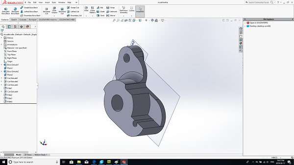
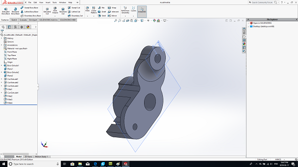
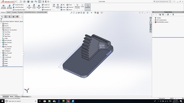
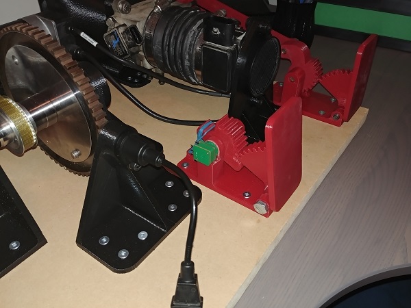
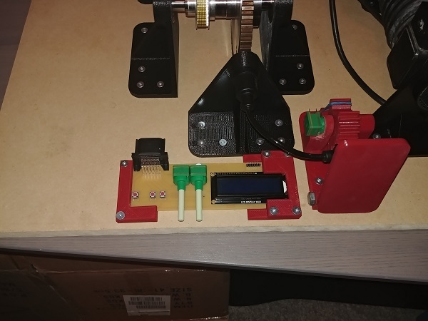
The simulator will require an accelerator pedal, so here one is.
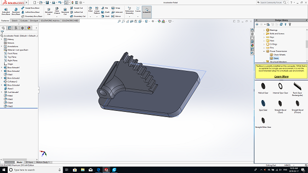
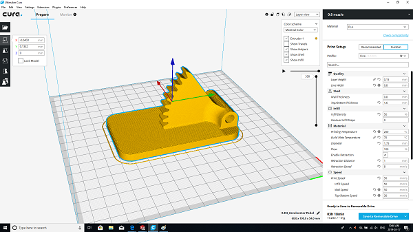

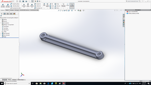
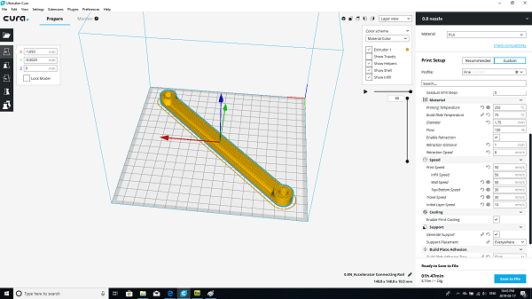
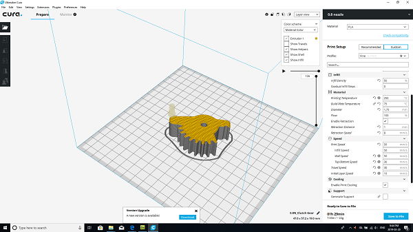
I chose to go with PETG since I had ran out of PLA, this is another nice material to print. PETG is also very strong and the layers bond very well meaning it is great for structures and load bearing parts.
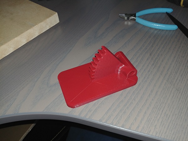
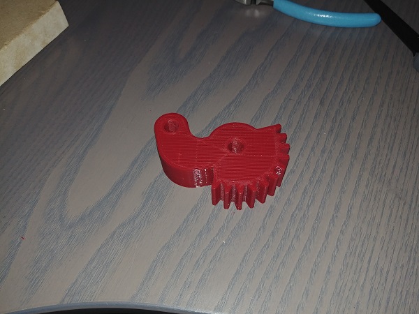
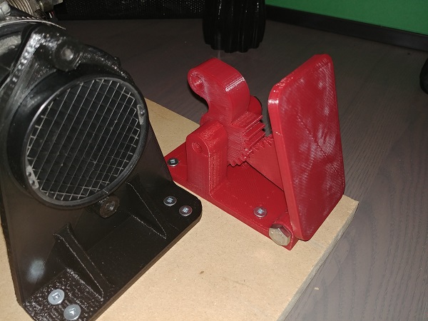

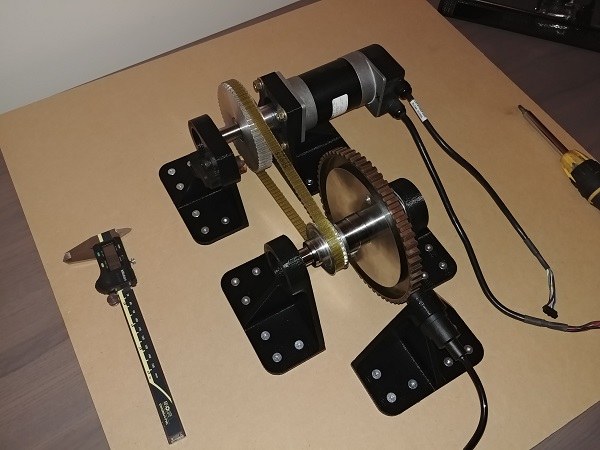
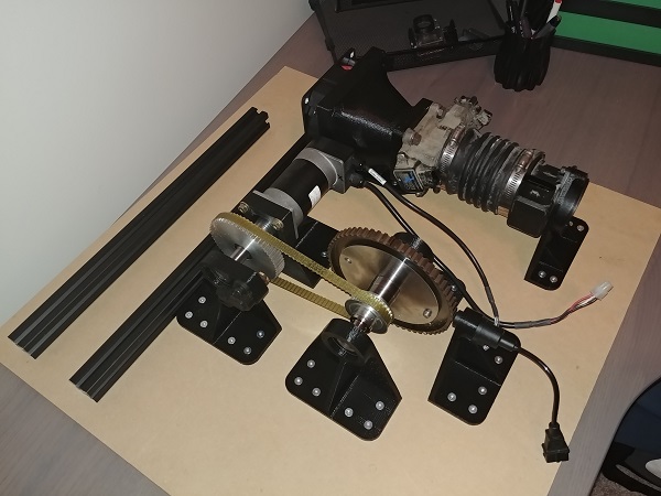
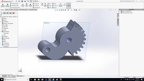
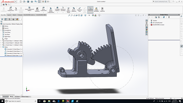
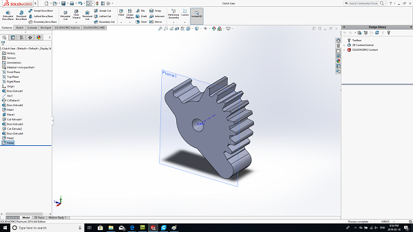
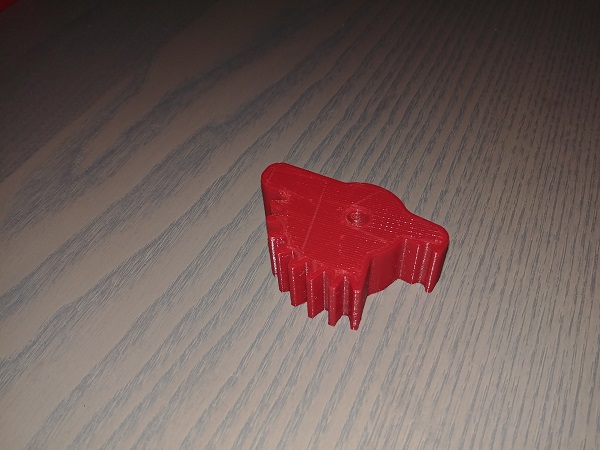
This may look quite the elaborate setup but it worked out really nice, it also avoided me having to use string. I had never designed or printed gears before, this was a worthwhile learning experience.
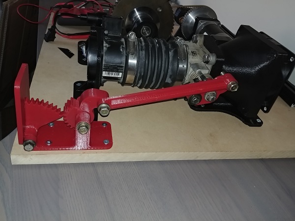
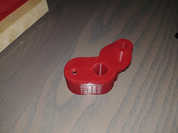
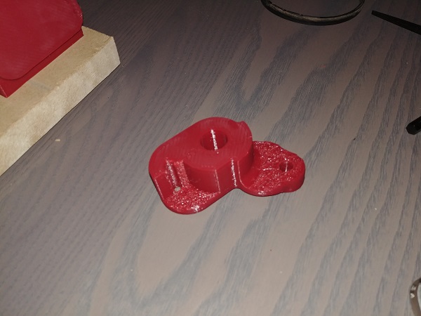
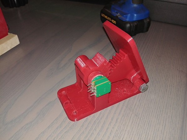
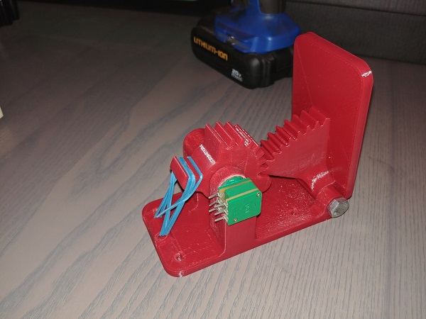
I also decided that I would need a clutch pedal since the ECU would need to know when to rev limit when changing gear. I'm not a huge fan of flat shifting but it is something I want to incorporate into my design. I will also be building a servo shifting system in the future in which it will also be required.

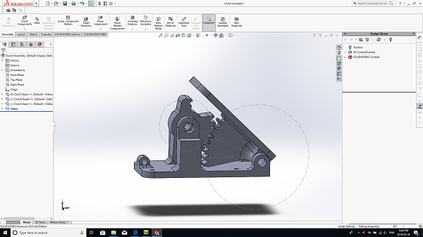
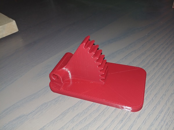
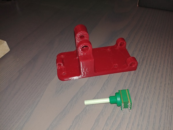
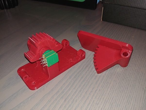
This time just a few elastic bands would suffice. A potentiometer used to determine the position of the pedal.
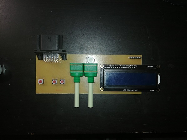
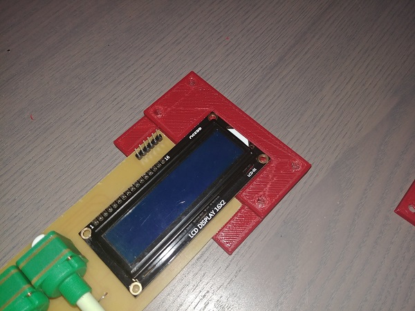
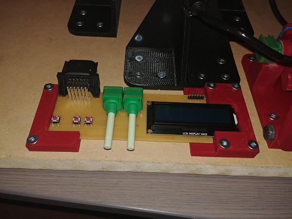
I started on a design for the user interface for the servo drive. This interface will show the crank RPM and allow the user to vary the speed manually or automatically. When running automatically the speed of the motor depends on the injector duty and the ignition timing.
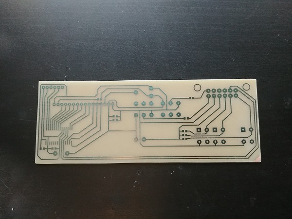
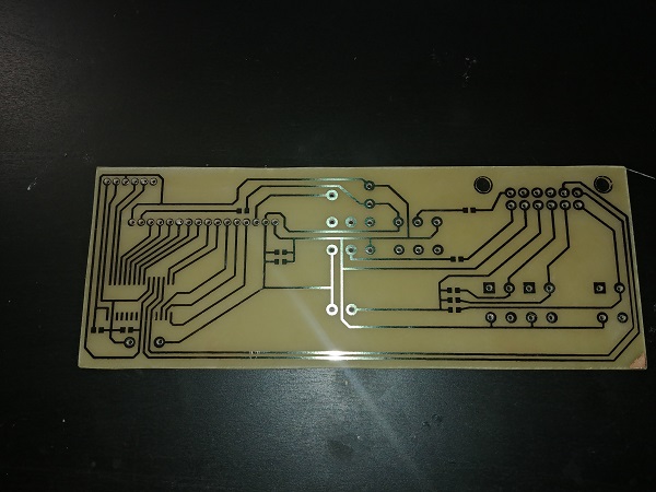
The board came out good, no flaws or issues.
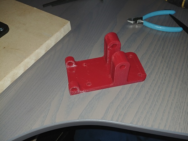
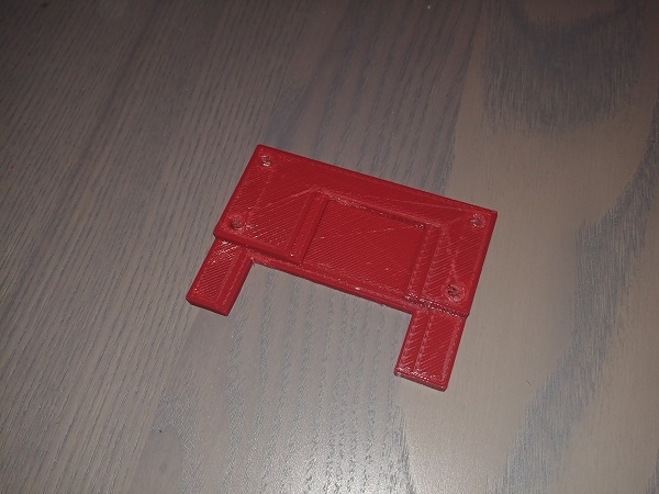
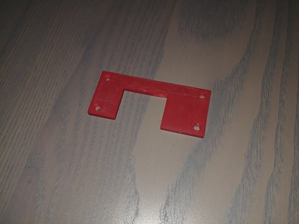
I started on a design to hold this user interface down on my rig.

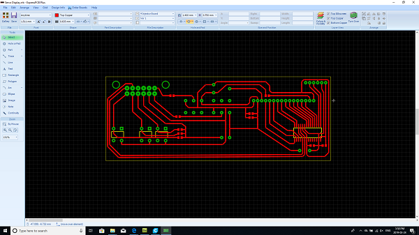
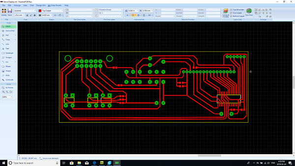

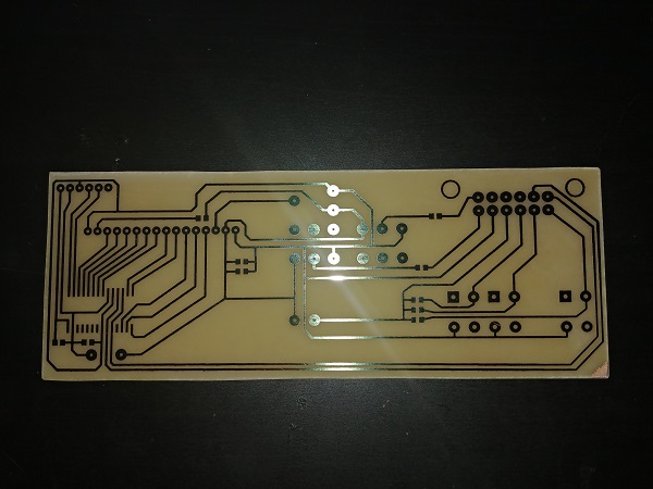
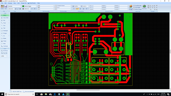
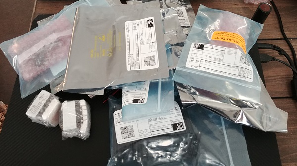
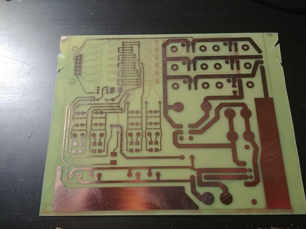
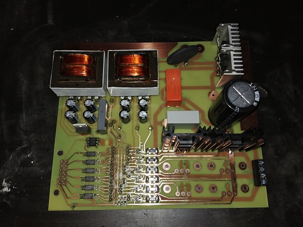
I designed the board for the servo drive and ordered some components. This board is the power side, it does not contain the control electronics which I'll build later. It is a simple 3-phase H-bridge with the latest low resistance MOSFET's meaning it should stay pretty cool. Each of the high side drivers has it's own power supply, I prefer doing this over boot-strapping supplies. A few precautions such as an NTC thermistor to limit inrush current, some large filter capacitors, an isolator relay between the supply and bridge and also some TVS diodes to protect against transient voltages.
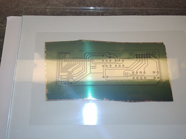
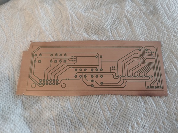
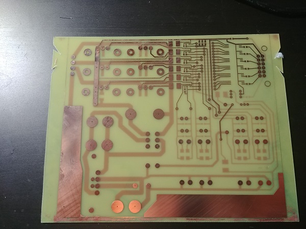
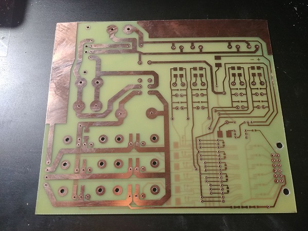
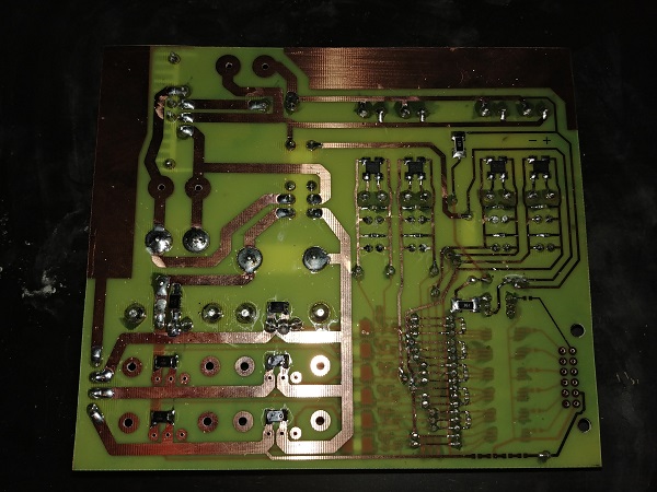
The largest double sided board I have ever etched measuring about 6 x 7.5 inches.
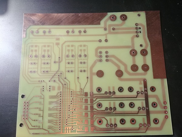
All of the holes drilled in the board.
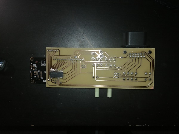
I soldered the majority of the components to the board, the only thing I forgot to order was some more connectors (12 pin bottom left). I only soldered in two of the MOSFET's on the bridge since I did not have any mounting screws and I thought it would make it awkward otherwise. The heatsinks for the bridge are fairly large and should easily dissipate the heat since the MOSFET's have a super low Rds, I imagine they would probably be ok without. The biggest if at all a concern would be the heat from the bridge rectifier as these tend to have quite large voltage drops, overall I believe this is a good design.
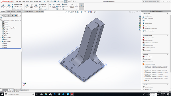
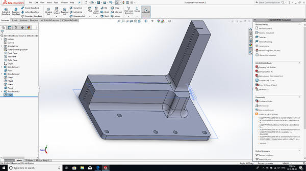
The board was originally going to be set down flat but it turned out a lot larger than I imagined. A lot of the components on this board are surface mount meaning they are very prone to failure if the board flexes at all, I would need some very sturdy board supports. I designed some mounts that would hold the board sturdily but also allow it to be removed easily.
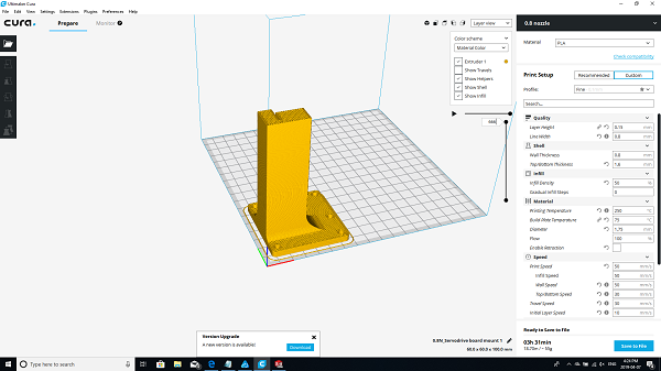
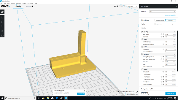
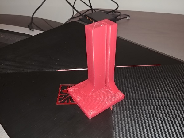
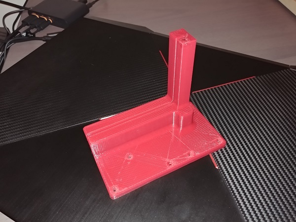
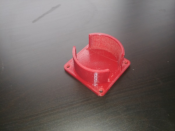
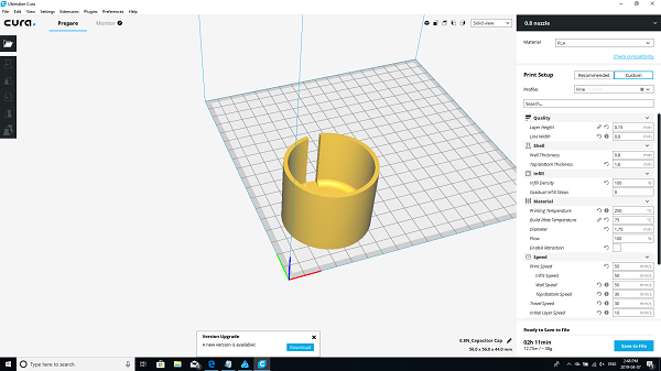
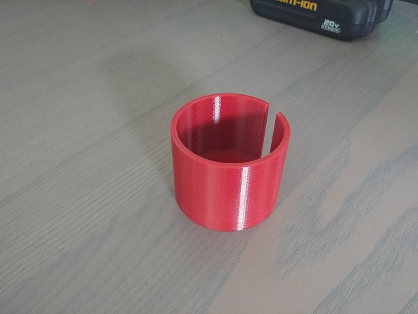
The parts were printed in PETG because it was the material in my 3D printer at the time.

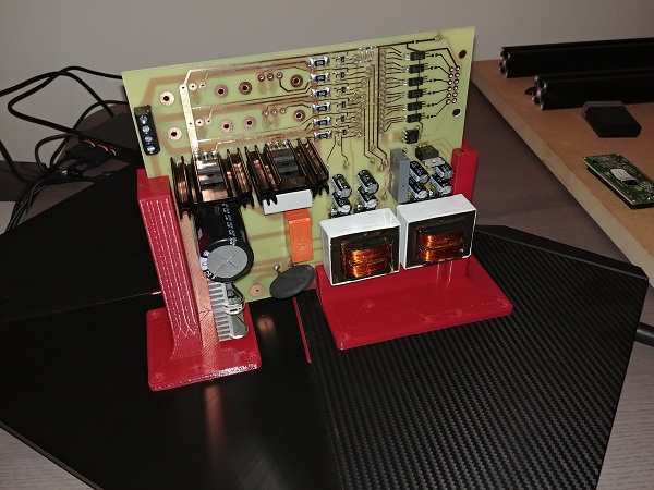
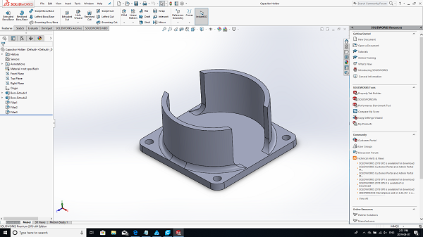
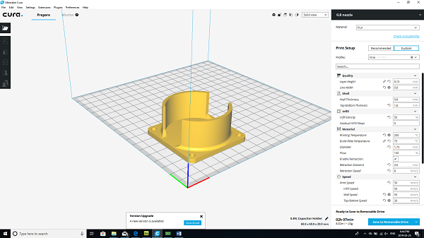
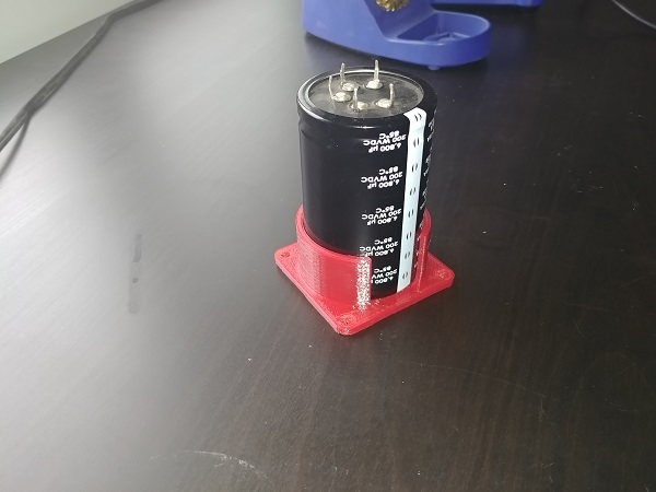
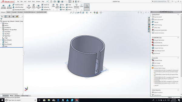
One of the filter capacitors would have to be external from the board just because it would take up so much room. I don't particularly like doing this because it adds inductance, the leads will be kept short, plus the extra filter capacitors on the board should help to avoid voltage spikes. I also chose to design a cap for the capacitor since it will be charged to around 170V, something I do not want to touch by mistake.
Overall the project is progressing nicely, please follow the link to the second page to see further advances.
Hello, if you have enjoyed reading this project, have taken an interest in another or want me to progress one further then please consider donating or even sponsoring a small amount every month, for more information on why you may like to help me out then follow the sponsor link to the left. Otherwise you can donate any amount with the link below, thank you!