Engine Simulator - Page 2
This project is about making a rig that simulates the most important sensors of an engine, it also reads injection and ignition outputs to confirm things are functioning correctly.
Follow this link to see the previous page - Page 1
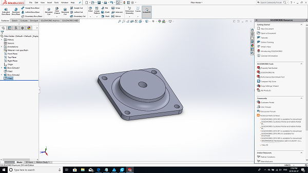
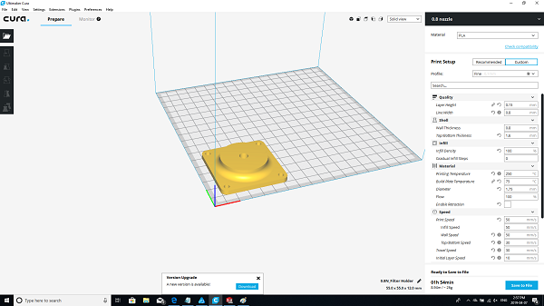
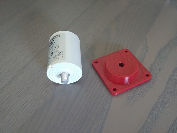
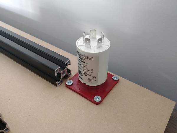
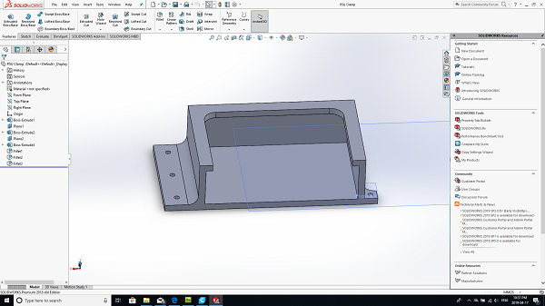
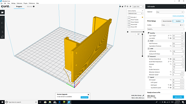
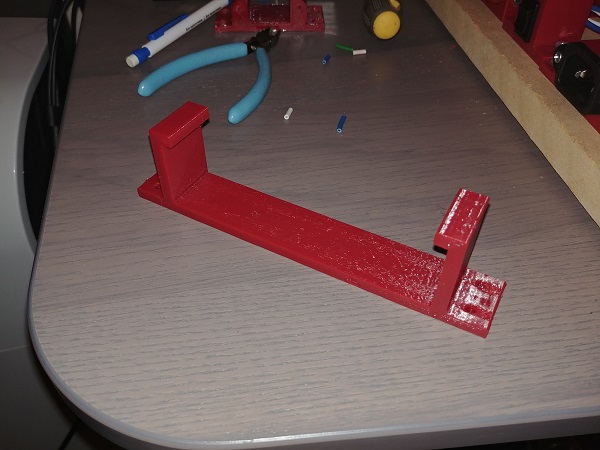
Since the servo drive will be running at a high frequency it may put some interference in the supply, likewise other appliances may also put some interference in the line supply. The most damaging parts may be high voltage transients which can cause components to fail, to combat this a filter is used. Filters are a very common aspect in any kind of supply whether it be a power supply or the drive for a motor. I designed a mount to be 3D printed for the filter to screw into.
The next step was to finish off the servo drive board, this required some connectors to be ordered along with some screws to mount the MOSFET's to the heat sinks. I worked out the values of the resistors for the feedback loop. The feedback loop reads the emf across the windings to determine whether it needs to increase switching frequency or decrease it to stay synchronised. The bus voltage will be approximately 170Vdc and the control voltage 5V. The divider reduces this voltage down to a maximum of 5V. The voltage across the windings will also be dependant of the pulse width modulation duty, the amount of time the MOSFET's are on and off. If the duty is to be on for example 50% then we can expect to see around 85V across the windings, this will also correlate to 50% of the motor speed. The drive will work as a closed-loop system in order to maintain speed via duty cycle and also synchronicity via emf.
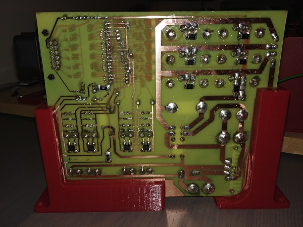
A wise tip is to remove all of the flux from the board and layer it in a conformal coating. The reason is that flux is an acidic compound, it is not the corrosive properties we have to worry about but it's ability to conduct in humid conditions. Old circuit boards were prone to failure because dust would retain moisture and the flux would allow it to conduct, something I have experienced with one of my own boards. I thoroughly wash all of my boards in solvent and detergent to remove all flux residue, I then seal it with an acrylic conformal coating. The lacquer also keeps all the traces looking bright and the board clean.
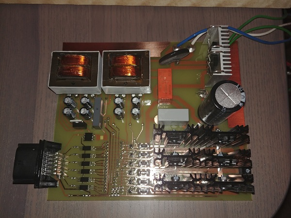
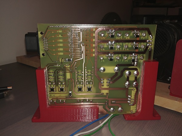
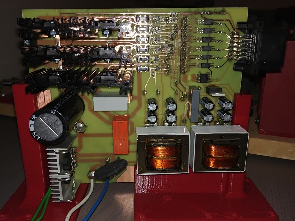
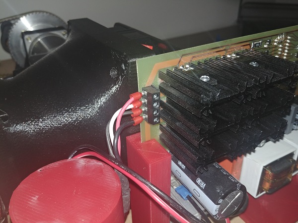
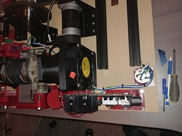
The board installed on the rig, the supply wires attached and the motor phases terminated. If flying leads have to be used like in the line wires or those for the filter capacitor then one end should always use a crimp terminal for disassembly. Soldered wires are often a weak point since the solder wicks the cores making them rigid. This is a stationary board but in something like a car the vibrations would lead to failure over time.

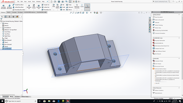
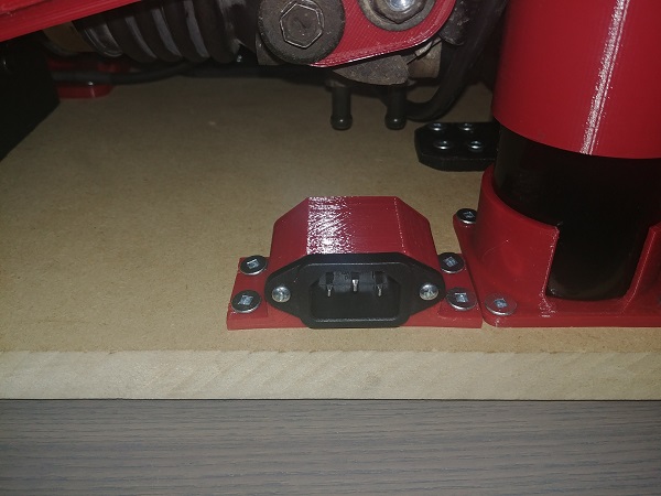
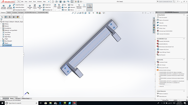
I decided I would go with a socket and lead for the supply since I don't like trailing wires if I have to transport the rig. I made sure to design the housing long enough so that the terminals would not be exposed, I do not like electrocuting myself. The reason I put the servo drive at the back was to avoid accidental electric shock, I may however go a step further and encase it in acrylic. I would probably have to install a cooling fan to stop overheating, although unlikely.
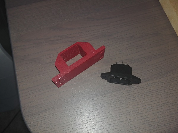
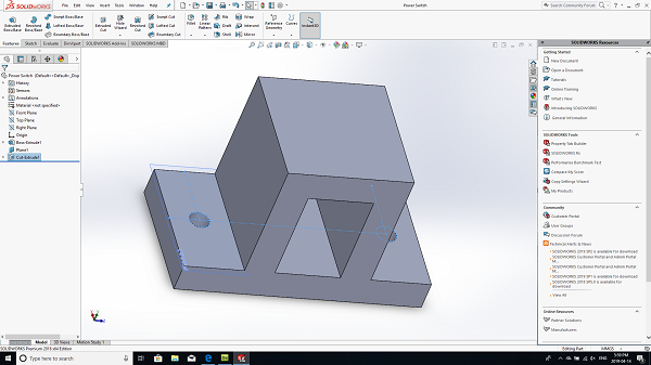
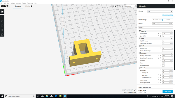
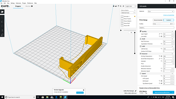
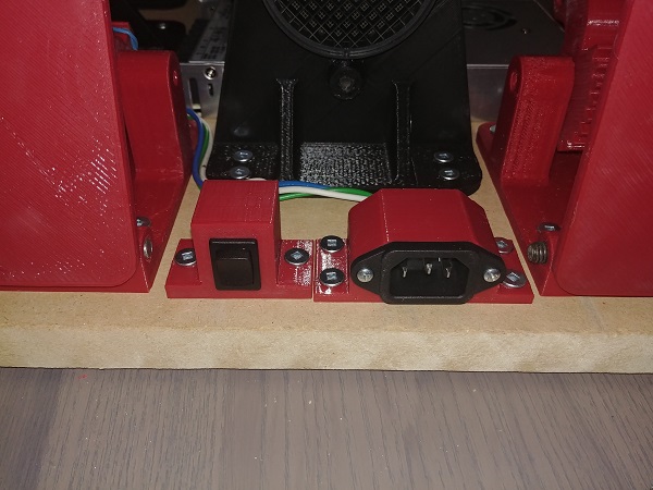
I designed a housing for the power switch, again I made it long enough as to not expose any terminals.
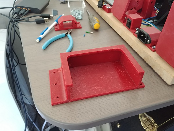
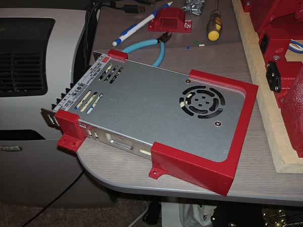
I got a power supply for the project, 12V rated at around 30A that will run everything. There weren't really any accessible mounting holes for where I wanted to place the supply, so instead I chose to 3D print some fixtures.
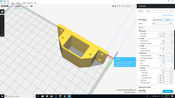
I chose to upgrade the head on my printer since I seem to get a lot of stringing, it made little difference.
I also moved the power socket and switch to the front of the rig.
I chose to wire it up, I just need to get the servo control board complete in order to run the system.
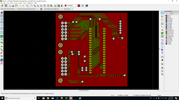
I designed a board that will send data to and from the user interface, it will also control the servo driver board. There will be one last control module that reads all of the module outputs, it will send signals to this control board telling it how fast to run the servo motor.
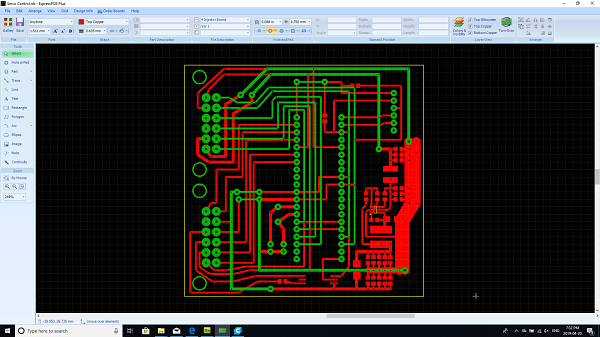
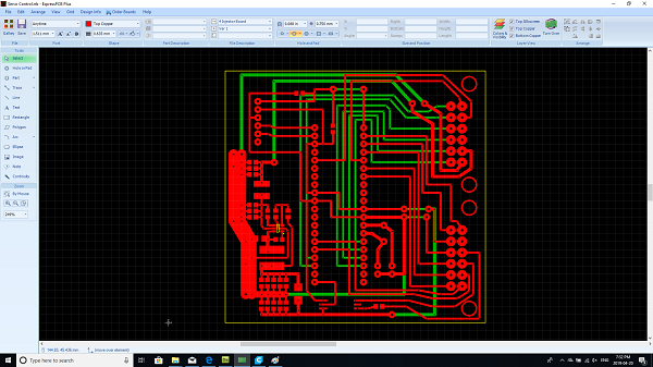
I went ahead with making the PCB only to find that my photo-resist board was defective, this has happened before. I buy the boards from a reputable manufacturer but have found them to be very inconsistent. Some boards have developed in seconds, some minutes and some have completely failed. These boards are very susceptible to light, if they are exposed by mistake then they have to be scrapped.
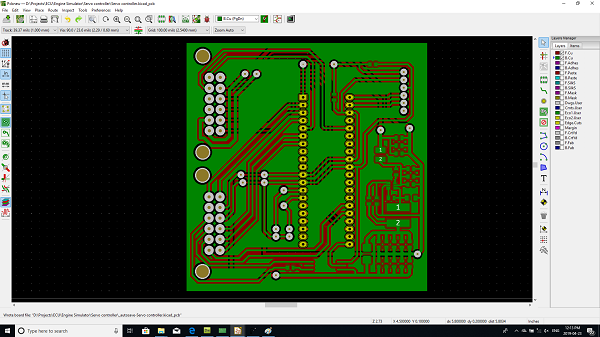
At around this time I chose to completely ditch my original methods of circuit board production and got a CNC engraver instead. So I built the control board and completely wired everything up. When I switched on the drive the NTC thermistor immediately exploded. I left this project for months thinking that I had made a programming error, so just recently I visited the project again and replaced the MOSFETS. I powered the board up this time with low voltage again to find a short, it was actually the TVS diodes that were shorted. So I think originally I must have damaged the TVS diodes through soldering heat, didn't expect them to be so sensitive.
So when the diodes were removed the control started to work, however not perfect since one of the drive chips had also blown. I decided I would start the electronics from scratch, which meant I recycled the old. I unfortunately got no pictures since it was quite a frustrating process.
So there are a couple of options, all in different price ranges, but I must get this project working very soon. I currently have an old servo drive from a CNC lathe, not sure what kind of working condition it is in, but I will try and make something from that. In a separate project I'm working on a universal IGBT / MOSFET driver that is hopefully indestructible, it's intent on being circuits that will be abused.
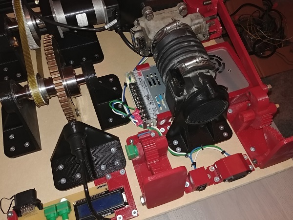
Instead I chose to skip all of this and go with a DC motor, I just didn't have the time to invest in that project. I removed all of the old electronics associated with the servo drive. My 3D printer was busy with something else so I used some scrap metal, screws and hot glue to hold the motor in place. It looks a little messy but seems to work very well. For now I will be controlling the motor from an external power supply, but eventually I will make a PWM control. The idea is that combined with spark, fueling and timing will determine the PWM of the motor and therefore the speed.

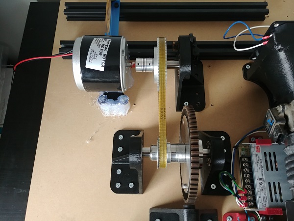
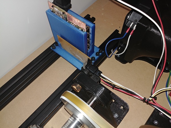
The main reason I wanted to get this thing working was to test out my timing sensor circuit board, that can be seen in the modular ECU project. I wired the VR sensor to the VR board, and also the VR board to the main control unit.
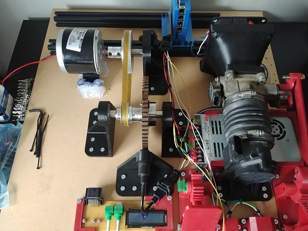
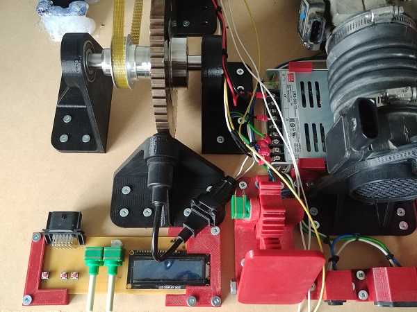
Here is a quick layout of the project so far, it is actually powered up and spinning at maybe 1000rpm. The small circuit board in the picture on the right is that which reads the VR signal and converts it to digital.

I connected my oscilloscope to the output of the board and firstly turned the sensor wheel by hand. I was quite amazed to see an output from the board since the voltage signal will be very small at this speed, so far I'm very impressed by this chip.

I switched on the motor and spun it at a reasonable speed, probably around 1000rpm cam, 2000 rpm crank. It can be seen that every "X" number of pulses there is a space, which is to be expected.

The sensor wheel is known as a 60 - 2 which means there are 60 theoretical teeth overall but two of them are missing. The signal is pulled high when passing a tooth, that means there should be 58 pulses (58 normal teeth, 2 teeth missing = 1 large space). I counted them and there are a total of 58 pulses before a space.

This is zooming even further into the missing teeth. There is a very small voltage spike on each transition which is not enough to be of any concern for the microcontroller, but I can place a snubber capacitor as a precaution.

End of Project
In another project I built up an engine so that I could test my modular ECU on it. The idea of this project was to test the Modular ECU before testing it on a live engine. I picked the timing wheel in this setup to align to that of my engine, so once happy I could test the final product on the road. I chose to sell my project car which also led to an engine swap, and the old engine broken down for parts. I learned quite a lot in the process, the main thing is that I should have gone for a much smaller engine. So this project will no longer be required. In the future I will use a small multi-cylinder air-cooled motorcycle engine to test out my ECU, I will skip this simulation setup next time.
Hello, if you have enjoyed reading this project, have taken an interest in another or want me to progress one further then please consider donating or even sponsoring a small amount every month, for more information on why you may like to help me out then follow the sponsor link to the left. Otherwise you can donate any amount with the link below, thank you!