10.8cc 2-Stroke Glow Engine - January 14/01/2016
It took me a few days to come up with a design, I thought it was about time I designed and built a project from scratch. It's a glow engine with a bore of 25mm and a stroke of 22mm making it 10.8cc. The induction of the cylinder is produced by a pressurised crankcase, the common figuration of a 2-stroke engine. I also designed this engine in the intention of it only taking a couple of days to complete, probably around three. These engines are normally run anticlockwise to stop propellers from unscrewing, I will only be running it with a flywheel but chose to run this direction. It took a total of four afternoons to complete the engine.
The crank disc was first machined from a piece of EN8, it was turned to a diameter of 37mm and the bore reamed out to 12mm. The part was cut off to a height of 10mm as further machining would be done later. The shaft itself was a piece of 12mm silver steel cut to a length of 81mm, one end was drilled and tapped to an M6 thread.
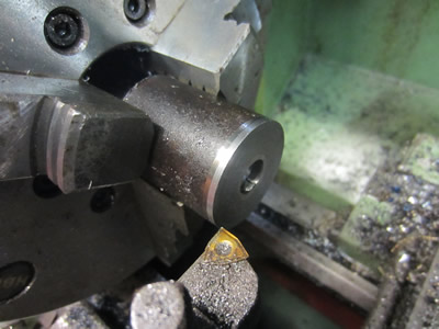
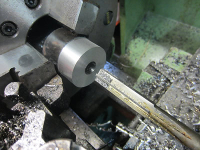
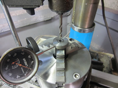
The shaft was pressed into the disc and then TIG welded in place, a further pass was taken to reduce the disc to a height of 9.5mm and the outside to a diameter of 36mm, it was TIG'ed again to ensure the weld was deep enough and then skimmed to ensure it was flat. The bore was drilled out to 8mm at a depth of 38mm, this is for the induction system. The crank was placed in a chuck inside the miller, clocked and then a hole offset by 11mm was drilled to a diameter of 6.35mm.
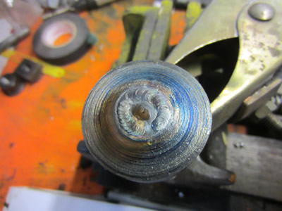
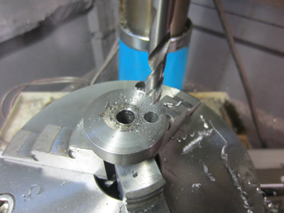
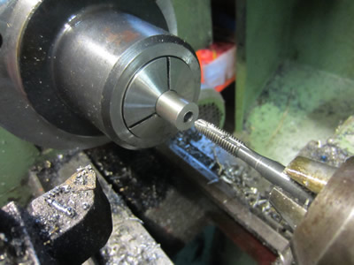
Some 8mm silver steel had a step turned on it to suit the hole I drilled earlier, it was pressed in place and the TIG welded to ensure it wouldn't come loose. The crank was placed again in a dividing head to have a slot milled across the shaft, the will act as an inlet valve for the induction system. So when the piston rises it creates a vacuum in the crankcase, this valve opens, as the piston hits top dead centre the valve closes, when the piston returns to the bottom it pressurises the crank, when the piston gets to the absolute bottom the crank gases are released into the cylinder.
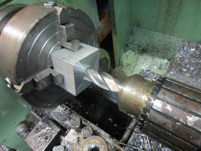
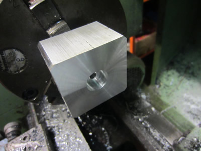
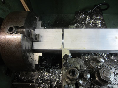
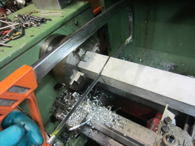
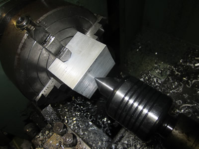
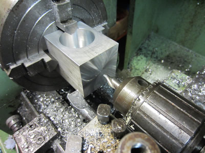
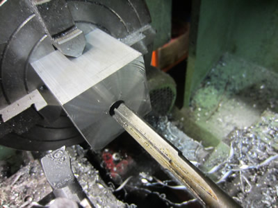
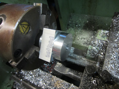
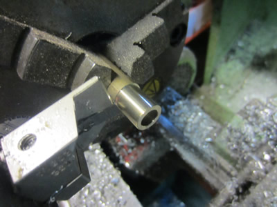
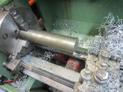
I chose to make most of the engine components from 2 inch aluminium square bar, it is a little more difficult to hold but will make the engine look a little different, clearly a homemade engine and not anything like a production run. My part off was not up to the task of cutting through the bar and decided to break, so I had the task of cutting through it manually with a hacksaw. The little piece was clocked in a 4-jaw chuck, faced and drilled through with a 5mm drill.
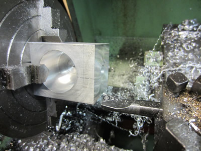
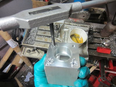
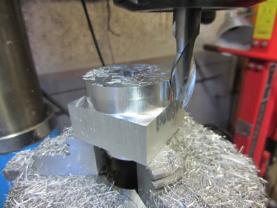
The bore was drilled out using an end mill to an approximate depth of 20mm, I then used to boring bar to finish it to 29mm at 20mm long. The face had 0.5mm taken from it to reduce the bore to a depth of 19.5mm.
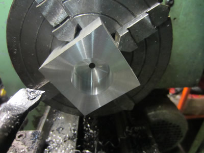
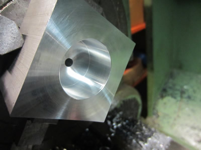
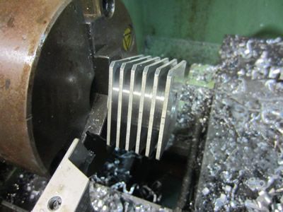
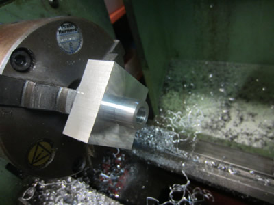
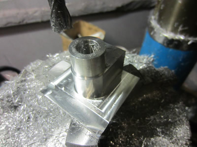
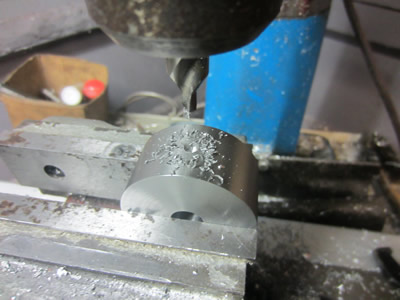
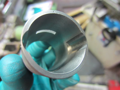
29mm was the minimum bore I could hold with my small 3-jaw chuck, so the piece of aluminium was placed back in the lathe to do the other side. The face was cut down to reduce the overall height down to 34.5mm, the outside turned slightly to chamfer the edges and the top of the cylinder recessed to accommodate the glow plug. The 5mm hole was tapped to 1/4 x 32tpi thread to suit the glowplug. My grooving tool was used to make a succession of cuts to make the cooling fins. My original design was to not have a groove at the top of the cylinder but to instead have a series of slots going across the top of the cylinder, It was in fact an error but will not affect the function of the engine, so I chose to leave it.
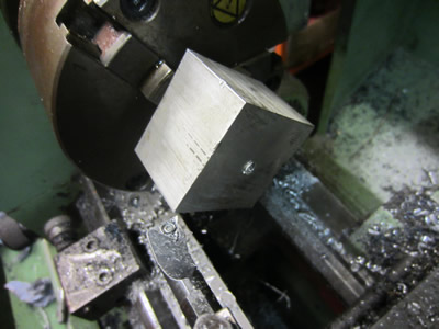
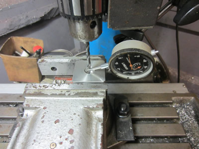
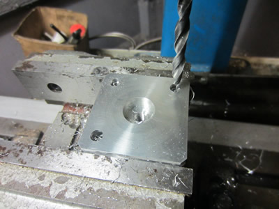
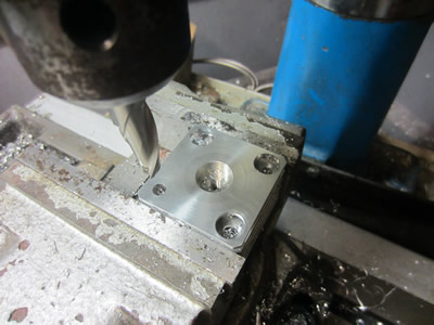
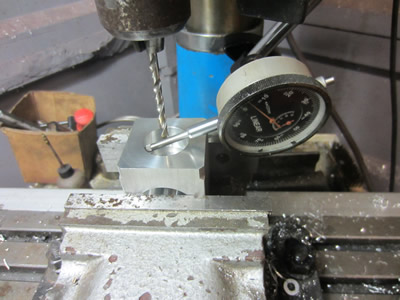
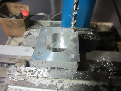
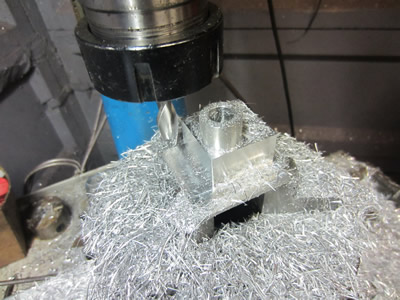
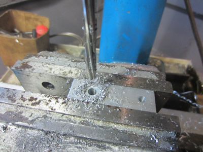
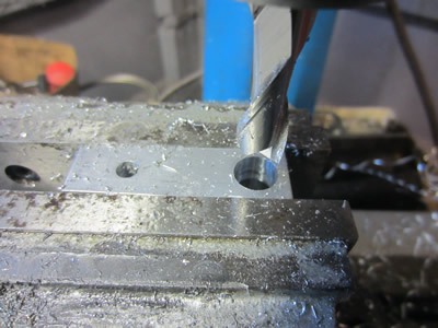
The head was placed in the miller, clocked to find its centre and then holes were drilled for the bolt holes that will hole the head down. The top fin had a further 12mm hole drilled to accept the head of the bolts, this is so they don't protrude and make the engine look unsightly.
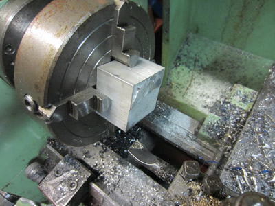
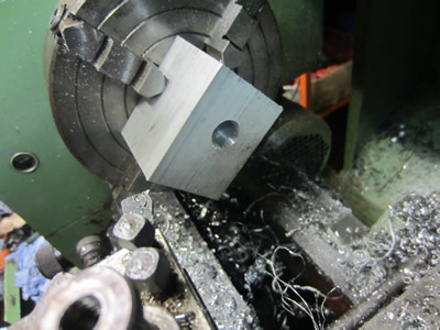
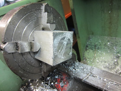
The first thing to do was cut a section of aluminium square bar, I used my grooving tool to take out some of the meat and then proceeded with using the hacksaw. The cut off side was faced flat, the section was cut to a height of 64mm to allow for some surpluss material to be cut.
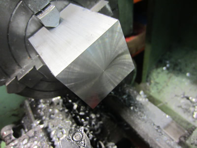
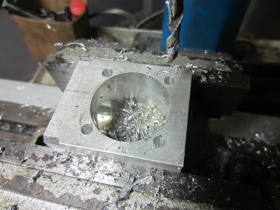
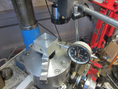
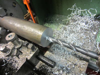
The block was placed on it's side in the chuck to bore out the hole for the crank bearing. It was drilled and then bored out to an exact diameter of 38mm to a depth of at least 31mm, I think it came out about 31.2mm.
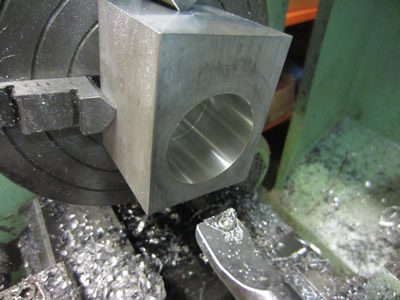
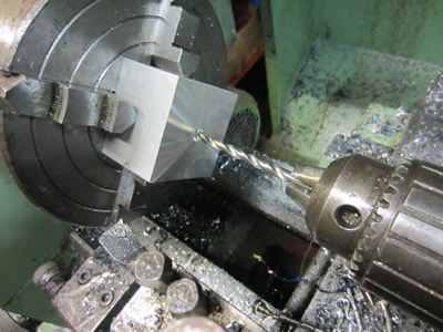
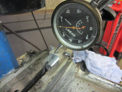
The block was then placed in length ways to bore the hole for the cylinder liner. The reason for doing it this way round is so that I could easily measure the distance from the centre of the crank bore to the top of the crankcase, this all ensures that the timing of the ports will be correct.
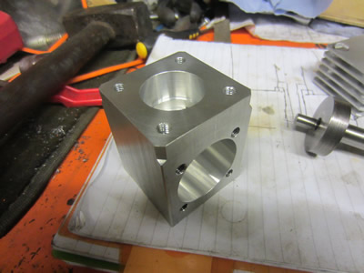
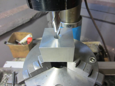
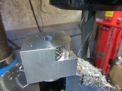
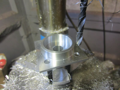
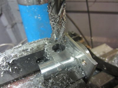
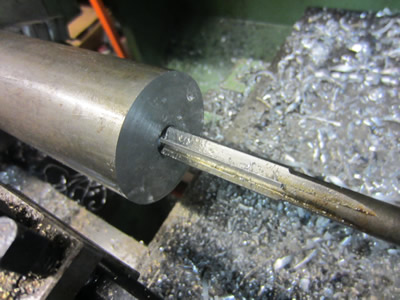
The bore was cut out to exactly 29mm at a length of 16mm, the remaining aluminium was bored out to 26mm deep, enough so there were no major steps in the case itself. The case was placed upright in the miller and clocked central, a series of holes were drilled, these will hold the bolts that fix the head to the case.

The threads were tapped to M6. The case was placed on it's side to drill the holes for the bolts that hold the crank bearing to the case, these holes were again tapped to M6. The case is now complete, I chose not to drill the backing bolt holes as I will probably only run the engine in a vice.
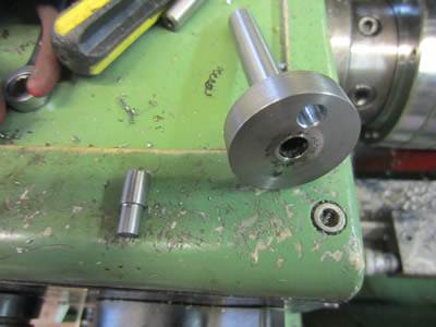
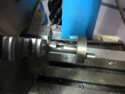
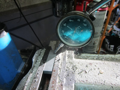
Another piece of aluminium was cut to size, drilled out and reamed to the exact diameter of 12mm. An internal step was turned to hold a bearing and an outside step turned to suit the crank case. All of these parts were machined to fit the other parts with a clearance of only 0.01mm to ensure everything fit perfect, or an interference of 0.01mm for the bearing.

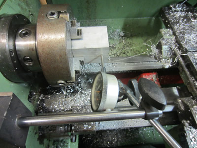
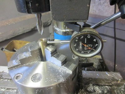
The crank bearing was placed upside down in the rotary vice to machine most of the meat away. The piece was clocked square and central to ensure that everything would look inline, not that it would matter too much if it wasn't.
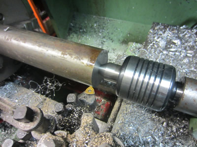
I was using the miller to machine the back of it round to try and avoid using the lathe, but overall it took way too long in the miller. So I placed it in the lathe to turn the rest of it down to a round section measuring 20mm diameter at a length of 14mm, once this was complete it was clocked true in the miller again.
The profile took quite a considerable amount of time to complete but overall it came out to an excellent finish. The only problem with milling is that there are a lot of direction marks left, which look major but can only be felt with the nail, a final finishing process at the end of the construction will remove all of these machining marks. The bearing was placed the other way around in the chuck, clocked square and then a series of holes were drilled that will allow the bolts to fit through in order to fix the bearing assembly to the crank case.
The vice was placed back in the miller and the bearing assembly clocked flat, using a dowell I referenced the readouts and drilled a hole through the top. The bearing was placed on its side to drill the hole for the carb butterfly, it originally should have been 12mm but the slot drill decided to resonate so I had to drill it out to 14mm to improve the finish.
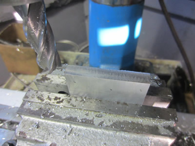
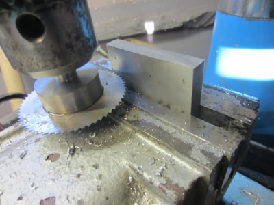
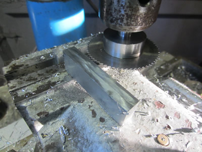
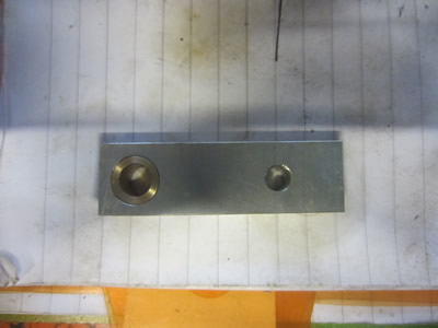
I really wanted to make the conrod out of 7075 aluminium which is a high strength alloy but I couldn't source any the right size. I instead general engineering alloy 6082 and went for bronze bushes to reduce wear. The engine won't be operating at high powers so there should be no concern of the conrod failing. Firstly I cut a section of aluminium from 10mm plate making it 17mm wide, these slitting saws really come in handy.
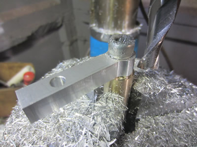
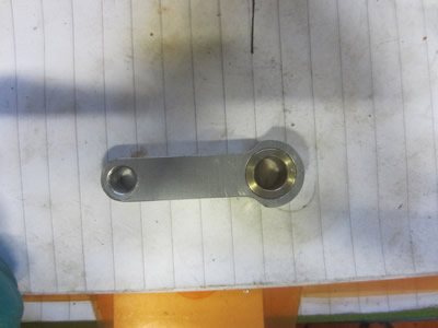
The section of aluminium was clocked flat in the vice and then two holes were drilled at 5mm, both spaced 35mm apart. One hole was reamed to 6mm and then other hole was bored out to 12mm with a slot drill.
A bush was made from phosphor bronze, it's bore reamed out too 8mm and then outside turned 0.01mm larger than the 12mm hole in the conrod, this was to provide an interference fit.
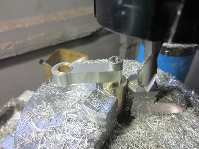
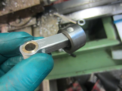
A piece of brass was turned in the lathe and then an M8 thread tapped inside of it, the bar was placed in the dividing head, a bolt pushed through the conrod and tightened. I was a little bit nervous milling out the contour of the conrod but it seemed to come out ok in the end.
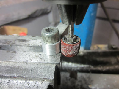
The big end of the conrod should have measured 14mm but I did the dimensions in my head and managed to make it 16mm instead which left no clearance in the crankcase. I put a sanding wheel in the miller and sanded down the contour by rotating it by hand, I took it down to the 14mm which it should be.
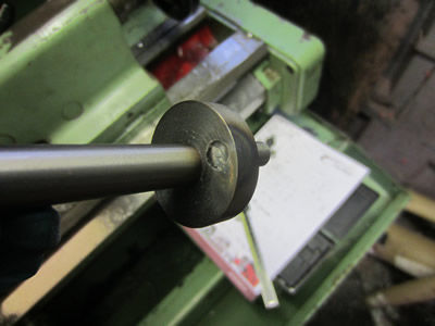
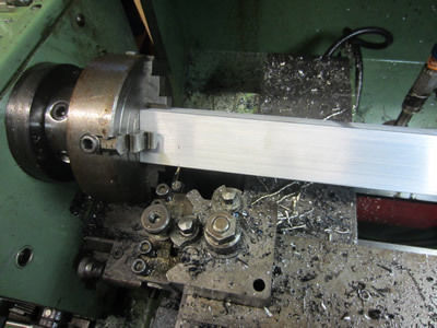
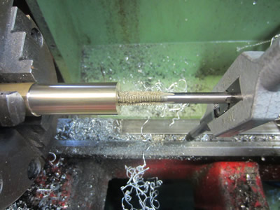
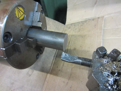
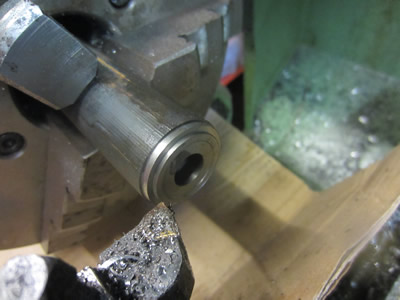
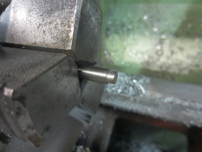
The material of choice was mild steel and my piece of bar was 400mm long which I wasn't prepared to cut down with a hacksaw. The overhang was about 250mm but the bar faced off fine, so I drilled and reamed out the bore to 12mm to match the crankshaft.
A live centre was used to keep the bar from deflecting, the outside was finished to 50mm at a feed of 0.1 at 1000rpm, it came out really nice.
The flywheel was almost parted off with the grooving tool and then cut off with a hacksaw, this ensured there were no mishaps. The other side was faced flat making sure that the height of the flywheel was exactly 25mm. The wheel was placed in the miller to have two holes drilled and tapped to M6, a grubscrew will secure it to the crankshaft.
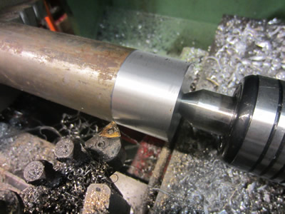
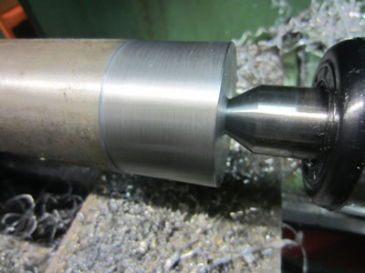
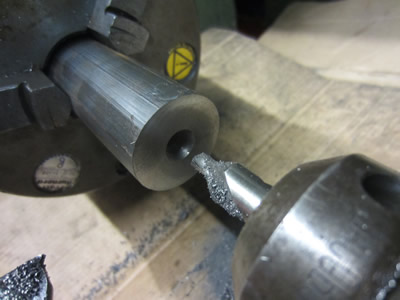
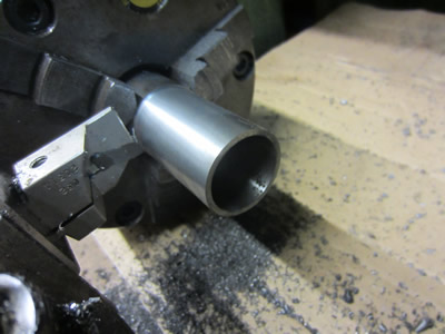
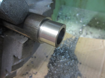
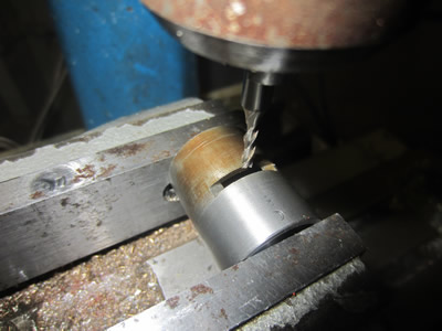
There are many combinations for cylinder and piston material. I chose to go with cast iron as it is the best material of choice, it machines nicely, leaves no burrs, an excellent finish can be achieved and it holds oil on it's surface. My main reason is that when it comes to machining the ports no burrs will be produced making it an easier process. The chuck I used was no good for bar as it only held on the back of the jaws, I did however manage to make do by over tightening the chuck. The bar was drilled out and bored first to try and retain some rigidity to ensure a decent finish.
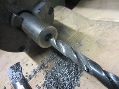
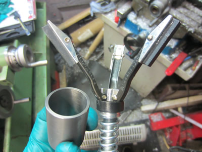
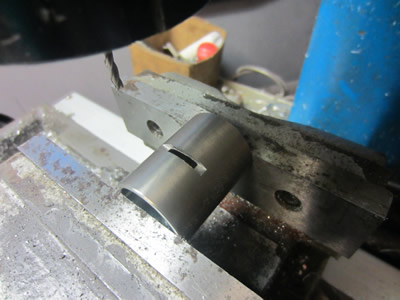
The cylinder was parted off and then honed in a cup of oily water to increase the surface finish. The liner was placed in a chuck in the miller and clocked to find the centre.
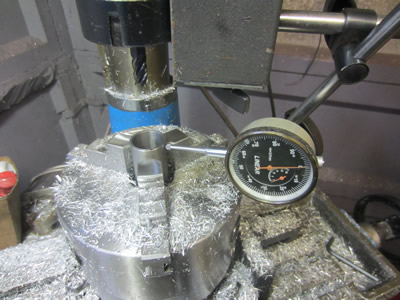
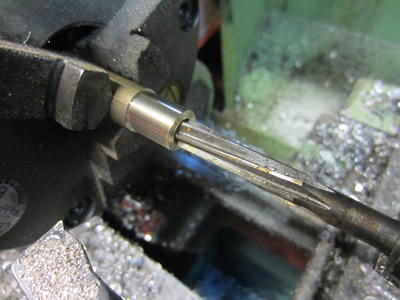
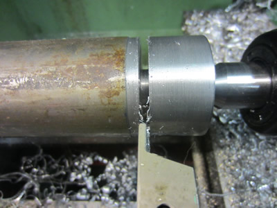
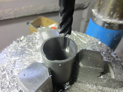
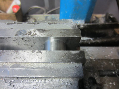
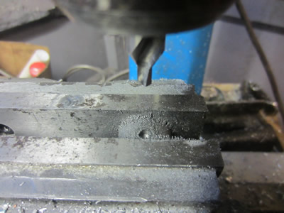
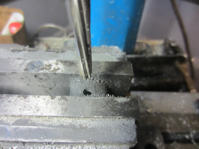
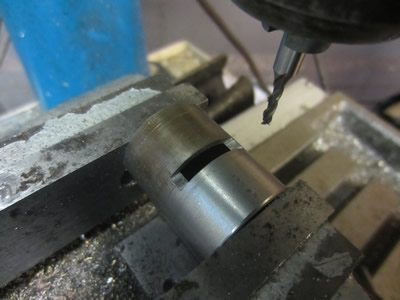
Using a carbide end mill I cut the induction port to a depth of 16.5mm, a depth of 1.5mm into the wall. The cylinder was placed length ways in the vice and then a slot milled at a depth of 4mm at a width of 3mm, it was turned around to mill another slot . This means that overall there are two induction and two exhaust ports all of which are equally spaced from one another. No deburring had to be done due to the brittle nature of cast iron.
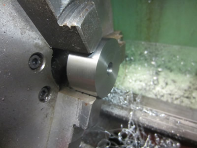
I was a little unsure what material to make the piston out of but found out that the carbon steel that I was going to use measured same as what the finished piston size would be, so I could not finish it properly. I chose to go for cast iron instead, the engine will not have a very long working life but should bed in quickly and be relatively straight forward. The bar was faced, drilled and then bored out to a diameter of 18mm at 12mm deep.

The piston was turned to 25.01mm and sanded smooth to fit the cylinder liner, ensuring a tight fit. The piston was placed in the miller to have a 5mm hole drilled through both side.
One of the holes was reamed to 6mm. I pin was then made out of silver steel which had an interference fit made on it for the 5mm end. The pin was pushed through the piston and conrod before being pressed in place.
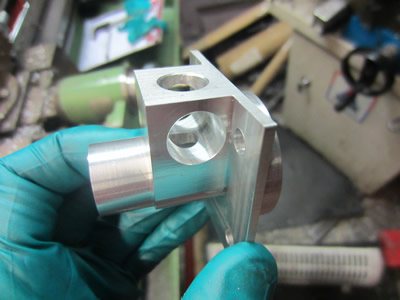
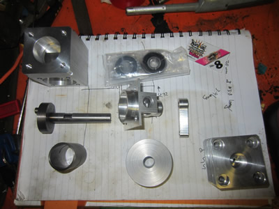
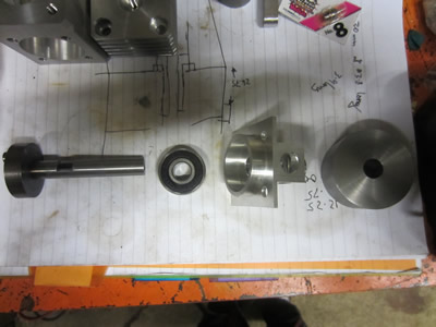
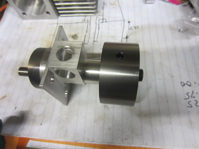
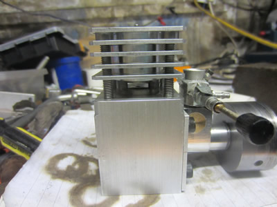
The first picture shows all of the completed parts, apart from the piston and the carb butterfly. The ball bearing was pressed into the crank bearing case and then the crankshaft itself pushed through the lot. The flywheel was held in place by the aid of a couple of grubscrews, the shaft did have some dimples drilled into it to ensure the grubscrews would act like a key. There is also a bolt screwed into the end of the shaft that will be used to start the engine, due to it running anticlockwise it meant that this screw also had to be keyed in place with a grubscrew. The grubscrew holding the bolt in place passes through a hole in the crankshaft, it was not shown in the pictures earlier but is in the design.
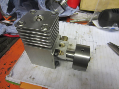
The crank placed into the case along with the conrod and piston assembly, the cylinder liner pushed into the crankcase over the top of the piston and then the head bolted on the top of this. I first made sure that the engine turned over freely and then inserted the glow plug and the carb butterfly, just a quick one I made up to get it running. I could get the engine to fire but could not get it to sustain running which was due to the carb, I didn't have the right tools to thread a fuel needle. I chose to buy a cheap RC engine and use the carb off that, the engine will also be used in another project. A few days later I fit the carb to the engine, I could still get it to fire but not to run, I feared this could be a problem with the piston and the porting which I would have to modify. The first thing I tried was inserting a 3mm spacer ring below the liner to raise the induction ports and increase flow into the combustion chamber, 3mm was also shaved off the top of the liner and 3mm from the bottom of the head. The engine started up immediately but only ran for a few seconds, I think the exhaust gases are pushing the induction gases back into the crank case.
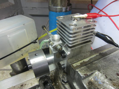
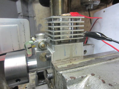
I suspected that the exhaust ports were too small and the gases where pushing the fuel back into the crank case. I removed the liner, placed it in the miller again and extended the ports from 3mm to 4.5mm long and the depth from 4 to 5mm. The engine instanly fired up and reved pretty high, I'm guessing around 10,000rpm due to the sound it made.
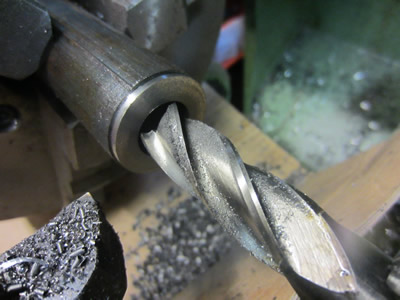
I did hope to make a video of the engine running but when I started recording and tried to start the engine I managed to break the bolt that is used to start it, this is the second time. I placed the crank back in the lathe to drill out the bolt and make a bigger thread, the drill however snapped when I broke through the bolt, great. When I manage to remove the drill I will hopefully post a video of it running soon.
Hello, if you have enjoyed reading this project, have taken an interest in another or want me to progress one further then please consider donating or even sponsoring a small amount every month, for more information on why you may like to help me out then follow the sponsor link to the left. Otherwise you can donate any amount with the link below, thank you!