IGBT and MOSFET Desaturation Protection
When an IGBT or MOSFET are fully "on" they are known to be saturated, when they exceed their maximum current ratings they are known to "over saturate" which will eventually cause failure of the device. While IGBT's and MOSFET's are used for very similar applications it should be noted there are two main differences, the MOSFET tends to lean towards high frequency low-power switching whereas the IGBT leans towards lower frequency and harsher switching conditions, these are just the common assumptions. Due to the fairly ruggedised features of the IGBT they normally have around a 10us short-circuit capability and a higher voltage rating which makes them a lot easier to protect. The MOSFET particularly due to their lower current density cannot handle short-circuit for very long, probably only around 1us.
It tends to be a fact that the MOSFET's switch a constant load or a predictable load such as a transformer, normally in something like a switch mode power supply. It is fairly uncommon for such devices like these to even have over-saturation protection, yes they do have current limiting devices, but desaturation is normally only required on a short, so if a MOSFET is driving a transformer and a short occurs then it's likely that the transformer has failed, the device is normally replaced, for example a laptop charger. The IGBT is used in applications such as motor drives and inverters, where an external short will directly affect the IGBT's. So firstly I'm going to discuss IGBT's and then do some testing, later I will discuss and test MOSFET's.
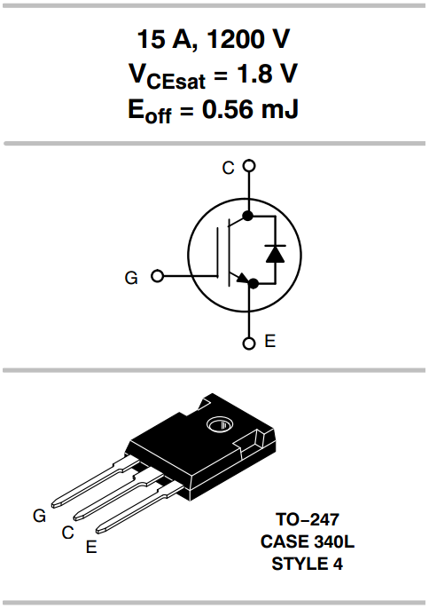
Firstly l will choose an IGBT such as the NGTB15N120IHLWG, particularly due to that I have some to test. It has a saturation voltage of 1.8V at 15A. Note that in the datasheets these are the maximum ratings at their maximum temperature, this IGBT can infact run at 30A at low temperature. Eoff are the switching losses, these losses are dissipated as heat so it must be taken into consideration with the operating frequency.
So what is saturation voltage (Vcesat), it is the voltage drop across the component just like if it were to be a diode. As you know a voltage drop is dissipated energy as it indicates a resistance, so imagine running at 15A it would dissipate an energy of 27W, a total dissipation of 62.5W is possible meaning the rest could be used for switching losses or driving a slightly higher current.
Now imagine if you were to exceed the current you would infact be increasing the amount of power to be dissipated, exceeding this 62.5W would cause component failure. There are two temperatures you will see on a datasheet, one is the junction temperature (Tj) and the case temperature (Tc). The junction is the semiconductor part and the case is were you bolt the heatsink to. The junction is secured to the case and cooled via conduction, now since these are not perfect conductors there is a limit to the amount of power the case can draw from the junction, likewise there is a maximum amount of power the heatsink can draw from the case.
When you put current across an IGBT you get a voltage drop, this drop actually increases exponentially as the current does. So an extra amp over the rating could equate to an extra 2W, then an extra amp on top could be 5W, it wouldn't be long before the maximum power dissipation would be exceeded.
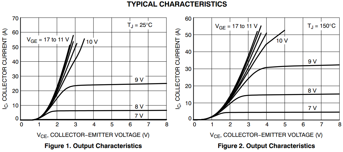
Another thing to note is the gate voltage, what turns the IGBT on or off. As gate voltage increases the so does the current capability, now that should seem quite obvious, there will be minimum voltage for the IGBT to turn of minus the voltage drop, if the voltage drop increases then the IGBT won't be able to turn on effectively any more leading to power losses, remember the power is lost through transition.
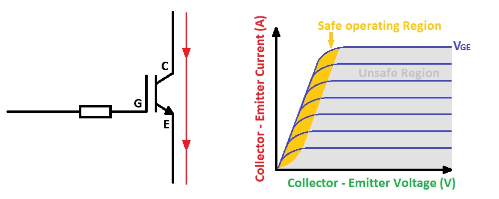
The following diagram shows what I mean, the safe operating region is where over-saturation starts to occur, as you can see the collector-emitter voltage starts to run away with current. The collecter-emitter voltage when the IGBT is on is known as the saturation voltage. This graph is the type of thing you want to be looking for in a datasheet as it will tell you the safe operating current with respect to the gate voltage, normally you will run gates at 15V which is normally the last or second to last plot.
It is quite common to get a few of these graphs in a datasheet, normal one at Tc 25°C and one at Tc 125°C. This datasheet is very unusual as it's dealing with the junction temperatures, it only means that I'll have to work out the conduction between the junction and the case.
Now an IGBT is not a perfect conductor and has resistance so will have a limitation to the short-circuit current that can go through it, albeit for a very short time. The great thing with IGBT's is that they can infact deal with a short-circuit for between 4 and 10us, most IGBT's now can deal with up to 10us, such as the one in the datasheet, it is normally stated. It's quite difficult to get an idea of the kind of current you will see across an IGBT in short circuit as the graph isn't linear, but if I was to take two points from the graph I would assume an IGBT such as this would reach 12kA with a saturation of 1200V, now that would be almost impossible because that would mean no inductance, this would be an instantaneous current. Going on that value would get 14MW across the IGBT, now since 62.5W dissipation is possible, or 62.5 Joules / second then, 62.5 / 14M would get us a maximum time of 4us. Now considering there will be inductance to deal with this doesn't sound that far off the mark, this is 4us short time per second, these calculations should not be used in design considerations. The current will however be much lower, probably around 1kA. This is just to show that it is more useful to do testing than predictions from a datasheet because it's not all that obvious what currents will be dealt with.
Since we know nearly all IGBT's can handle a short-circuit time of 10us then we know how much time we have to turn the IGBT off safely. It should also be noted that due to there being a high current present and with the inductance in the wires if I was to turn the IGBT off fast then there would be a huge voltage transient, IGBT's are good with current but not so with an over-voltage. An over-voltage situation will cause an avalanche to occur, this will be explained later but IGBT's are avalanche rated. The IGBT is normally turned off gradually in around 5 to 10us, remember that the less gate voltage there is the less current the IGBT can take. So ideally an IGBT driver would drop the voltage linearly to zero, this is quite difficult to achieve with all IGBT's so normally the voltage is dropped to around 8 or 9V and then to 0V over the 5us margin (8 to 9V is the voltage where the IGBT turns off).
There needs to be a way to detect the amount of current across the IGBT, there are two ways of doing this, use a current sensing resistor or measure the voltage drop across the IGBT. Using current sensing resistors are quite an accurate method and mostly used for current regulation, they are quite commonly used. Otherwise the voltage across the IGBT is measured as with any IGBT you will know if an over-current situation has occurred when the saturation voltage has been exceeded. Normally when the saturation voltage has reached between 5 and 9V the driver will turn off the IGBT. Both of these methods can be used in conjunction with each other, one for IGBT protection and the other for load regulation.
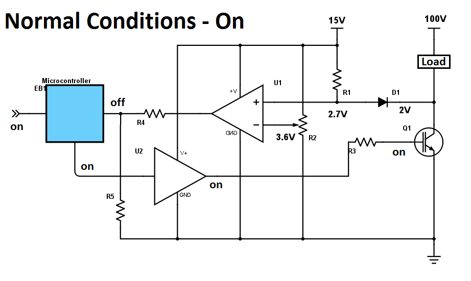
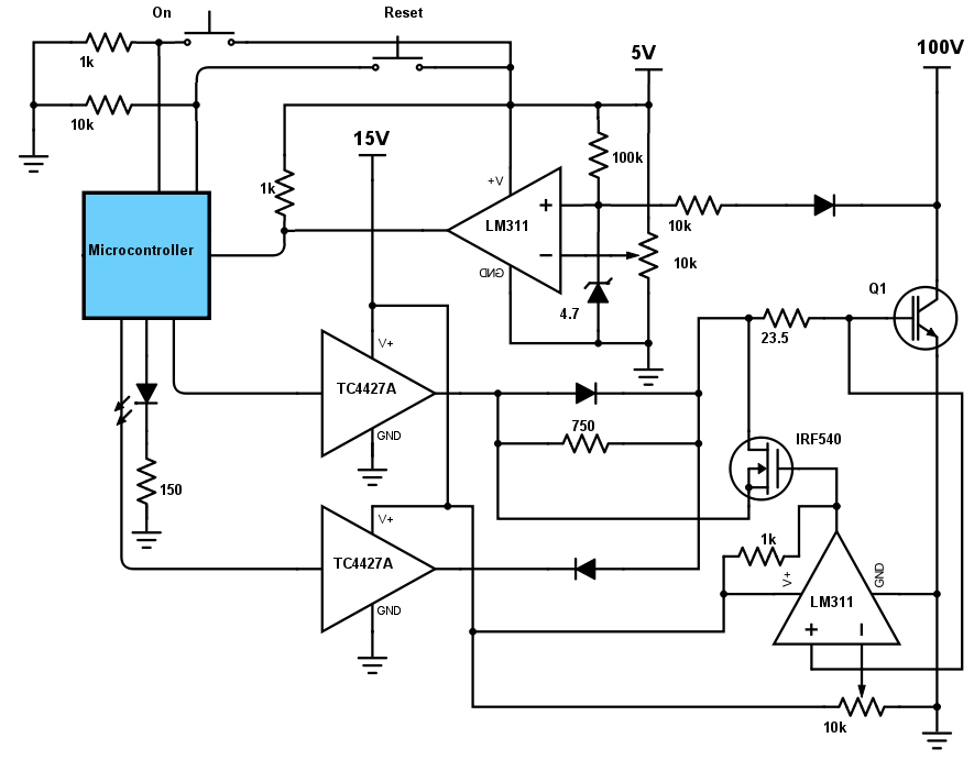
There are plenty of drivers out there that will do this job, I'd rather build one. I also want to demonstrate the difference between a "hard" turn off, a "stepped" turn off and a "soft" turn off. The longer it takes to turn an IGBT off the more energy will be dissipated. Below is the basic circuit for the IGBT control with desaturation protection, using a microcontroller is a lot more concise than using logic circuits. As you can see when the IGBT is off there will be 100V across it, there is a diode used for detection, one side has a 15V source, the other 100V, therefore no current flows. The comparator compares to the reference set at 3.6V and sets the output high, the microcontroller ignores this scenario.
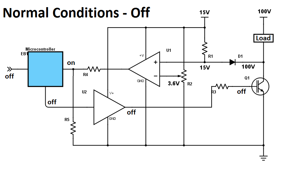
An input is sent to the microcontroller telling it to turn on the IGBT, it does, the voltage across the IGBT is now only 2V. Originally there was 15V before the diode but now because there is only 2V after it a current will flow, due to the voltage drop of 0.7V, the diode will have 2.7V before it. The voltage is lower than the reference and therefore the comparators output remains low, the microcontroller ignores it.
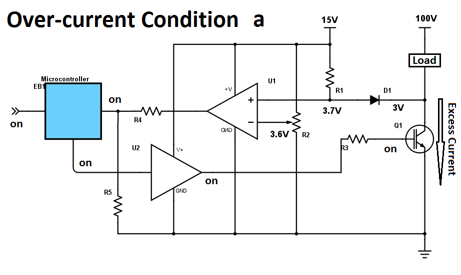
Now for some reason there is a short circuit and an excessive amount of current flows causing the saturation voltage across the IGBT to increase to 3V. The voltage before the diode has now risen to 3.7V, the voltage is above the reference and the comparator output now becomes high, this indicates to the chip that over-current has occurred.
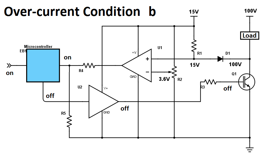
The chip recognises this and turns off the IGBT, now the voltage will rise across the IGBT due to it being off, the comparator is still indicating over-current. The chip knows this and will not turn the IGBT back on again until the signal input has been turned off. Even when the signal has been turned off the comparator is still indicating that the over-current situation is present when infact no current is passing through the IGBT. The microcontroller knows this and will still turn on the IGBT, there will be a pause to allow the IGBT to fully turn on and then it will read the input for over-current. Since the IGBT has been allowed time to turn on and there is no fault current the comparator will be off as the saturation voltage will only be 2V. Using a microcontroller is a lot easier to use as the delays can be precisely programmed and so can the logic instead of using multiple chips. Even the slowest IGBT's will take at most 1us to turn on so if there was still a short fault then there still would be plenty of time to shut down the IGBT safely.
It is recommended that a circuit such as this will shut down the drivers until reset, there is no point switching back on the IGBT if a fault is still present, this would almost certainly cause component failure due to heating. My circuit will be based on the above, I will be using some resistors as a load and shorting these for the over-current situation. My supply is capable of 15A but has two massive filter capacitors so these should provide the hundreds of amps in the case of a short, remember most inverters and motors drivers will have large filter capacitors too. Another thing to consider is the desaturation detection voltage, while an IGBT is over-saturating above 2V it is quite common to set the detection voltage at 7V. A motor drive may have a few current spikes leaning the IGBT to over-saturate, setting the detection voltage low could cause detection to occur even when the current spike may not be a short, personally an IGBT should never be running on it's limits in any application and there should be a large safety margin, I personally believe that 1V over the saturation voltage is required. Another reason for setting it so high is so the desaturation detection doesn't interfere with the current measuring circuit as this will reduce the IGBT's duty cycle instead of turning them off.
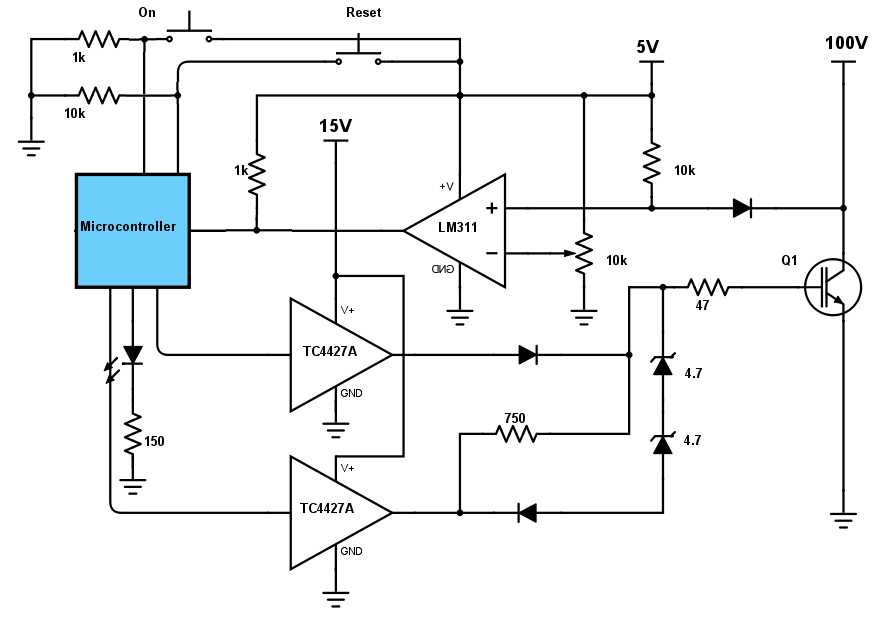
There are a few tests that I will be showing; a hard turn off, a soft turn off and a two-stage turn off. The voltage spikes across the IGBT will be measured along with the voltage spikes at the IGBT gate, reducing voltage spikes will help prevent damage or the IGBT avalanching. Below is my rendition of the above circuit, I have used the IGBT that I mentioned earlier along with a 16F628A microcontroller to do the work. There are five pins used total, the input, the output, a reset, an over-current indicator which goes to an LED and also a clamp output. The schematic is a little more detailed than the above as I have included the two-step soft turn off method.
As you can see the circuit is not intended for normal operations, all we are doing is checking the turn-off period of the IGBT and not the turn-on.
The first test is simply on and off with just a single gate resistor between the driver and the IGBT.
The second test is the addition of the 750 ohm resistor between the gate and the off-driver.
The third test is the addition of zener diodes to quickly drop the voltage, the 750 ohm resistor drops the residual voltage at the IGBT gate.
Here is the circuit built onto a breadboard, note that these are only rated at a constant one or two amps per rail, to combat this I have soldered twin header pins to the IGBT legs and the power cables, since they are only handling a pulse for a short period they should cope just fine. There are two voltage rails, the 5V to power the microcontroller and the comparator, a 15V rail to power the IGBT and it's driver. This is the completed version of the two-stage turn off, the only difference between my measurements will be the combinations of diodes and resistors between the driver and the IGBT.
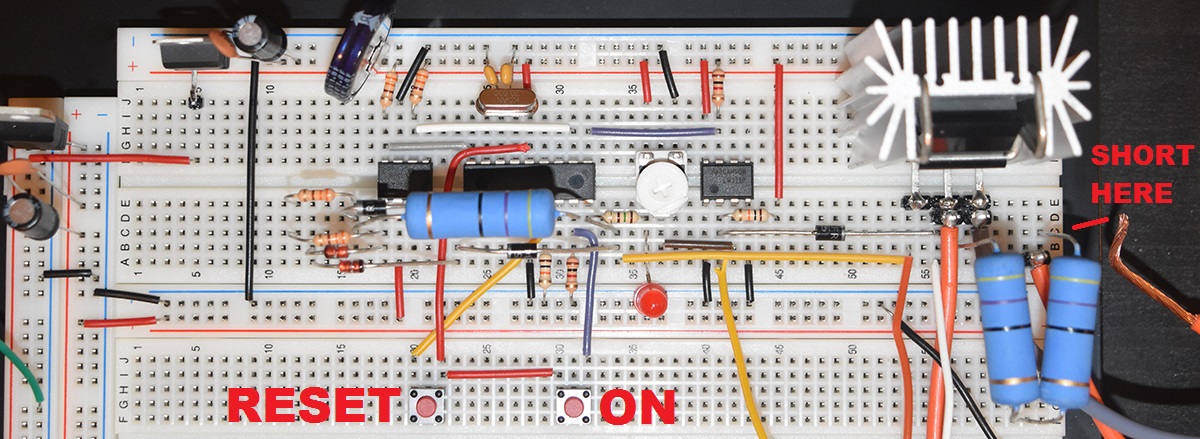
The program is as simple as it could be. The oscillator has been set to it's maximum of 20MHz which translates to an instruction cycle time of 200ns, plenty fast enough. The chip reads an input, in this case a push button but in the real world it would be PWM (although not in this circuit). When switched on there is a pause of 1us to allow the IGBT to turn on, it stops the desaturation detection from initiating. Afterwards it checks for a desaturation condition along with checking for the input dropping back to logic one. When over-saturation is detected it takes two outputs low, one is the driver and the other a clamp, the indicator LED illuminates. The program loops until the reset button is pressed.

The first test is simply a resistor between the driver and the gate of the IGBT.
Channel 1(yellow) is VCE, channel 2 (blue) is the gate and channel 3 (purple) is the input to the comparator.
A direct short cause VCE to rise, it crosses the threshold on the comparator causing the microcontroller to pull the driver low. The whole process takes 3us.
As you can see there is a huge voltage spike which is caused by inductance, not so good. There is also a spike at the comparator input, my fast recovery diode is not fast enough.

Again the same test except the probe for VCE has been set to x10.
As you can see the spike is around 350V whereas the supply is only about 20V.
If the spike is nearly 18 times the supply voltage then even with this 1200V IGBT could be destroyed at only about 70V. (There is an avalanche rating to survive this kind of thing to an extent).

For the second test the clamp resistor has now been changed to around 500 ohms, this resistor is between the gate and the low driver.
The whole process now takes around 17us but as you can see the voltage spike has now halved. This is known as a "soft" turn off.
The spike only occurs when the IGBT turns off, the IGBT remains on for the first 13us which is just wasted time, this is not ideal as high currents will over-heat the IGBT very fast,

The clamp resistor has been changed to 750 ohms.
The spike is now down to a much safer 70V, now the IGBT could be run around 340V with a safe short.
Reducing the turn-off time will reduce the voltage spike to an extent, a lot can be down to the power supply, I have a 3m total length of supply wires, these create inductance and therefore the voltage spike when turned off.

For the third test two 4.7V zener diodes and a regular diode has been placed between the gate and the clamp, the clamp is a second output of the driver controlled by the microcontroller.
The IGBT turns itself off at around 8V, so ideally we want to quickly drop it to 8.5V and then gradually drop it further to turn off the IGBT, this is known as a two-stage turn off.
The whole process is done in about 8us. This could be better since the diodes only work down to 10.1V. The final voltage is reduced by a 750 ohm resistor.

For my second test I chose to crank the supply up to around 60V.
The VCE spike is now 300V, it's not too bad but still not perfect. The wires from my supply are only 1.7mm and about 3m long so this inductance is really shooting up the voltage spikes.
The voltage spike is so great it is making it's way through my diode to the comparator. The diode is already a fast-recovery one, the choices are to get a faster one of have another way to cut this voltage spike.

This was another test with the discharge resistors being 330 ohm, as you can see changing this resistor has made very little difference.
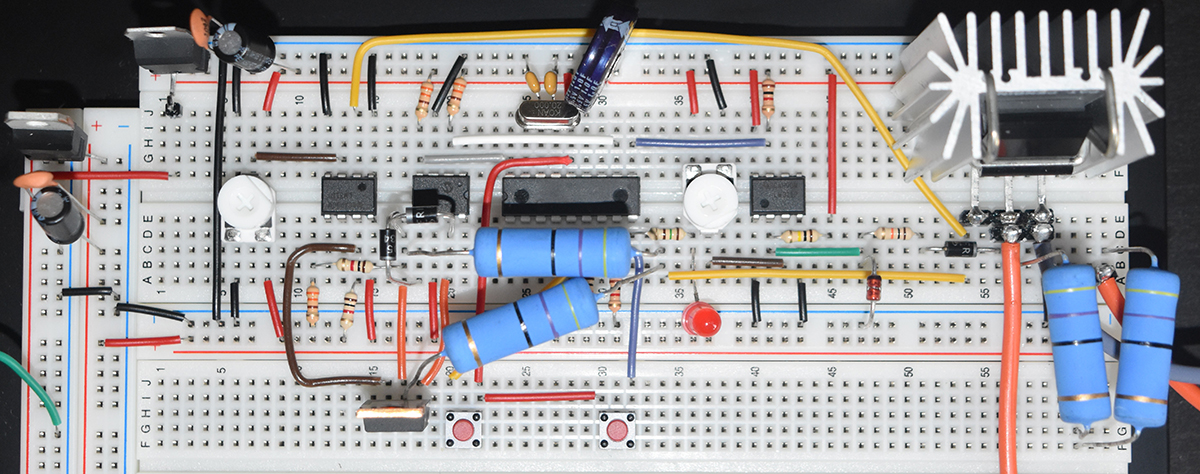
I have modified the circuit as I was getting a huge voltage spike passing through the diode to my comparator. Another problem was that when the fault occurred using a large resistor to "soft" turn off the IGBT wasted quite an amount of time before it actually turned off, I combated this by using a zener diode to quickly reduce the voltage down to 10V. For the next circuit I have removed the zener diodes and included a comparator. When the over-saturation is detected a MOSFET will pull down the gate, when the comparator reaches the preset level the MOSFET will release allowing the resistor to "soft" turn off the IGBT.
The first thing was to reduce the voltage spike at the input to the comparator, so I included an extra resistor to limit current and also a zener diode to limit voltage.
When the microcontroller is switching the IGBT on and off normally it will turn both gate drivers on and both off, one sinks current and the other sources current.
At the same time a clamp circuit runs that pulls the IGBT gate down until the comparator reads for example 10V, the MOSFET shuts off.
When over-saturation occurs it pulls only the sourcing driver down, the clamp circuit does it's job pulling the gate to 10V and then the 750 ohm resistor "soft" turns off the IGBT.
Here is the circuit built onto breadboard, I have reduced my gate drive resistor down to 23.5 ohm by placing two 47 ohms in parallel.

The purple trace is the over-saturation detector output from the comparator going to the microcontroller.
As you can see the performance of the zener diode in the previous setup is a lot more effective than the comparator and clamp in this circuit.
The one thing that this circuit has allowed me to do is find the optimum voltage the gate needs to be pulled down to before "soft" turn off. It turns out that between 9 and 10V is optimum for a safe "soft" turn off.
Hello, if you have enjoyed reading this project, have taken an interest in another or want me to progress one further then please consider donating or even sponsoring a small amount every month, for more information on why you may like to help me out then follow the sponsor link to the left. Otherwise you can donate any amount with the link below, thank you!