Microcontrollers 5 - Character LCD
This is where a lot of people try to start out with microcontroller programming as the "flashing LED" project doesn't sound all that interesting. While it's not all that difficult to get a character LCD to work it can require a lot of code and be quite daunting for the beginner, infact this is quite a jump, a great place to start is with the LCD itself. Nearly all of the LCD's are based on something called the "Hitachi HD44780" which is a standard for most LCD's. Two datasheets worth reading are; PDF1 and PDF2
Below is a very useful extract from either datasheet.
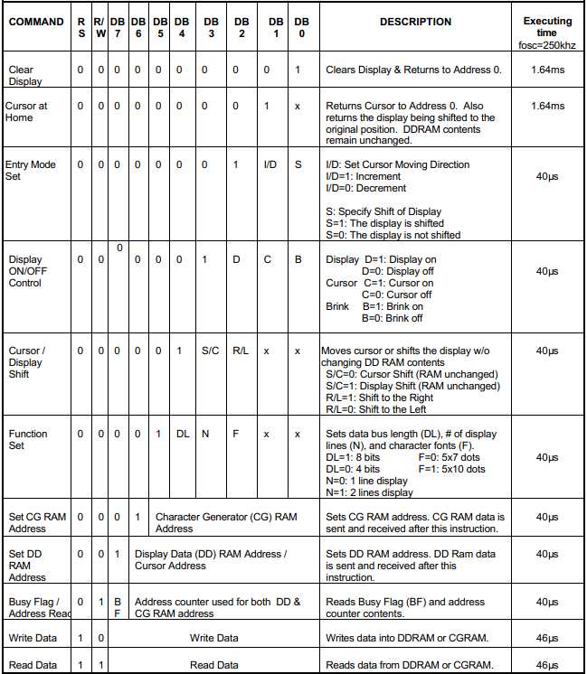
There are several important pins on a character display, check the pinout diagram in datasheet one for where they are.
E - Enable - when active this allows data to be sent or received.
RS - Register select - This determines whether you are sending an instruction to the screen or data.
R/W - Read / Write - You can either write to the LCD or read from it. Normally this pin is tied to ground so you can only write to it.
DB0 - DB7 - Databus 0 - 7 - This is what you send the information through, it can be sent in 8-bit or dual 4-bit. The dual 4-bit allows the use of just four pins, the upper bits sent first and the lower bits sent second, DB4 - 7 are used in this mode. 4-bits are known as nibbles, you would send the high nibble and then the low nibble.
Say for example I want to clear the display and then send the letter "A".
I would first set RS to logic 0 which tells the LCD to accept an instruction. Now because we're using 4-bit mode I would then send 0000 , E logic 1, pause, E logic 0, then send 0001, E logic 1, pause, E logic 0. That has now told the screen to clear.
RS would be set to logic 1 to enter data mode. The letter "A" in binary would be 01000001. So I would send 0100, E logic 1, pause, E logic 0, then send 0001, E logic 1, pause, E logic 0. The letter "A" is now in the display.
A series of subroutines would be used in this process such as for the enable and a subroutine that breaks the 8-bits into two 4-bit nibbles. Sufficient pauses must be implemented to allow the execution time, as shown in the datasheet to the left.
One thing it doesn't always tell you in the datasheet is how to initialise the LCD first, for your convenience I have created a flow chart below. The LCD when powered up will believe itself to be in 8-bit mode, we need to change this to 4-bit mode. Before this can be done the LCD module first needs to be reset, this requires DB4 and DB5 to be high, the enable needs to be pulsed 3 times, then DB4 is set low and the enable pulsed again, this has reset the display and placed it in 4-bit mode. After it's been set to 4-bit mode all of the required settings on the display need to be sent, once complete the LCD has initialised.
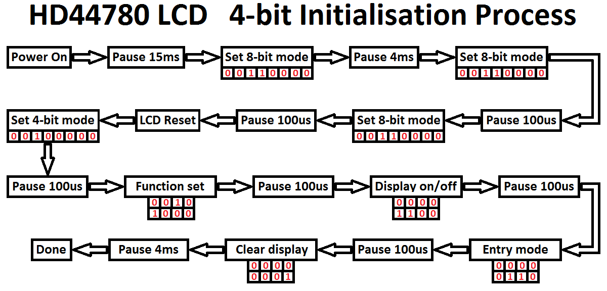
Below is a table of the steps involved and what must be done to each of the pins. Note that some of the delays are larger, these are to ensure that the LCD can keep up, sometimes their oscillators can run a little slow. I have included the reset, 4-bit mode and the first instruction "Function Set", you should be able to understand from there on how to send the other settings. To send a character the R/S pin would be set high and the same procedure of sending the high nibble and then the low nibble would be implemented.
| Step | Description | R/S | Enable | DB7 | DB6 | DB5 | DB4 | Comments |
|---|---|---|---|---|---|---|---|---|
1 |
Power Up |
0 |
0 |
0 |
0 |
0 |
0 |
|
2 |
Pause 15ms |
0 |
0 |
0 |
0 |
0 |
0 |
|
3 |
Set 8-bit |
0 |
0 |
0 |
0 |
1 |
1 |
|
4 |
Enable on |
0 |
1 |
0 |
0 |
1 |
1 |
|
5 |
Pause 1us |
0 |
1 |
0 |
0 |
1 |
1 |
|
6 |
Enable off |
0 |
0 |
0 |
0 |
1 |
1 |
|
7 |
Pause 5ms |
0 |
0 |
0 |
0 |
1 |
1 |
|
8 |
Enable on |
0 |
1 |
0 |
0 |
1 |
1 |
|
9 |
Pause 1us |
0 |
1 |
0 |
0 |
1 |
1 |
|
10 |
Enable off |
0 |
0 |
0 |
0 |
1 |
1 |
|
11 |
Pause 600us |
0 |
0 |
0 |
0 |
1 |
1 |
|
12 |
Enable on |
0 |
1 |
0 |
0 |
1 |
1 |
|
13 |
Pause 1us |
0 |
1 |
0 |
0 |
1 |
1 |
|
14 |
Enable off |
0 |
0 |
0 |
0 |
1 |
1 |
|
15 |
Pause 600us |
0 |
0 |
0 |
0 |
1 |
1 |
Module has been reset |
16 |
Set 4-bit mode |
0 |
0 |
0 |
0 |
1 |
0 |
|
17 |
Enable on |
0 |
1 |
0 |
0 |
1 |
0 |
|
18 |
Pause 1us |
0 |
1 |
0 |
0 |
1 |
0 |
|
19 |
Enable off |
0 |
0 |
0 |
0 |
1 |
0 |
|
20 |
Pause 600us |
0 |
0 |
0 |
0 |
1 |
0 |
Module in 4-bit mode |
21 |
High nibble |
0 |
0 |
0 |
0 |
1 |
0 |
|
22 |
Enable on |
0 |
1 |
0 |
0 |
1 |
0 |
|
23 |
Pause 1us |
0 |
1 |
0 |
0 |
1 |
0 |
|
24 |
Enable off |
0 |
0 |
0 |
0 |
1 |
0 |
|
25 |
Pause 600us |
0 |
0 |
0 |
0 |
1 |
0 |
|
26 |
Low nibble |
0 |
0 |
1 |
0 |
0 |
0 |
|
27 |
Enable on |
0 |
1 |
1 |
0 |
0 |
0 |
|
28 |
Pause 1us |
0 |
1 |
1 |
0 |
0 |
0 |
|
29 |
Enable off |
0 |
0 |
1 |
0 |
0 |
0 |
|
30 |
Pause 600us |
0 |
0 |
1 |
0 |
0 |
0 |
Function set sent |
The program below will first initialise the LCD, it will then call up a subroutine to send a series of characters to the display. One thing to note with an LCD is that only one character is sent at a time, so if you want to display "hello" then the "h" would be sent followed by the "e" and so on. There are many ways of doing such a task, one of those involves something called a "lookup table" or "data table" which I have included towards the end of my program. For your convenience here is a copy of my - Program
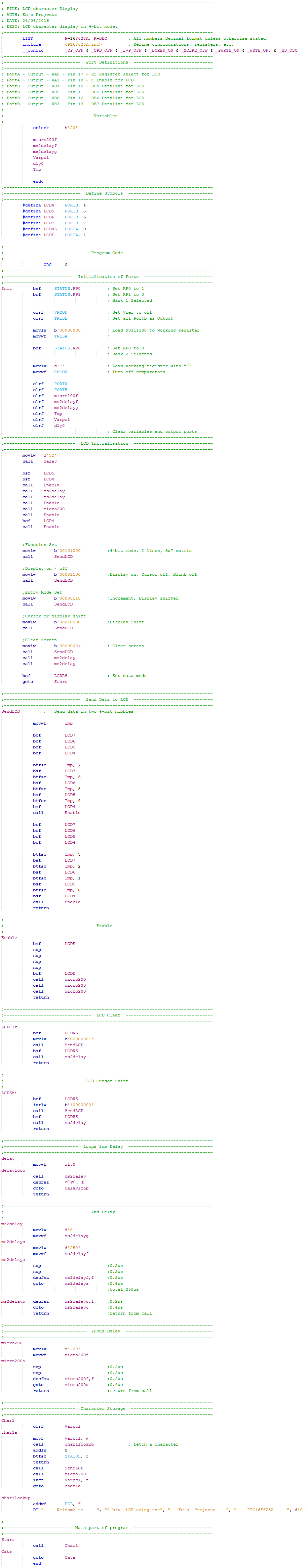
Firstly all of the configurations are set, it is worth noting that the oscillator is external and set to 20MHz.
List all of the variables, h'20' is the start of the RAM location in hex, there is a maximum of 96 starting from this particular slot.
All of the registers or even the specific bits of a register can be defined as a symbol. This makes it a lot easier to understand what your doing with the ports in a program.
Set all of the ports as outputs, one of the comments is incorrect.
Variables should be zero on start-up of the microcontroller, it is always a good idea to ensure they are zero.
The first two commands set a delay to loop 32 times, each cycle 2ms.
This is the initialisation sequence that resets the LCD module and sets it to 4-bit mode.
These are the instructions to the LCD, it says in the notes what these do as well as in the table at the beginning of this chapter.
Most of the instructions take a duration of around 50us whereas the clear screen instruction will take around 2ms. These delays in the first table are the fastest the LCD can process, it's normally a good idea to atleast double these delays as the oscillator can be unpredictable.
When the data needs to be sent to the data bus in 4-bit mode the program calls to this section. The value is loaded to the working register before this section is called upon.
So firstly the value in the working register is placed in a variable so it can be split up.
The data lines to the LCD are first cleared and then each bit in the variable is tested, if zero it will check the next bit, if one it will set the data bit going to the LCD.
The top four high bits are checked first, the enable subroutine tells the LCD to accept the data.
The lines are cleared once again and the lower four bits are checked. These are then sent to the LCD.
The program returns from where it left off.
This sends a pulse to the LCD telling it to accept data. The enable pin is only required to be on for around 200ns, so 800ns is sufficient to do the job.
A long pause after the bit is set to zero is required to allow the data enough time to be written.
Here are a couple of separate programs, these are called up as subroutines instead of writing the program out multiple times.
This program sets the address of the data to be written, it is used to shift the cursor.
This is the loop program for a delay, whatever is pre-loaded into the working register is the number of times that this delay will loop, in multiples of 2ms.
This is the information to be sent and displayed on the LCD.
The variable Varpcl is cleared, it is temporarily added to the PCL, the program counter. The first character after the "DT" is placed in the working register, it returns to add 0 to the register, if the result is zero it will return from where it was called. If not it will send this character to the LCD.
Afterwards the variable Varpcl is incremented by one, the program loops. This time the PCL is one, meaning that when it reads "DT" it will read one character to the right from the previous time.
When the datatable reaches it's end, d'0' is added to zero causing one to display in the Z register making it return from the call.
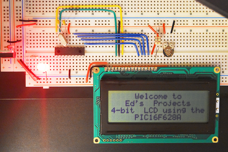
Below is a visual representation of the circuit on a breadboard. Note that I have removed the programmer from the circuit as it is best to program a chip on a separate board as explained in the previous chapter. Firstly there should be a resistor between the backlight and it's source, around 50 ohms. Secondly the contrast potentiometer for my LCD was set to 0V for the characters to be clear.
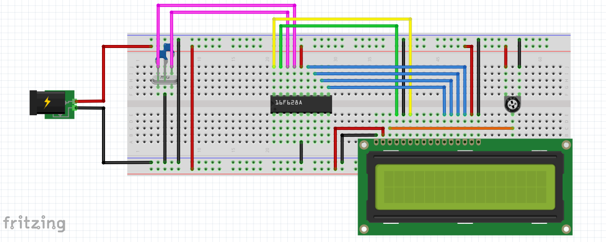
Below is my version of the character LCD on my breadboard, notice that I have used a larger character display, this is ok as they are run exactly the same, you may just need less spacing between characters in your program.
You may have noticed that writing a message in the lookup / data table was not just one single line and it's also jumbled up, this cannot be helped because it's the way that the LCD is construction. The LCD is made up of two data lines, the data is written to line 1 first and then line 2 afterwards. The first data line corresponds to row 1 and 3 of the display whereas data line two corresponds to row 2 and 4 of the display. Due to these circumstances it means that when you send data to the LCD the first 20 characters will be row 1, the next 20 row 3, the next 20 row 2 and the next 20 row 4. Another way is to direct the characters where to start, the only problem is this adds several more instructions when it's easier to just place a few spaces in the data table.
The two lines in the LCD are known as the DDRAM which is basically the cursor position as mentioned above, below is an example of these addresses in hex.
00 |
01 |
02 |
03 |
04 |
05 |
06 |
07 |
08 |
09 |
0A |
0B |
0C |
0D |
0E |
0F |
10 |
11 |
12 |
13 |
14 |
15 |
16 |
17 |
18 |
19 |
1A |
1B |
1C |
1D |
1E |
1F |
20 |
21 |
22 |
23 |
24 |
25 |
26 |
27 |
|---|---|---|---|---|---|---|---|---|---|---|---|---|---|---|---|---|---|---|---|---|---|---|---|---|---|---|---|---|---|---|---|---|---|---|---|---|---|---|---|
40 |
41 |
42 |
43 |
44 |
45 |
46 |
46 |
48 |
49 |
4A |
4B |
4C |
4D |
4E |
4F |
50 |
51 |
52 |
53 |
54 |
55 |
56 |
57 |
58 |
58 |
5A |
5B |
5C |
5D |
5E |
5F |
60 |
61 |
62 |
63 |
64 |
65 |
66 |
67 |
Or the table in decimal.
| 0 | 1 | 2 | 3 | 4 | 5 | 6 | 7 | 8 | 9 | 10 | 11 | 12 | 13 | 14 | 15 | 16 | 17 | 18 | 19 | 20 | 21 | 22 | 23 | 24 | 25 | 26 | 27 | 28 | 29 | 30 | 31 | 32 | 33 | 34 | 35 | 36 | 37 | 38 | 39 |
|---|---|---|---|---|---|---|---|---|---|---|---|---|---|---|---|---|---|---|---|---|---|---|---|---|---|---|---|---|---|---|---|---|---|---|---|---|---|---|---|
| 64 | 65 | 66 | 67 | 68 | 69 | 70 | 71 | 72 | 73 | 74 | 75 | 76 | 77 | 78 | 79 | 80 | 81 | 82 | 83 | 84 | 85 | 86 | 87 | 88 | 89 | 90 | 91 | 92 | 93 | 94 | 95 | 96 | 97 | 98 | 99 | 100 | 101 | 102 | 103 |
The LCD has to be placed into instruction mode and have value h80 or 128 decimal added to the above number to choose the cursor position. This is a useful way of reducing write time, it is a big help with data entry.
So now you have the template to output a message from a character LCD, maybe you want to have some kind of an input to change the display message, it would be good practice to do so before moving to the next chapter.
Hello, if you have enjoyed reading this project, have taken an interest in another or want me to progress one further then please consider donating or even sponsoring a small amount every month, for more information on why you may like to help me out then follow the sponsor link to the left. Otherwise you can donate any amount with the link below, thank you!