Morse Taper 4.5?
Quite a common spindle bore for a medium sized lathe is the morse taper 4.5 (MT4.5). The reason for this is because the morse taper 4 would have a spindle bore of about 26mm and the morse taper 5 would have a spindle bore of about 39mm, these are just approximates and may vary slightly between lathes. Now the difference in these two values is quite tremendous considering this would be the difference between a 100kg lathe and a 1 tonne lathe. A lot of medium sizes lathes opted to go for a morse taper 4.5 which has a spindle bore of about 35mm making the lathe a decent size for the average workshop. My lathe is a Harrison M250 which has a spindle bore of 35.5mm and the morse taper 4.5 nose and even though these lathes and many similar were mass produced the MT4.5 adapter is pretty rare.
So I chose to make my own.
January 06/01/2016
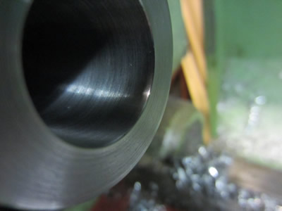
The first thing was to find out what MT4.5 actually is as each morse taper has a slightly different angle, or size ratio. I would assume that it would be half way between, but it turns out it's the same angle as MT4 but the diameters are halfway between MT4 and MT5. The only important considerations are to what will suit the lathe, so I used the ratio but took the diameters from my lathe, sounds a little cryptic. The largest diameter of my spindle nose is 38.2mm and the size ratio is 1:19.2308, this means that for every 1mm in diameter it moves 19.23mm in length. So if I take a nice round number of 100mm to be the length of the taper and the larger diameter to be say 39.2mm then the minor diameter of the taper would be (39.2 - (100/19.2308), which is 34mm (under the spindle bore, which it needs to be). All of the sizes sound about right, the taper smaller at one end to fit down the bore and larger at the other to stop it going all the way through the bore.
If anyone is working in inches then the taper per foot is 0.624, I got the ratio by 12 inches divided by 0.624. ( 12 / 0.624) = 19.23076923.
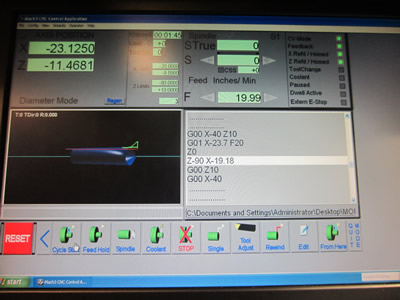
A morse taper works on the fact that surface contact causes it to grip, the shallower the angle the more surface and the more grip, there is a slight bit more to it than that but that's the basic principle. Now this only works if the contact is all the way down the taper which therefore means that both the bore and the adapter must have exactly the same angle. There is no way that I could possibly do this accurately at a length of 100mm with the compound which meant that the CNC had to be used, thank goodness I have it as I don't know how else it could be done.
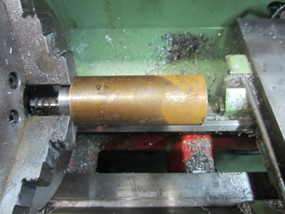
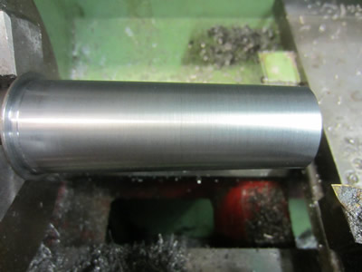
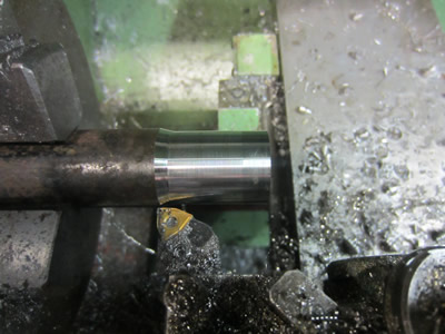
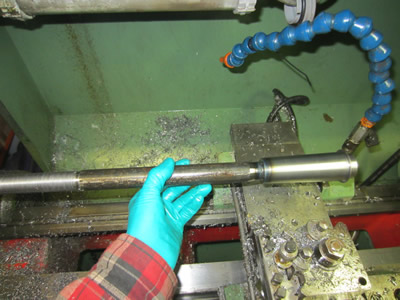
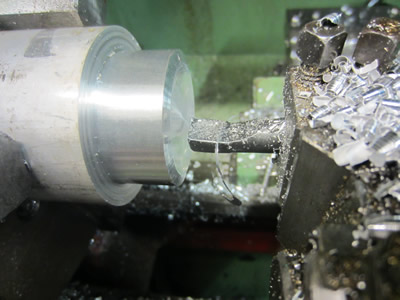
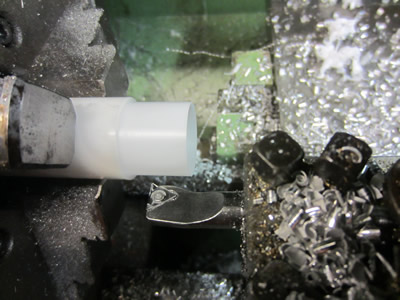
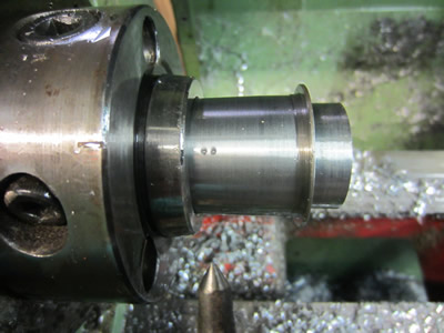
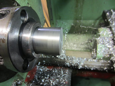
I started out with an offcut of steel, I think it's EN1A but I'm not too sure. I had been machining some steel earlier and found that the faster I could get the spindle the better the finish would be, so I chose 1000rpm and a feed of 0.075mm/rev. I was quite astounded of the finish as mild steel is notorious for the finish tearing, but if it is EN1A then it would machine easier. After I cut the outside from 45mm down to 40mm using 1mm cuts I went ahead with writing a program to cut the outside taper.
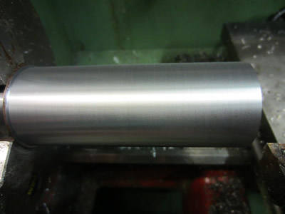
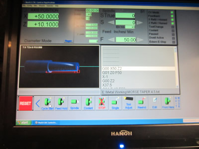
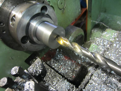
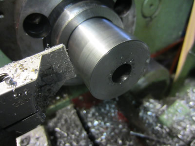
I chose to cut it in a series of several steps and then two final passes, the finish pass being 0.6mm at a feed of 100mm/minute. The CNC scares me a little as there are no proper guards and I don't trust the software, I haven't had an incident yet, but you have to be cautious. I ran the final pass at a speed of 2000rpm and held a large piece of acrylic plastic in front of me, safety first, the finish came out to be excellent but I can't see me ever using that speed again. The end was drilled and bored out to suit a drawbar, I was going to thread it but figured welding would be a better option for simplicity, there wouldn't be much load on it either as the taper does the work.
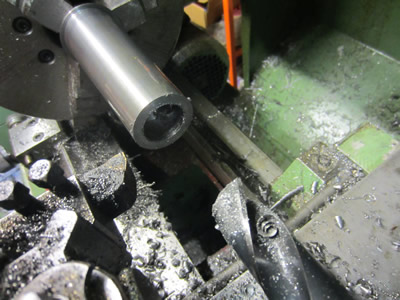
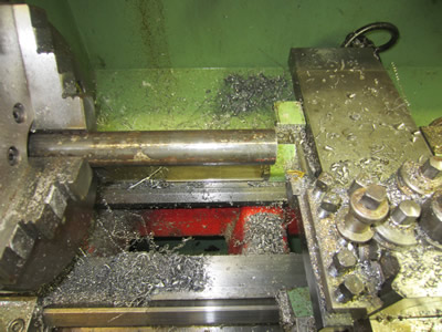
The drawbar was made from a piece of steel tubing, not the same grade but very similar and definitely a higher carbon content.
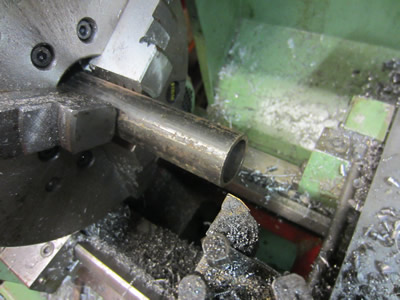
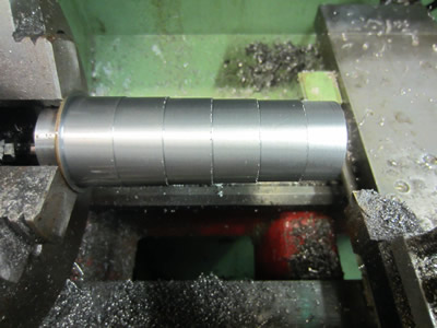
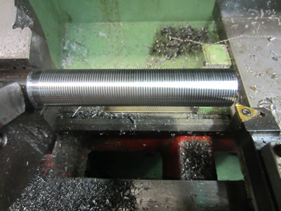
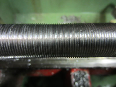
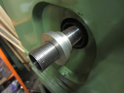
The opposite end was prepared for threading, the tube was sticking out 150mm so I was expecting chatter. The last picture shows a groove where the half-nut can be disengaged, so I didn't break the insert.

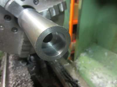
The threading process was done as fast as I dare to keep the finish good, 600rpm. The thread came out alright but certainly not the best I've turned, the centre picture is an optical illusion looking as if it dips in the middle, it doesn't. The tube was pressed into the adapter I made earlier and then TIG welded in place.
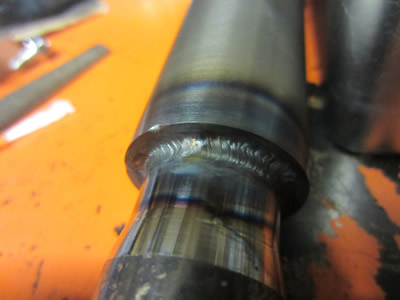
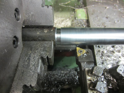
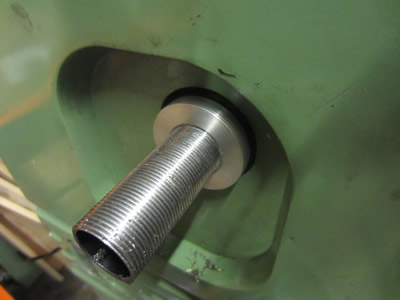
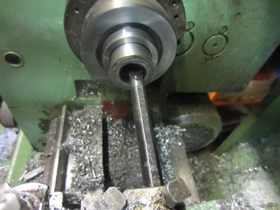
The drawbar was inserted into the nose of the lathe to make sure I had got the taper right, it was perfect.
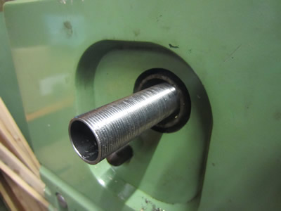
I started to make a bush out of aluminium to centre the drawbar tube in the spindle.
I made a mistake on the inside of the bush so I had to make a thin sleeve out of plastic to compensate for the error, only a wall of 0.5mm. Once a nut has been made for this tube I can then proceed with machining the MT3 bore into my adapter, the reason for using tube is so that a second drawbar can be placed down the centre for the MT3 attachment.
January 07/01/2016
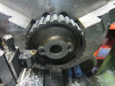
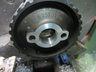
The first thing on the list was to finish off the nut for the draw bar, I was going to make one from scratch and then mill on a hex but I found an alternative. From an engine rebuild I ended up with a scrap top end pulley, it was made from a magnesium alloy and I figured that it should be fine for a thread. I started by facing the front to ensure an even contact surface when tightening, I also prepared the bore for threading.
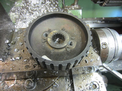
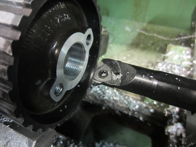
The bore was threaded to suit the draw bar of M26 x 1.5, and then the ouside height was shortened to provide some clearance to the gear housing. I was a little woried that the drawbar could have been a little rough causing "sticky threads" but it turned out fine, probably aided by the properties of the magnesium alloy.
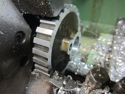

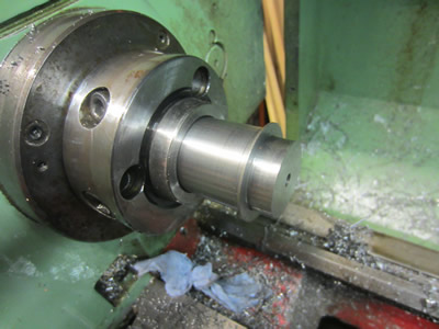
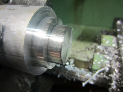
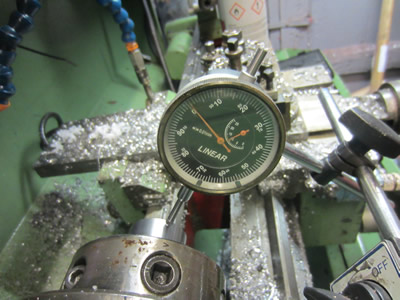
I put a clock against the adapter to make sure it was running true, a total runout of 0.015mm which seems a little excessive. I'm going to put it down to the bore as there is absoloutely no reason why the adapter would be tapered. I chose to put two punch marks so that in future I can set it in the same place. I shortened the outside by about 15mm but it needed another 20mm or so taking from it, so I drilled out the inside first to aid with parting.
I turned down the face so that about 20mm was protruding from the nose, the last picture shows the 0.015mm runout.

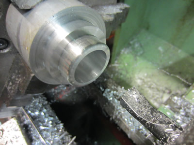
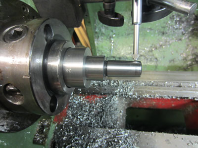
The inside taper was going to be MT3 at a length of 90mm, so the first thing I did was bore it out to 20mm as this was the minimum diameter a MT3 tung would pass. I used an aluminium insert as these are very sharp and should/would give an excellent finish. The first picture shows me using a regular boring bar with a stainless insert but the finish proved to be pretty rubish, I chose to clock the boring bars straight as there was little clearance. I used the CNC again to get the correct angle, the boring bar had to be pulled out 120mm due to the carriage hitting it's limit.

Due to the length of the boring bar and it's sharpness I had to run the spindle at 240rpm at a feed on 20mm/minute, any faster and it would have caused chatter. The bore came out to an excellent finish, I inserted an MT3 arbor to test the result. The arbor immediately got stuck which meant it was perfect, I tested the runout and it was also perfect, which it should be.
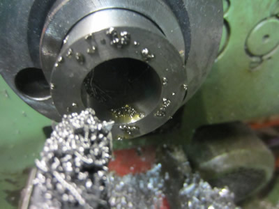
Overall I'm really happy with the result and no mistakes were made on making the adapter, thankfully. The one thing I'm not happy about is the little amount of surface contact inside of the spindle, there is one 15mm section spaced by 30mm to a 10mm section. It's not really a design fault of the lathe as morse tapers are meant to work axially and not radially, therefore intended only for drilling. This adapter can be used for turning as I have a draw bar in place, but I would only take light cuts.
Hello, if you have enjoyed reading this project, have taken an interest in another or want me to progress one further then please consider donating or even sponsoring a small amount every month, for more information on why you may like to help me out then follow the sponsor link to the left. Otherwise you can donate any amount with the link below, thank you!