Billet Connecting Rods and Pistons
The stock connecting rods in a naturally aspirated engine were not intended for the extra power of a boosted engine. The engine these rods are intended for are a Hyundai Beta engine which gives out around 140bhp stock. I have heard plenty of stories that the stock rods are capable of around 400bhp, this is at the limits however. The reason to machine some billet rods is that they can be made to much tighter tolerances and a better grade of steel.
The weakest point of a stock engine is usually the pistons. A stock piston is made from an aluminium alloy with a very high silicon content, this gives it excellent wear properties and low thermal expansion. A naturally aspirated engine runs at a compression ratio of around 10:1 whereas a boosted engine will run at around 8.5:1. Lowering the compression ratio decreases the peak pressure of a knock event. Boosting a naturally aspirated engine greatly increases the risk of a fractured piston due to knock.
Aftermarket pistons are normally made from a much softer grade of aluminium which allows them to sustain knock without failure. The issue is that this material has lower wear properties and a much higher rate of thermal expansion. These pistons have to be made smaller due to expansion when hot, this means there is a lot of piston slap when cold. These are great for a race car that is constantly at the limit but terrible for an every day driver.
So first is the stock rod in which I have made a rough CAD below. These are powdered metal pressed into a form and then baked. Sintered rods are very strong but these are not meant for the higher torque of a boosted engine.
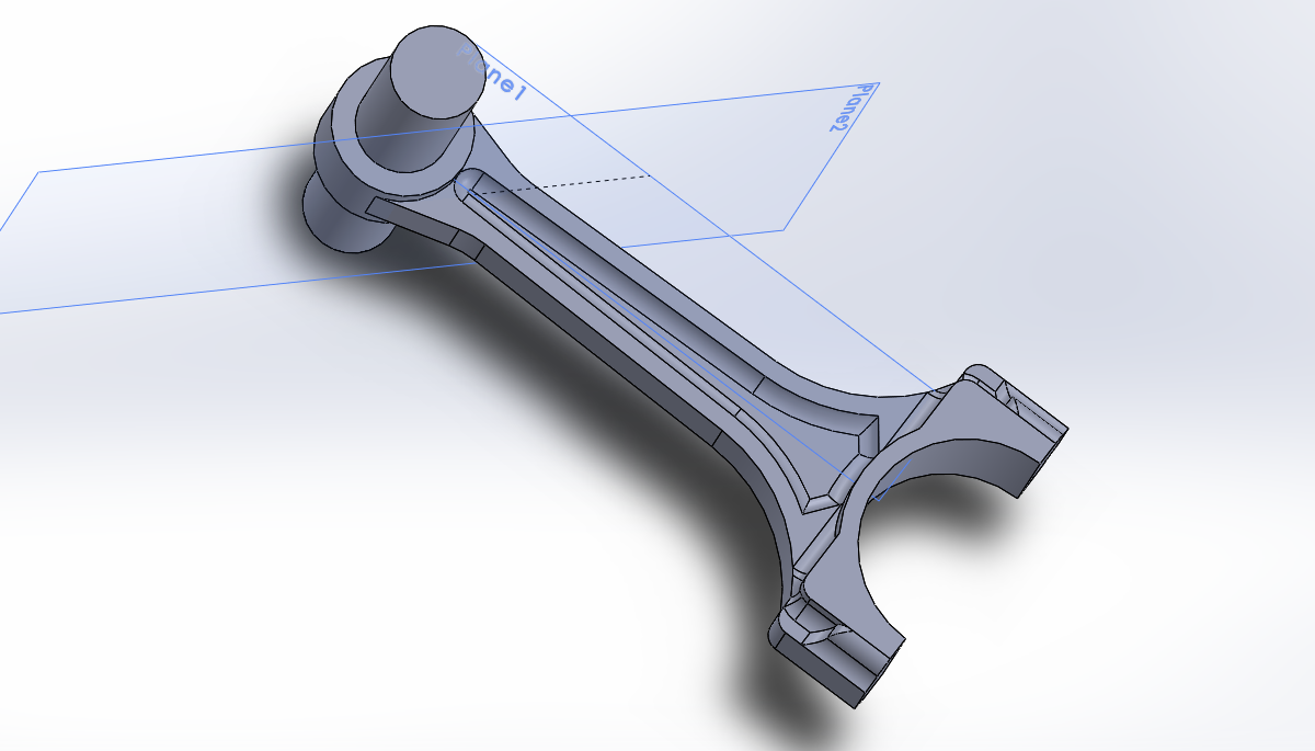
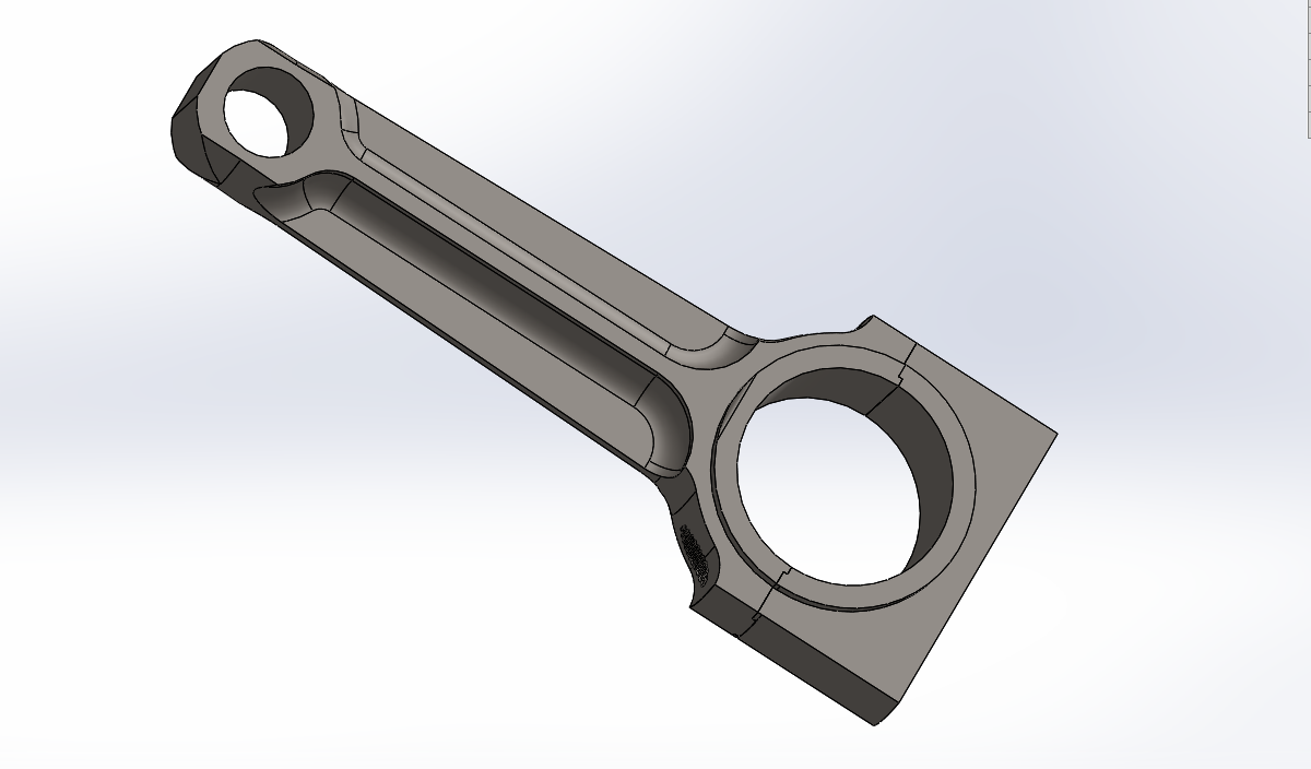
I made a design basing on that the majority of it will be turned, it is due to the machines I have access to at the time of writing this. The difference with this design is that the rod has been widened in the direction of rotation, this gives it hugely better torque withstanding capabilities. The width support has been slightly lessened, this will make little affect to the strength but will greatly reduce weight. I have not yet finished designing the cap yet.
I chose to go with 4340HT steel alloy as this is pretty much the standard for high performance parts. I machine 4140HT daily which is a fairly nice material, with this stuff I literally only get a tenth of the time out of an insert. I used 3 inch solid round bar, this stuff is expensive.
There is a huge amount of waste, it's not such a big deal on this part as they're one-off prototypes, way too much waste on a production run. These rods are very long for a performance application, it is likely that I won't even be able to run a higher engine speed. A longer stroke than bore (over-square) is used for economy applications as the engine produces a lot more torque, the length of the components limits the redline due to centrifical forces. A larger bore than stroke (under-square) is for racing applications as the smaller components allow for a much higher engine speed.
The rod caps would need some way of securing to the rod itself, the most common way is to use dowels. Regardless I would need to make some kind of a fixture to hold them since they're tapered.
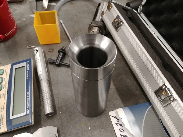
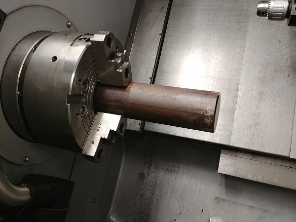
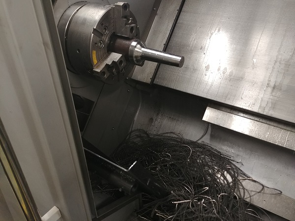
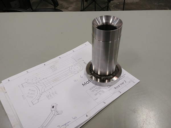
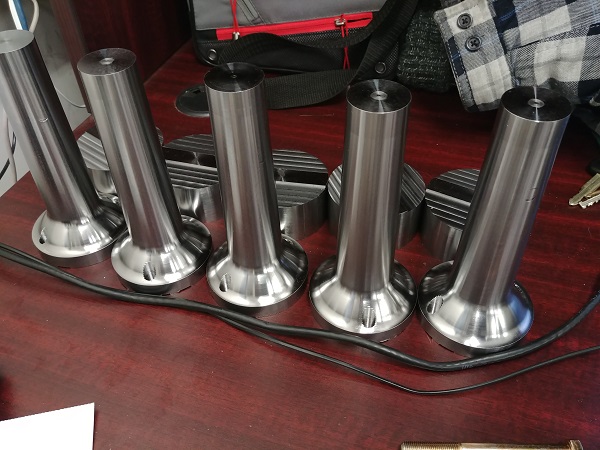
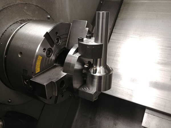
I got some 4140HT steel and turned out a reverse profile of the rod. I used an anti-vibration bar for the bore, these things are absolutely amazing. I then turned a ring to be press fit on the bottom, this will serve as something to clamp onto in the mill.
I pressed the spacer on, placed it in the lathe and made some adjustments to make sure that the top face ran true. I then removed it from the lathe and placed a bead of weld all the way around the top.
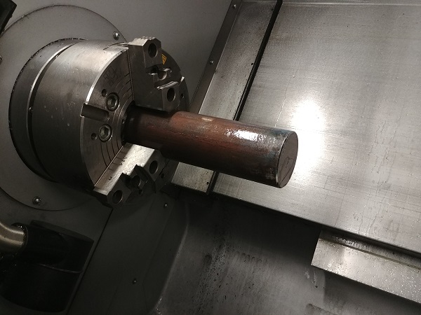
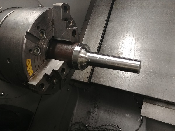
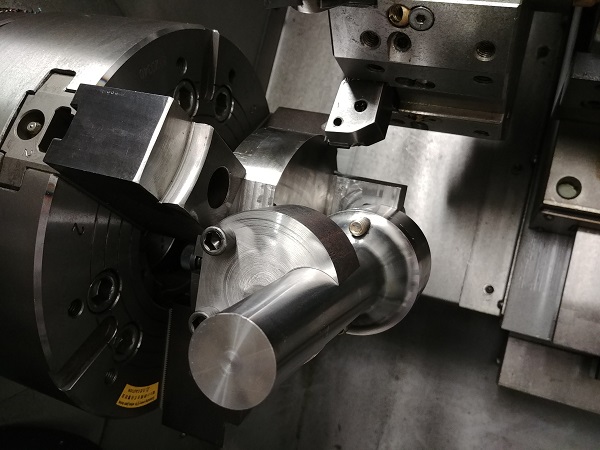
I placed it back in the lathe, turned the outside and the face true.
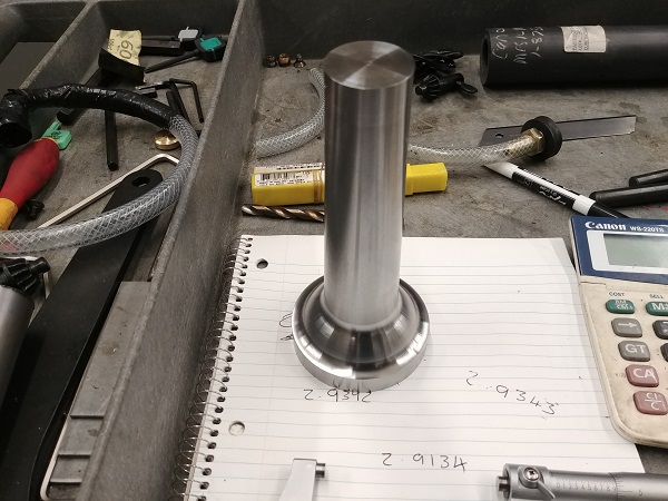
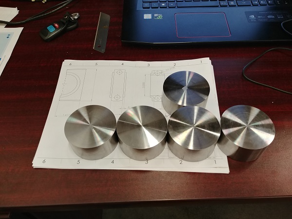
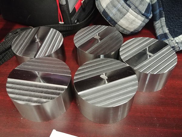
I also turned the pucks that will serve as blanks for the rod caps.
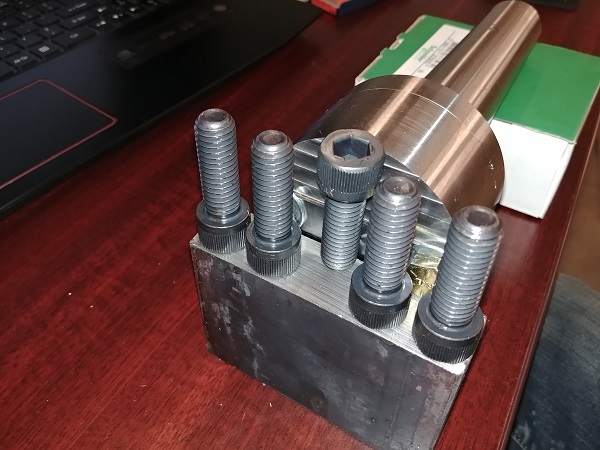
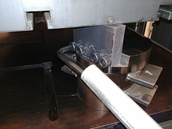
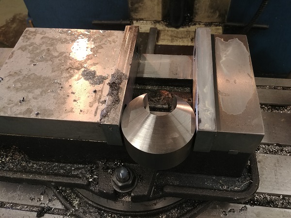
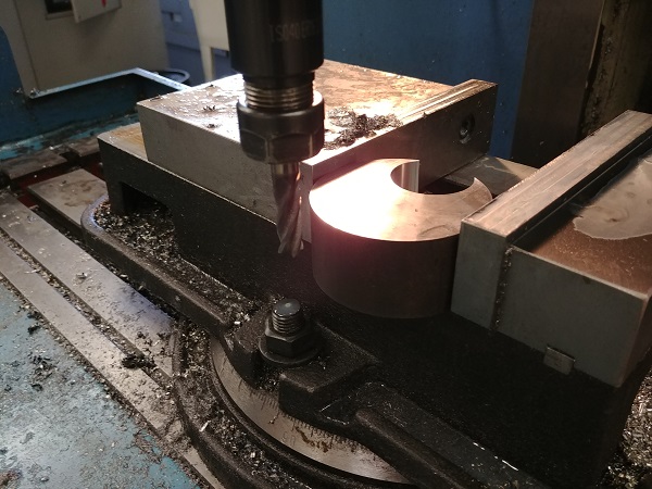
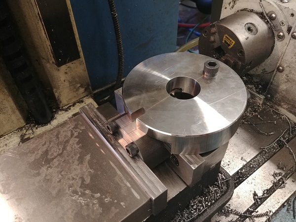
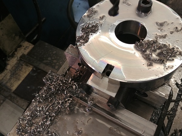
I placed the rod holder in the mill, two holes were made opposing each other, threaded and then bolts placed to hold the rod itself.
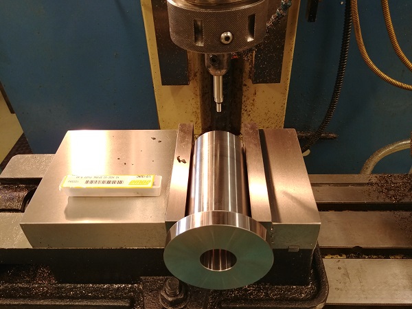
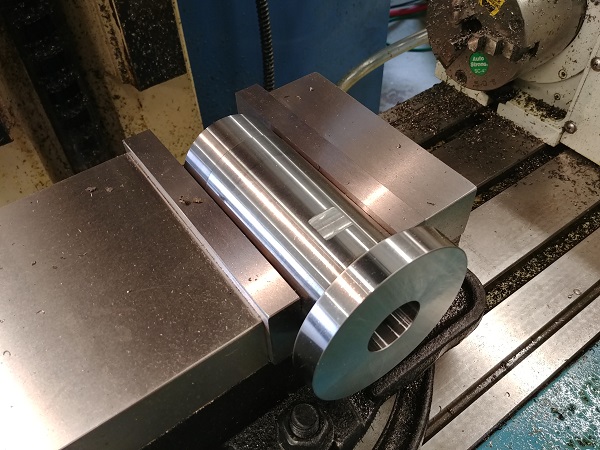
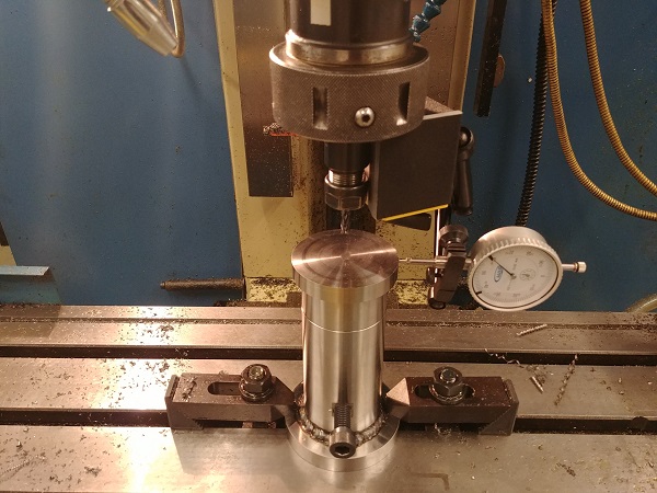
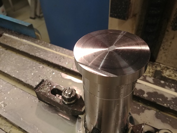
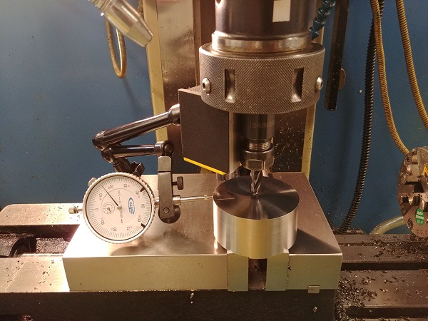
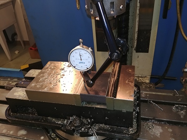
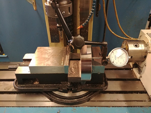
I used a hydraulic press to hold the rod in the holder while I tightened the bolts. If I did not press it together then I would not be able to ensure that the bolts would not lift the rod as I tightened them. If the rod was not in contact inside the holder then there would be the possibility it wouldn't be held straight, or even be rigid when milling. I bolted the holder in the mill and then clocked the part central. I did a little skim manually so that I could set the Z offset and mill the part height correctly.
I programmed the part manually as I did not have access to CAM software at the time of writing this. I chose to go a slightly different route as to locating the cap to the rod. Normally this would be done with a dowel, it's simple and the cap sits relatively stable. I chose to go with my own design that allows the cap to sit in slots, this will allow no cap movement at all.
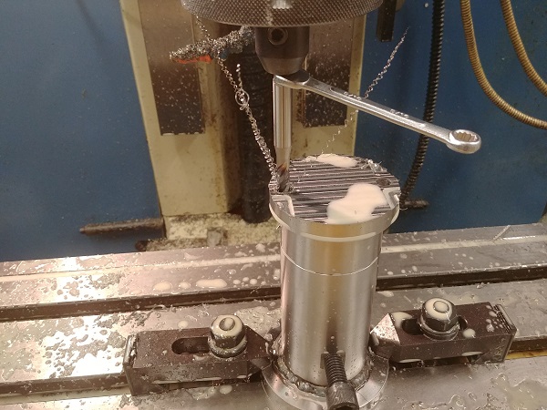
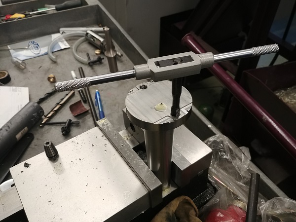
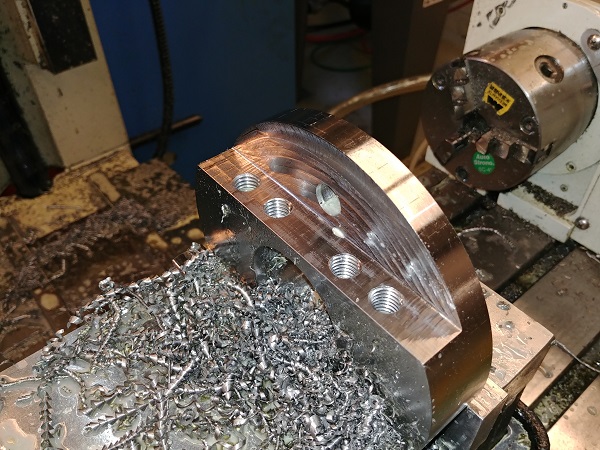
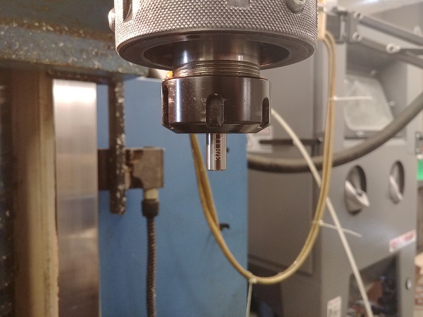
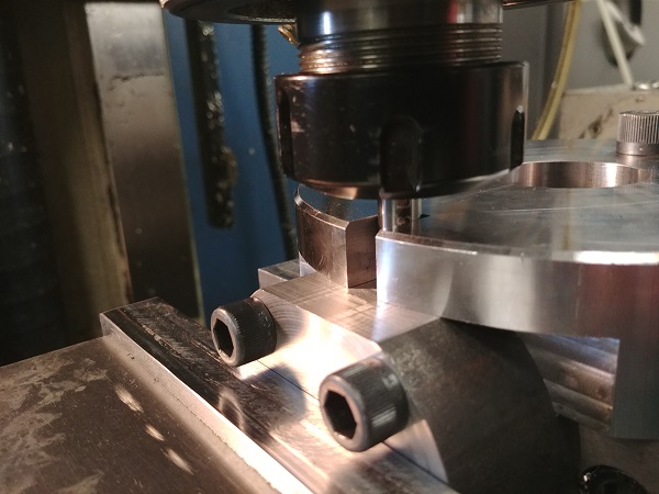
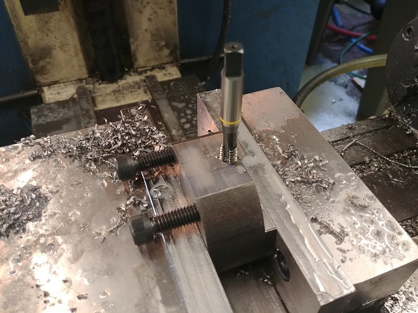
I wanted to use the mill to tap the holes for the bolts but I had to do it by hand. I chose to go with a spiral flute tap and used a milling holder to centralise the tap over the hole. I used a spanner to turn the tap, even though it was a spiral flute and a fine pitch it was still pretty tough. I then started work on the caps, first I clocked them true in the mill.
I milled a square section on the bottom of the caps, this will serve as working holding.
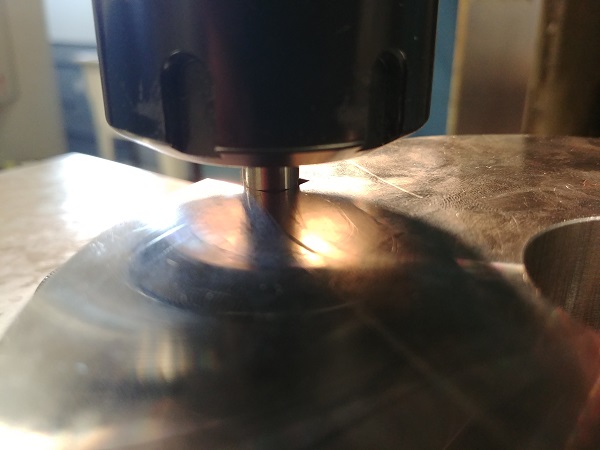
The break through of the hole is at an angle, not the best situation for a spiral flute tap. I threaded the remainder of the holes manually with a regular tap.
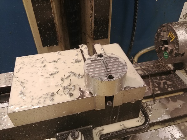
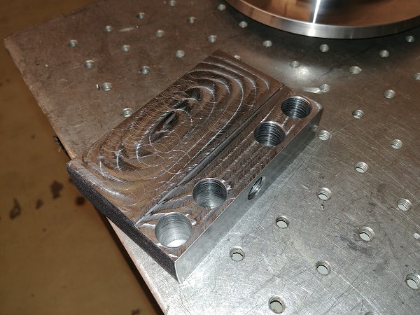
It is quite a time consuming task when working on parts such as these, the problem is that every individual one has to be setup. If this was a larger run then I would be sure to make a fixture of some kind. I milled the top of the vise flat and placed a puck in it.
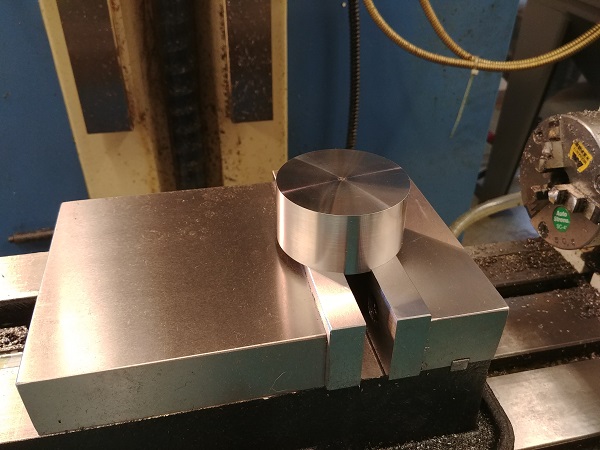
The puck was clocked to find the centre point and a skim taken in order to adjust for the correct height. I milled out the reverse pattern for the slots. The holes for the bolts were drilled and reamed out.
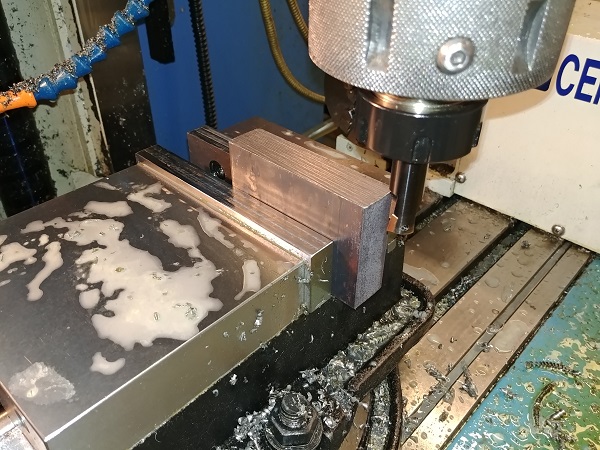
Machining the flats on the sides of the rods would ideally be done on a milling machine, unfortunately the one I have access to is not up to the task. I designed the rod to use as many operations on the lathe as possible. I found out a piece of scrap steel to make a jig out of, a piece of 4140HT, so it should be solid. I clocked it in the mill and then proceeded to making these flats larger, but also precise.
I got a piece of 1 inch thick mild steel to make a platform for the rod to sit on. There was quite a bit of work aligning this and getting all of the faces running straight.
I managed to miss out some pictures of the process but I got it all bolted together, trued up and milled a pocket for the bottom of the rod to sit in.
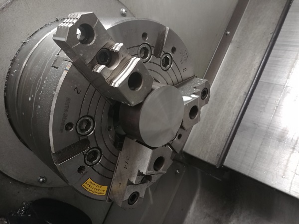
The caps are a very tight fit to the rods, the parts came out great. The slot for the cap to fit in the jig is also a very tight fit. I would next need to make something to secure the top of the rod. I worked out a quick design using some of the left-over 4340 steel, it would need a tapered offset bore. The offset of the bore would need to be between 24 and 25mm from the centre of the billet, I used a caliper and a punch to mark this out.
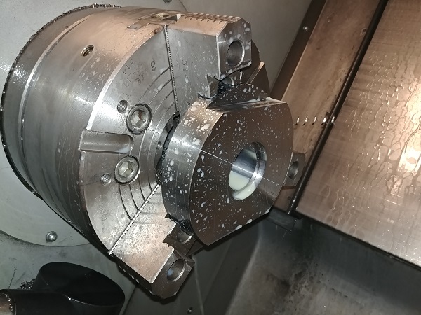
The lathe I use has a hydraulic chuck, I do have the use of a 4-jaw independent but it's too much work swapping it over for such a small operation. I instead backed one of the jaws out until a centre drill at X0 aligned with the punch mark, the remaining jaws gap was taken up.
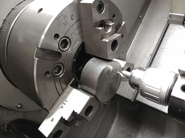
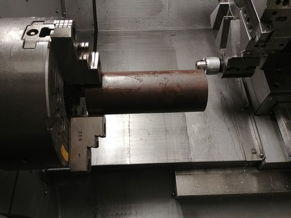
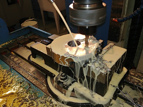
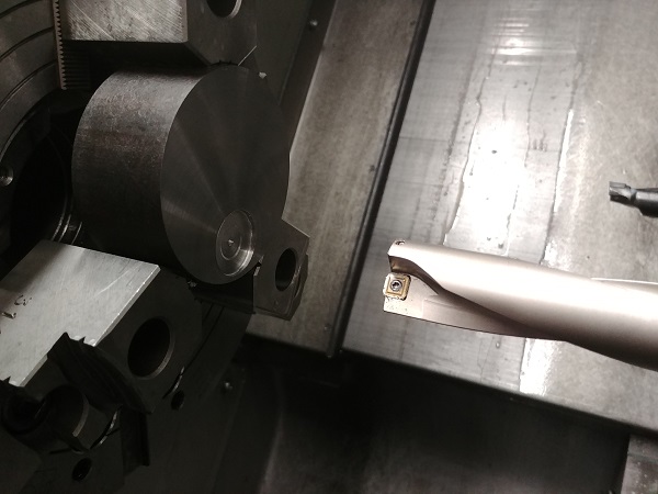
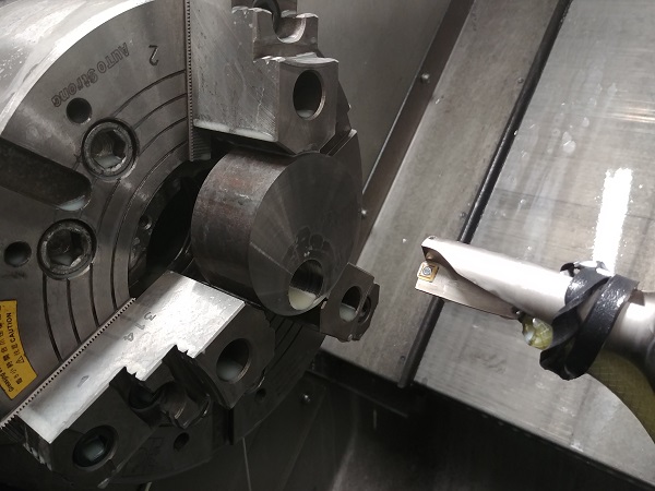
I faced the piece off and bored it out with a 1 inch U-drill. I then used a boring bar to turn the taper profile, this took a few calculations as this holder would have to coincide with a certain point on the rod to that of the jig.
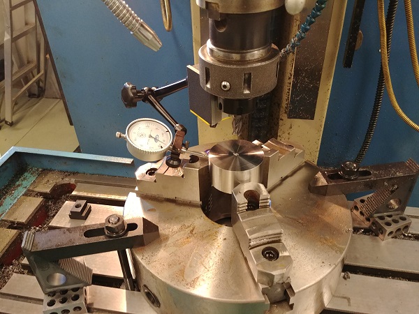
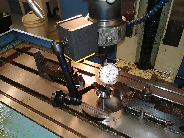
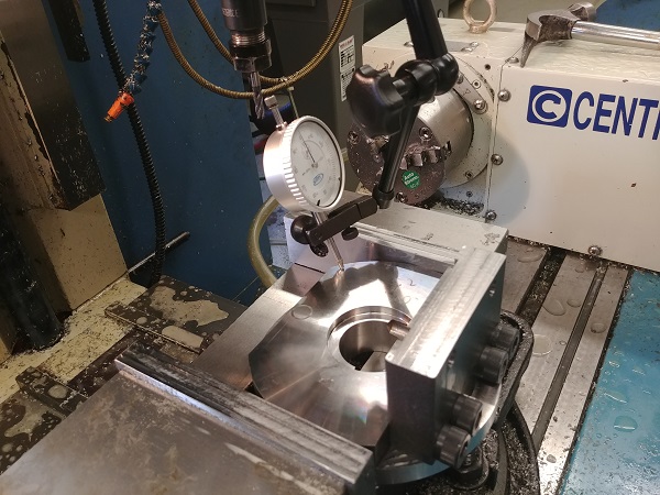
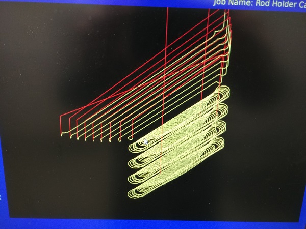
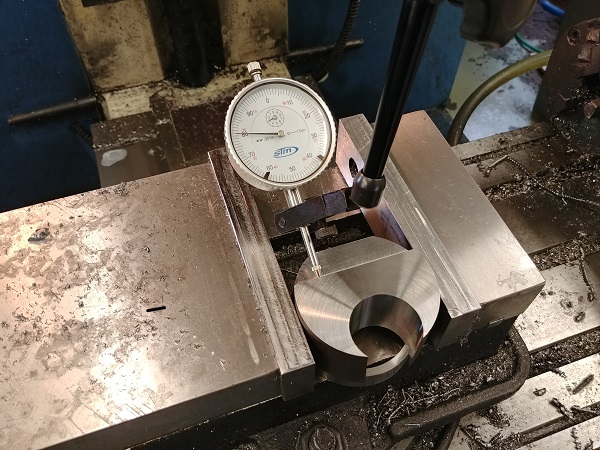
Here it is back in the mill. I used CAM software to generate the tool path, the zero-point the centre of the bore. I used the clock to dial it in, I would have to trust the mill to machine the rest of it accurately.
The mill has a graphic display and a timer to show the tool path.
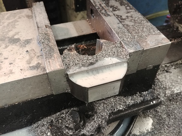
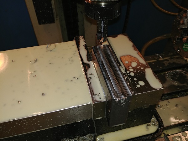
I placed the jig in the milling vise, I paid extra attention in making sure it was flat. I set the mill to the centre and run a slot through the middle, this is where a bolt will lay.
I drilled and tapped two more bolt holes.
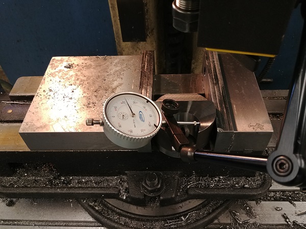
The rod holder was again clocked in the vise.
Two holes were drilled and reamed, these will allow bolts to pass through.
I bolted it together and placed it into the mill vise.
I used an upside down cutter to align it in the slot, they are both the same size. Using the light shining through this method can yield accuracies of one thou, but only if it is very close like this.
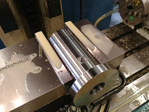
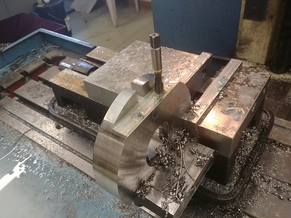
I drilled a hole and tapped it.
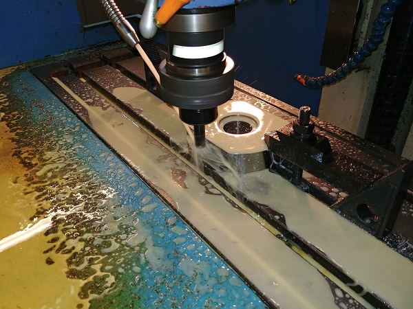
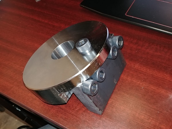
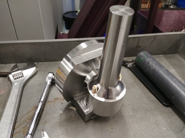
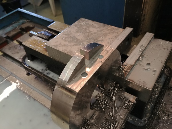
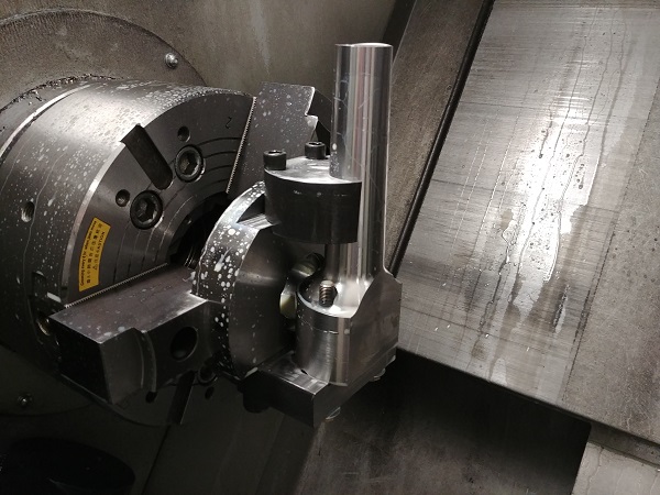
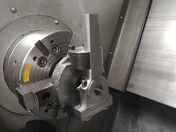
The whole jig was assembled with a rod, it is ready to be machined.
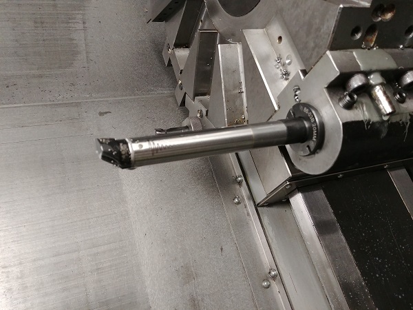
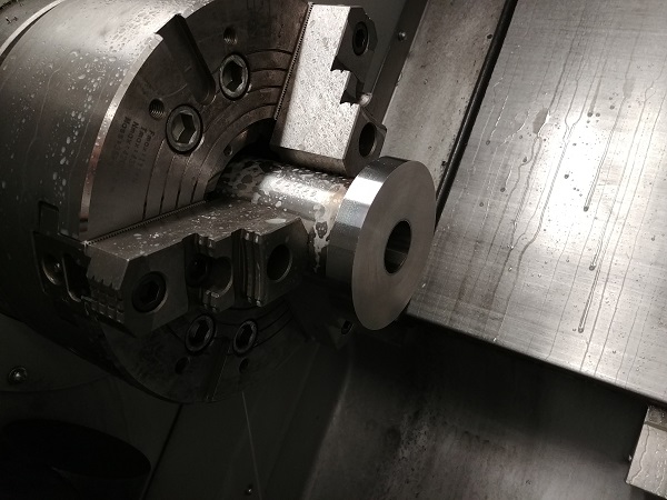
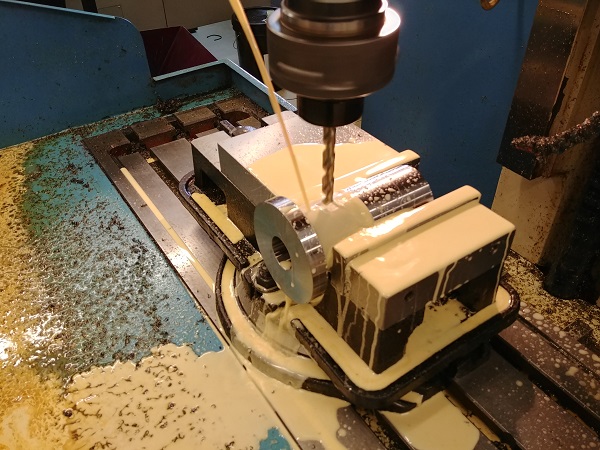
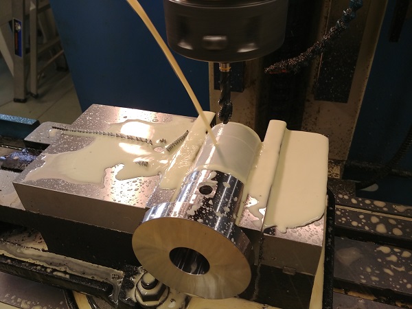
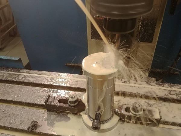
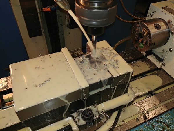
The biggest issue is that this rod is like turning a piece of 14 diameter rod, so it was pretty slow.
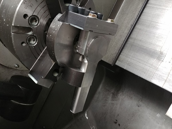
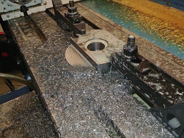
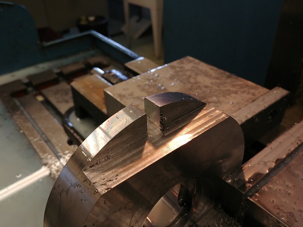
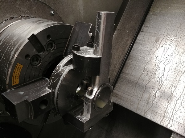
One side complete, it was flipped to do the other.
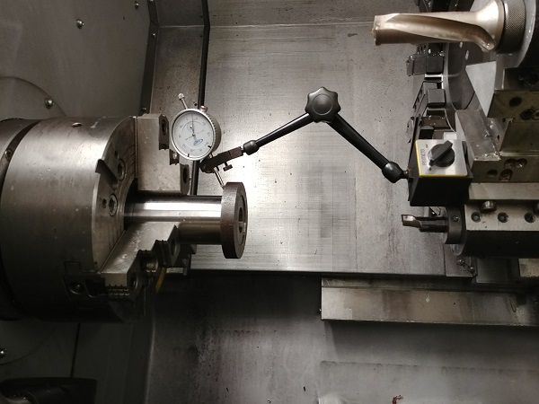
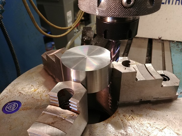
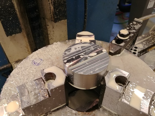
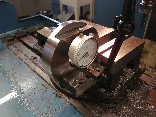
Overall it machined pretty well, slow yes, but doing it in the lathe should ensure the big-end bore is accurate. When I flipped the rod in this jig something did not feel quite right, I could not work out what.
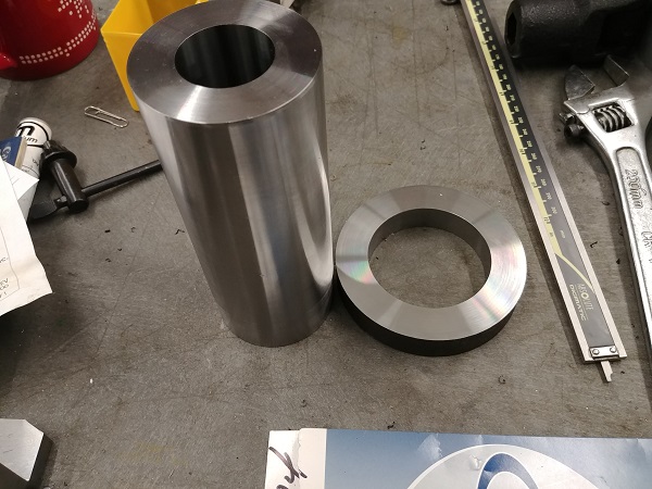
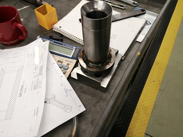
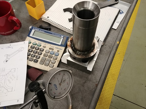
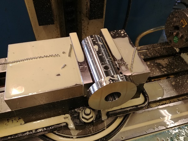
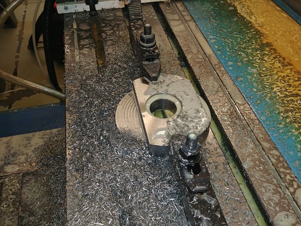
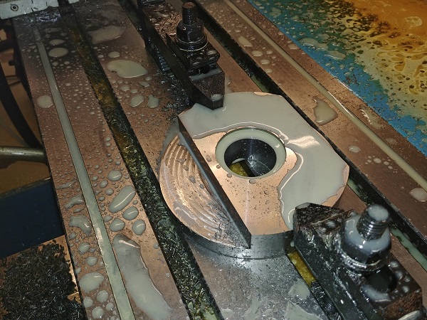
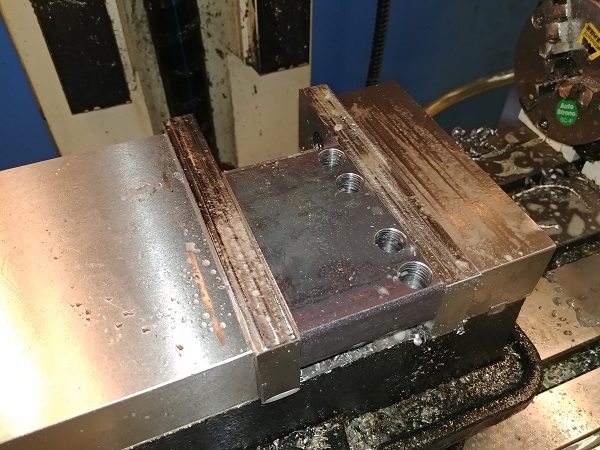
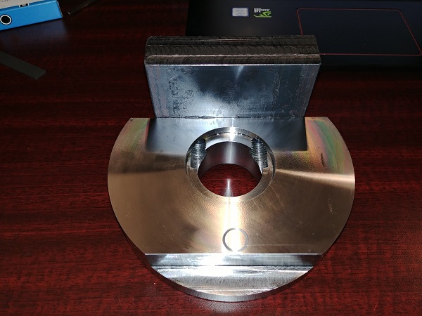
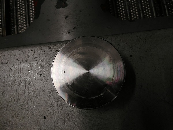
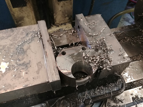
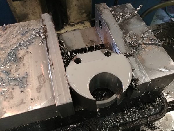
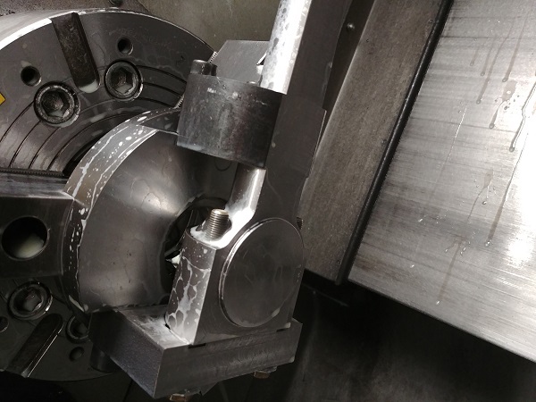
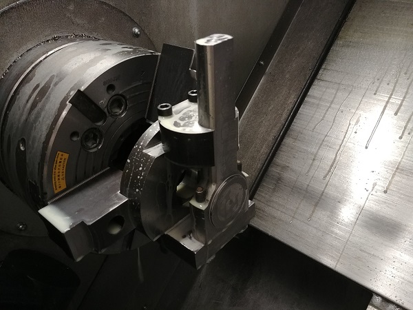
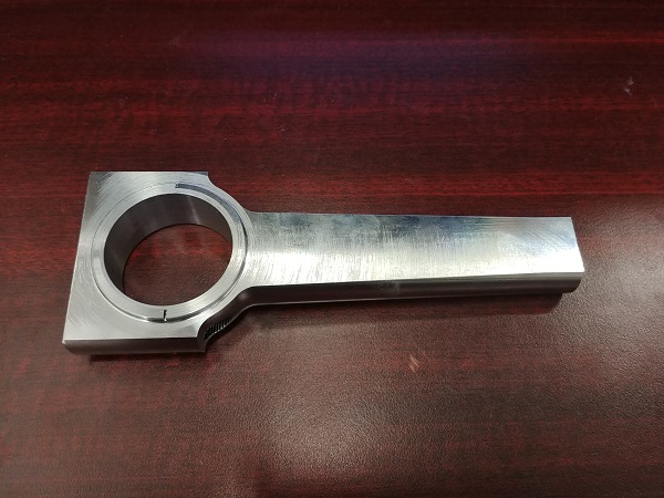
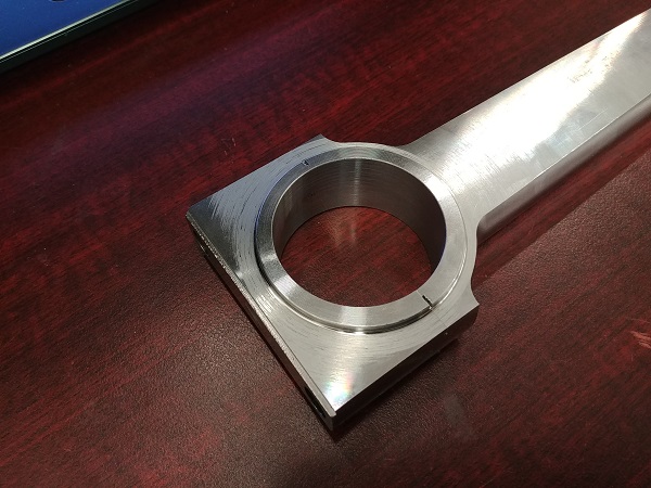
I could see straight away that the bore was offset to the outer. The left picture below shows the first operation, as you can see it looks perfectly aligned. The picture on the right is the second operation, the bore is offset by quite an amount. The confusing thing about the second picture is that all the machining operations were done at the same time, it's as if the rod shifted, I just can't explain why. Apart from this everything measures pretty much perfect.
It has been quite a bit of work up to now, I need these in my engine. So the original plan was to use the lathe because it would have more power and more importantly machine the big-end accurately. Clearly I must be putting some strain on my jig in the wrong areas, afterall there is a lot of force on the bolts. So what is the solution? I'm going to have a bit of a re-think.
I didn't want to use the CNC mill just because it's not powerful, but, it is something I can leave running while I work. The biggest issue with the mill is that it's unlikely to do the big-end bore accurately, I may have to purchase a reamer, a boring head is far too expensive. I think the design of the rod is good, there are a couple of minor changes to make however. Follow the link to the next page for further progress on these rods and the pistons.
Hello, if you have enjoyed reading this project, have taken an interest in another or want me to progress one further then please consider donating or even sponsoring a small amount every month, for more information on why you may like to help me out then follow the sponsor link to the left. Otherwise you can donate any amount with the link below, thank you!