What is inside?
I love to take things apart and enjoy learning how they work. I have taken a huge number of items apart in the past, I think it's quite therapeutic in a sense. I chose to start this page because it allows people to either understand what a unit does and what it is comprised of. A lot of this equipment will be of the medical field, some of it in working condition and some of it not. I will do my best to either point out how it worked, what to look out for when fixing a device or just simply admiring the engineering that went into it, there are some very talented people in this world.
Another thing to note is that some of the units I am unable to test simply because cables and sensors are missing.
Scanning Fluoroscence Detector
28V Power Supply - 24V Battery Charger
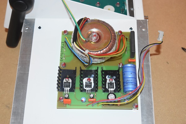
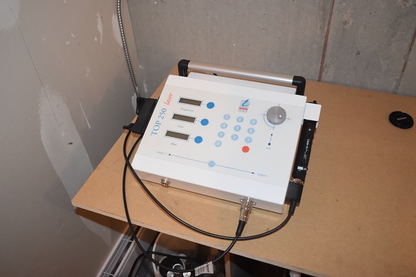
One of the items I acquired was a medical laser, as shown in the picture below. The unit was put for spares and repairs, hence it was free and that was my goal, to work out why it is broken. The model is an Eriel Top Laser which are extremely expensive to buy new but unfortunately it did not have the laser. These lasers are used for physiotherapy or reflexology, they are intended to relieve pain and heal tissue fast.
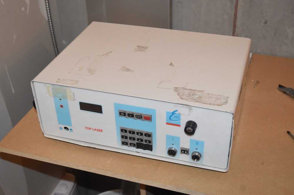
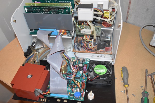
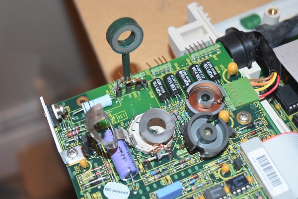
I opened the case to find a very obvious fault, the electrolytic capacitor was stood up on the board. Apart from that I could see a lot of empty space, well considering at the time of writing this the modern unit is $5000 CAD, I would be insulted to have a compact unit.
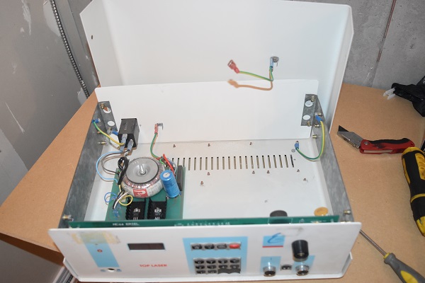
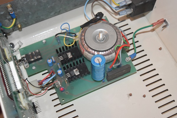
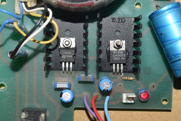
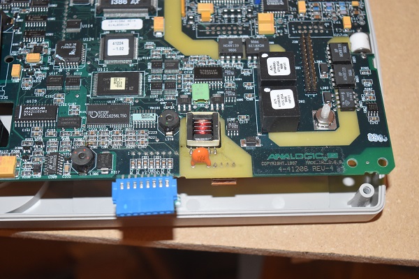
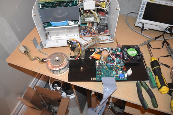
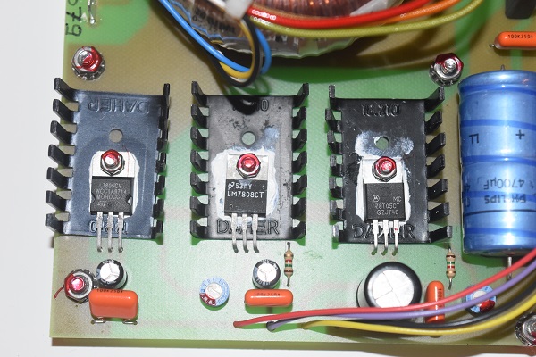
The main voltage (110V AC) is passed through a torroidal transformer, this steps it down to 12 V AC. There are many reasons for using a torroidal transformer such as this, the main one in this case is that it produces very little noise to other components located in the unit. The AC is rectified to DC, this will be around 17V. The voltage is then smoothed via the large blue electrolytic capacitor and then fed into these two voltage regulators. From the part numbers 7805 and 7812 I know that their output voltages are 5V and 12V. These types of regulator are so incredibly common because of their reliability. There are also output filter capacitors after the regulators, 100nF for high frequencies and 10uF for general smoothing.
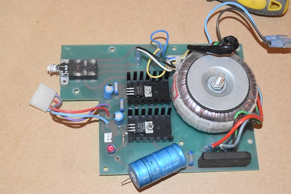
The lead of the capacitor has not broken, what has happened is known as a dry joint. When components are to be soldered they must both be very clean, this is the reason for flux. The parts being soldered must also reach enough heat that the tin wets the metal and forms a bond. A dry joint is caused when there is a weak bond and mechanical stress on the component causes it to come loose. It is very common practise to glue any large components down to a board, for such an expensive piece of equipment such as this it is poor practise. So why would the capacitor cause the unit to fail. Rectified AC to DC has a voltage like a bumpy road, the capacitor is used to smooth the voltage to a constant 17V. Without the capacitor present the voltage drops below the operating voltage of the regulator and therefore causes a loss in power, the unit cannot operate without a constant power source.
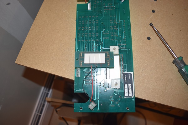
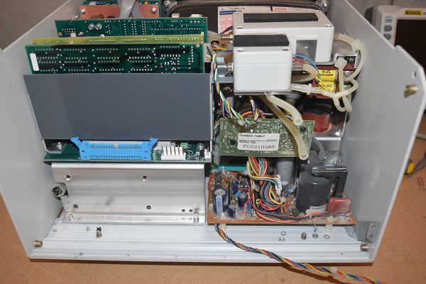
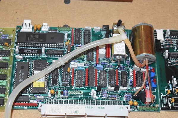
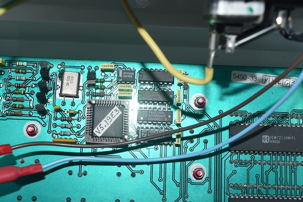
I feel like this unit was one of their very first models. There should never be any flying leads, this is of course a modification, that which I'm not entirely sure of. The points at where the wires are soldered to the board should have at least been covered in hot glue. Whoever did the work also managed to melt a connector, again this could become loose.
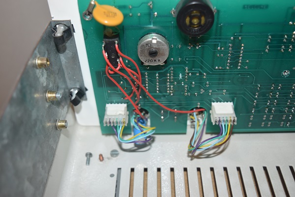
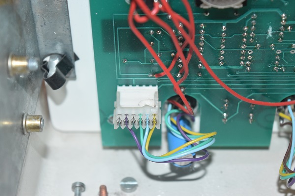
I do know that these units are capable of running two separate lasers, hence the two output sockets. The user presses a button on the front panel in order to swap the power between lasers. I believe there must have been an issue with the power swapping over, I would assume this component is a relay. You can see a large electrolytic capacitor is soldered to one of the sockets, there should be some hot glue to hold this in place.


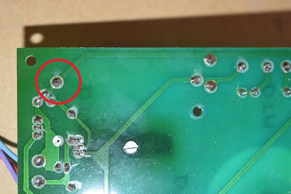
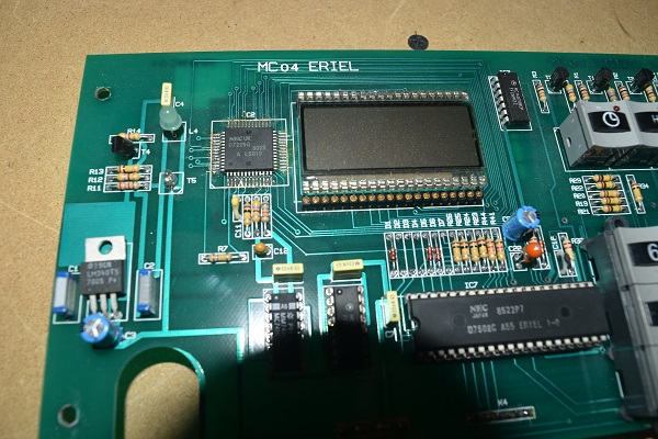
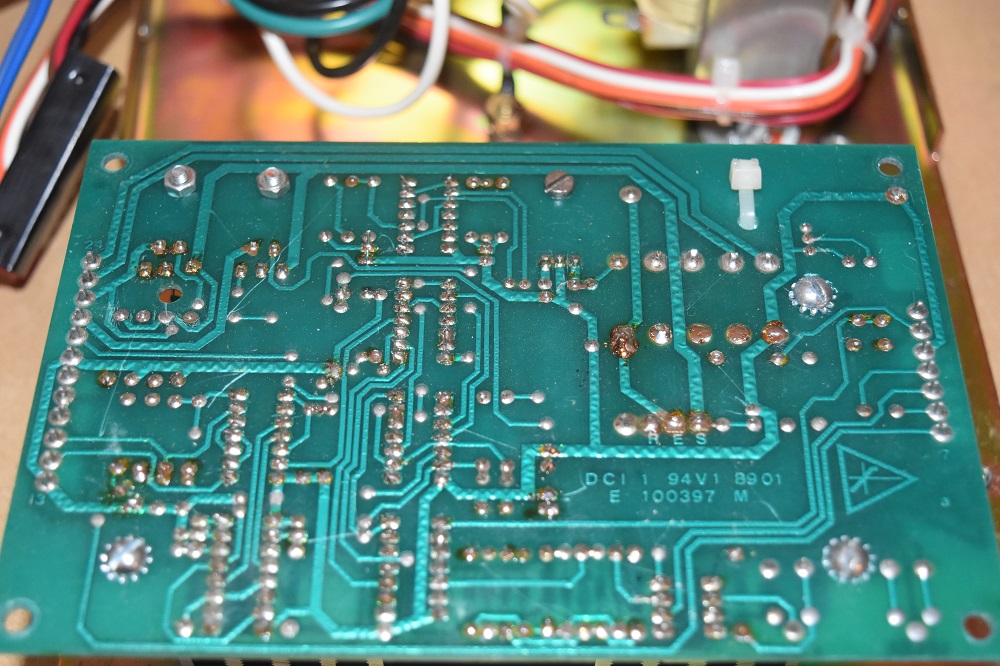
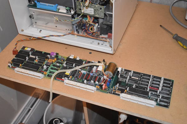
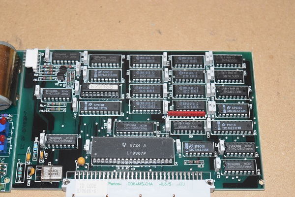
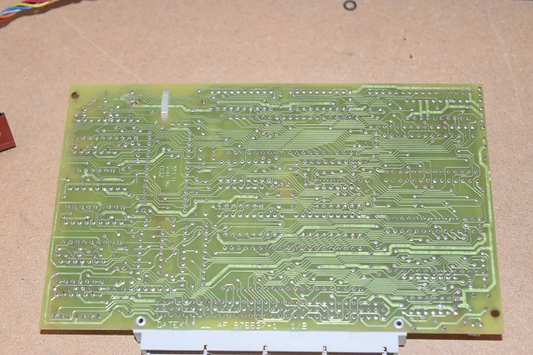
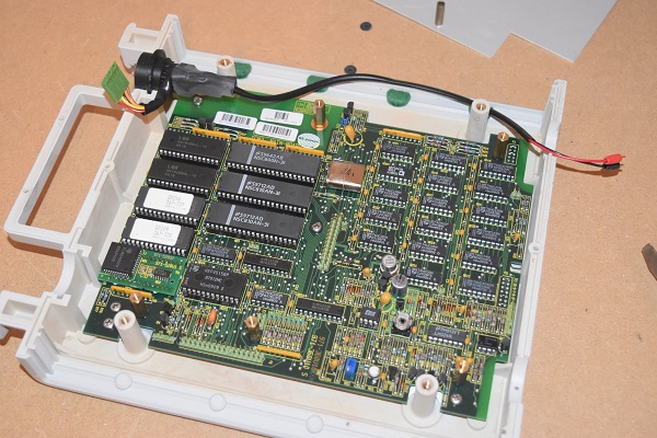
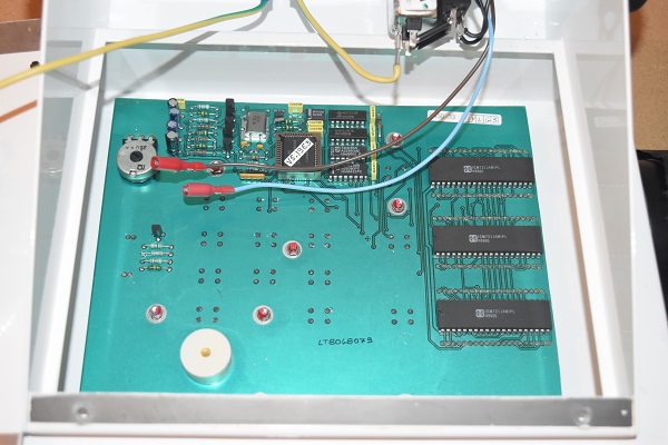
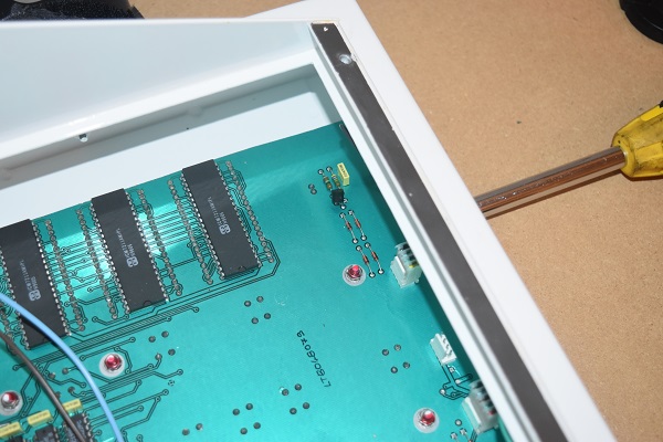
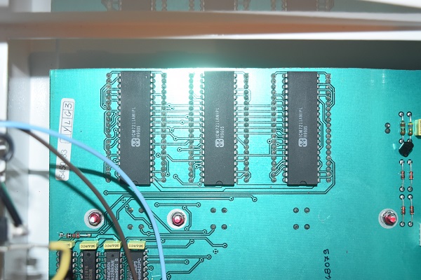
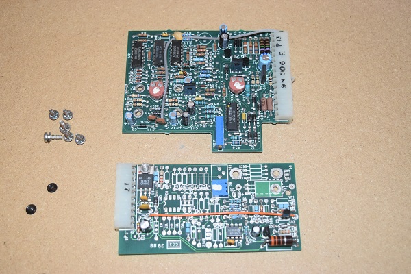
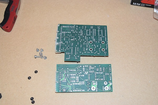
Here is the main control board, in the right picture you can see where the track has been broken to accommodate the modification.
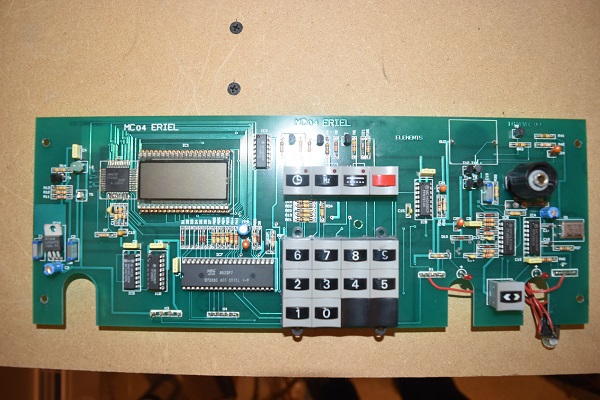
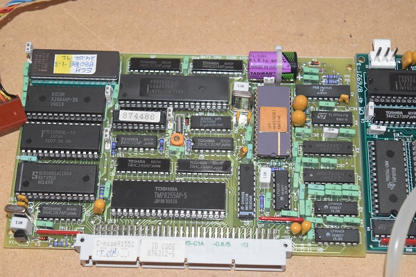
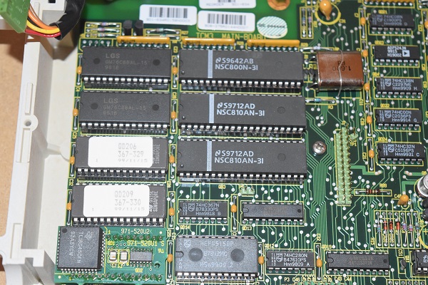
I thought I would look up the part numbers of the chips to understand what their purpose may be. 4046 (PLL with VCO), 4060 (14-stage binary counter), 74LS132N (2-input NAND), 4051 (8 channel analogue multiplexer), 74HC390 (decade counter). The large 40-DIP chip is custom made, I would be unable to find a datasheet, all I can assume is it may be EEPROM or a controller for the display. The benefit to using logic chips is that they are extremely robust, it's very unlikely they would ever fail. The laser allows the user to control the frequency of the pulses, probably the reason for the 4046. The decade counter is used to swap between channels on the analogue multiplexer, the analogue part being feedback from a probe connected to the laser. I can only assume the binary counter is used in setting the oscillator frequency in the 4060 VCO. Of course I could be wrong, it is very difficult to decode a board without the aid of a diagram. I simply don't have the time to manually trace it.
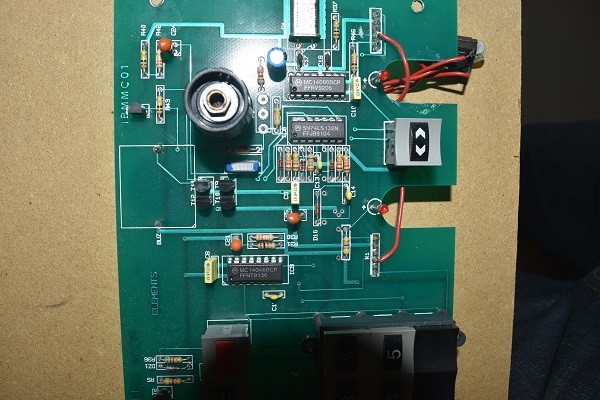
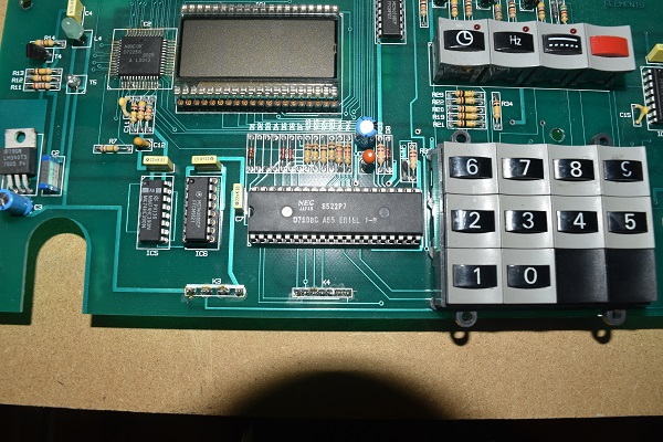
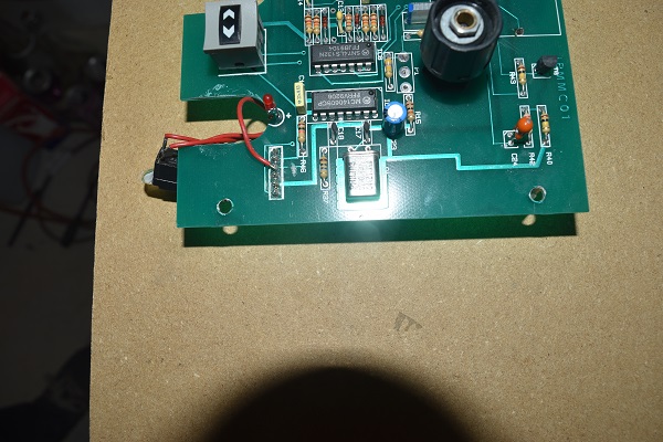
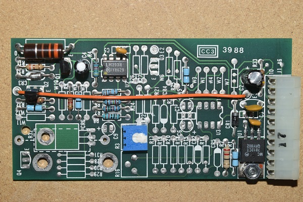
Just above the 40-DIP chip are a series of diodes and resistors, some of these have later been cut out from the design. I would also like to point out that the SMD chip next to the display is likely what controls the board, the soldering has clearly been done by hand, it is fairly poor quality. Something else I find slightly odd is that an LCD has been used that only displays numbers, an LED back light has also been used. What I cannot understand is why the designer did not just use standard 7-seg LED displays.
This piece of equipment is certainly not of the dangerous kind, if it was used incorrectly it is unlikely injury would happen. It just amazes me how many errors there are and design flaws for a piece of equipment that costs so much. The board is certainly not complicated and I feel that the modifications would likely have been made by a service technician, one of the manufacturer. It would have just been a much more professional outcome to redesign and fit a new board.
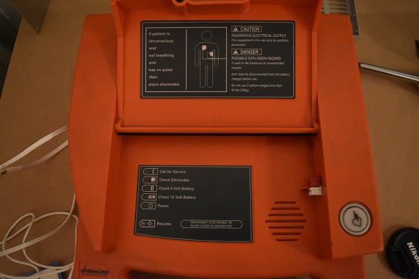
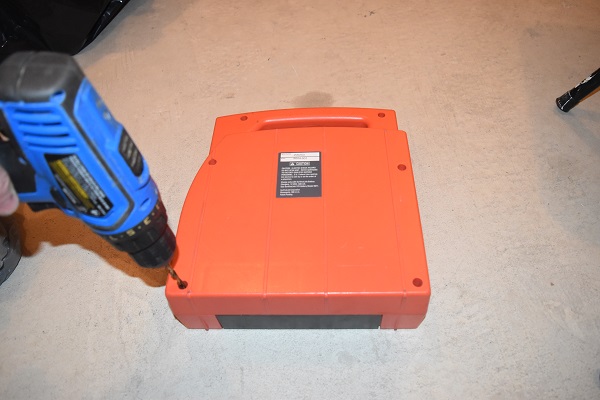
I have to admit that this is one of those strange items, they cannot be sold and really no one needs to own one. This unit looked to be in perfect condition, it would probably work. Since I could not sell the item and I did not want it getting in the wrong hands I chose to take it apart. I would have loved to test it out, but, you only get one chance, so I did not. Well actually it would be impossible to shock myself as these types of units will only work if they detect you're in cardiac arrest.
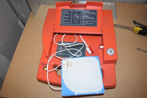
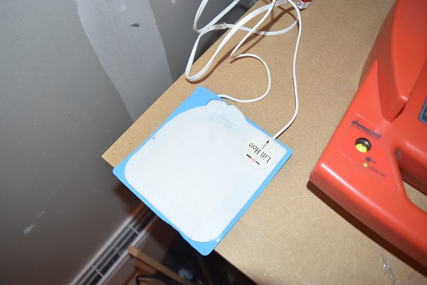
It was actually quite a surreal feeling to hold this unit since the pads had been used, hopefully it saved someones life.
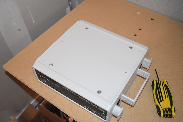
To get to the inside I had to drill out the security screws.
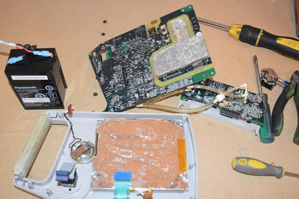
I have never in my life seen so much in one little unit before, I forgot to take a picture but the board below is populated in logic chips. I also did some calculations on how much energy the capacitors stored, 300 Joules. The capacitors are labeled as photo-flash, those are the type found in disposable cameras.
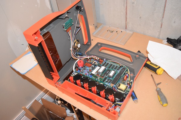
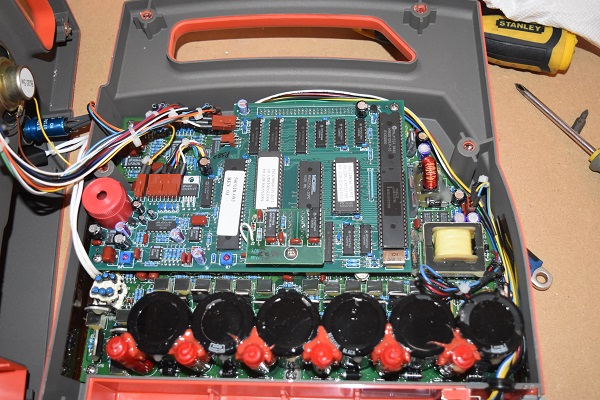
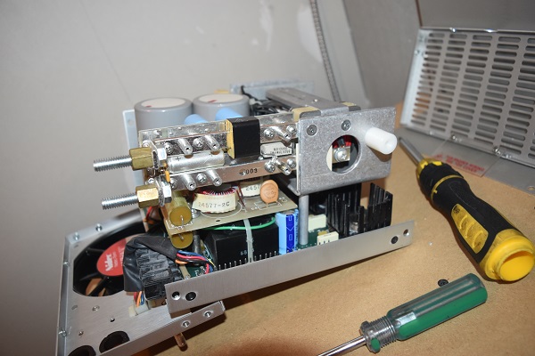
This is probably one of the most complicated pieces of equipment I have ever seen, it would be quite difficult for me to explain it in detail. In basics there is a power supply to the bottom right of the board (yellow transformer), this supply boosts the 9V supply up to around 300V. There are a number of transistors in front of the capacitors which divert the voltage so that they are all charged at the same time in parallel. When the energy is to be released a second set of transistors places all of the capacitors in series to boost the voltage. The red poles next to the capacitors are inductors, these are know as "pulse forming inductors". The purpose of them is to extend the duration of the pulse, or rather they limit the current supplied to the length of a heart beat.
An AED (Automatic External Defibrillator) is an automatic device that anyone can use. This device does a lot more than shock people however. When the pads are placed on the chest it checks for rhythm, it then steps the user through procedures while they perform CPR on the individual. The unit then warns the user to stand clear and shocks the individual, the shock is special in that it passes current one way and then the other. The unit begins to charge again while it asses the individual and instructs the user to perform CPR again. The unit will keep delivering higher power shocks until it achieves a heart rhythm or hits the "x" number of times until it continues no further.
I have no idea what unit this came from, all I do know is that it was used in the medical industry. I do know that the manufacturer specialises in rehabilitation equipment, I can only assume from the dials that it was used for some type of massaging device.
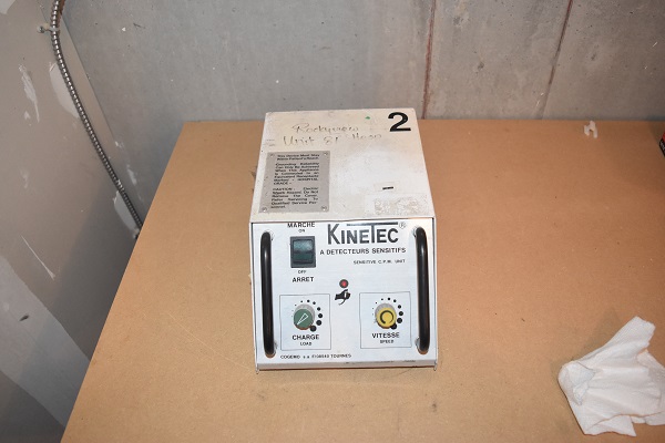
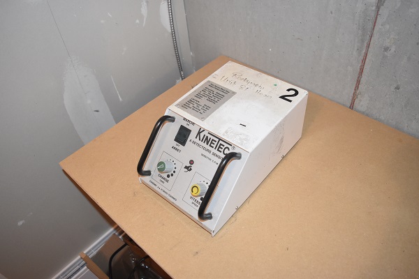
I had no use for it nor was it really worth anything, so I took it apart.
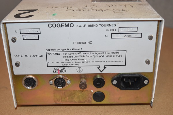
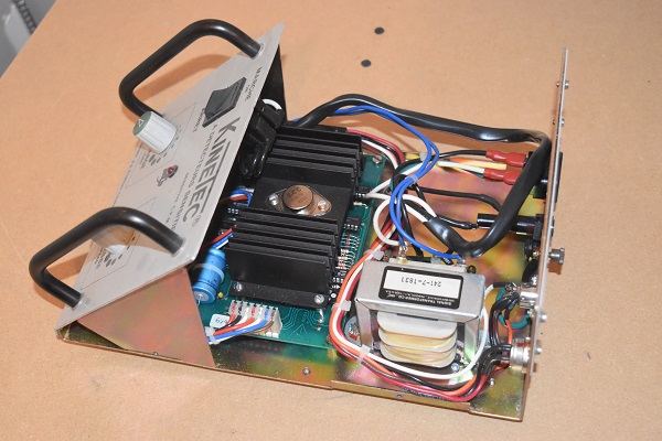
The unit is clearly well built, everything is secured and used the correct connectors. If I were looking for faults on a board like this I would first start with the fuses in the back of the unit, the power switch and then finally seeing if power is present on the board. Some of these old electrolytic capacitors can really last a long time where others sometimes fail spectacularly when powered up. The transistor is the main component in the module as this is what controls the current to the motor, this should be check next.

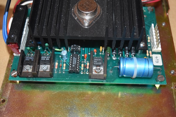
Another thing to check which can be surprisingly time consuming is the continuity of the tracks. On a lot of the older board the tracks tend to go wrinkly, this can be caused by many factors but it is quite commonly humidity. Manufacturers at these times used to leave flux present on the boards, it is an acid. The flux can absorb water, act corrosive and cause current to pass between contacts. It can be as simple as cleaning the board in solvent, once cleaned the continuity of all tracks should be checked. If the unit still does not work after all of these checks then it is simply down to the logic chips, these in most cases cannot be checked without removing the chip and building a circuit from it. I will say that if the circuit diagram is present or you spend a hell of a lot of time tracing the board then you can use an oscilloscope to find the exact issue. A quick example would be to check the drive to the transistor, nothing there, trace it back to the control chip, etc...
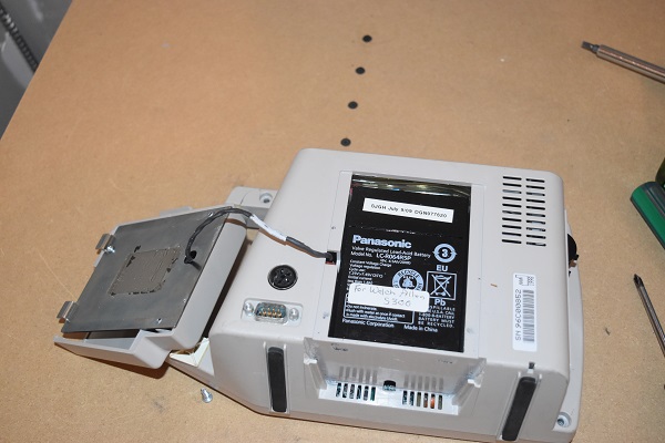
This is another example of a unit that has parts missing, it is likely in perfect working order. So how does a blood pressure monitor work. Blood pressure is measured systolic and diastolic in the measurement of mm/Hg. Systolic is the peak pressure of a heart beat, the pumping cycle. Diastolic is the minimum pressure between two heart beats, this is the filling cycle. The blood pressure monitor fills a cuff with air that is placed around the upper arm on par with the level of the heart. The cuff basically cuts off circulation, it then releases cuff pressure until it detects a faint drop in the blood pressure, this measurement is systolic. The monitor then reads the average pressure between the heart beats which then becomes the diastolic pressure. This method is a fairly inaccurate way of measuring true blood pressure, but it is acceptable if the measurements recorded within a certain range. Those with a fairly high or low blood pressure then have it done manually as this is by far the most accurate method.
Here is a sealed lead acid battery in the back (SLA) which means that the unit is portable. It is normally this battery that determines the life of the meter, generally when the battery stops holding a charge the whole meter is replaced because by that time it will have likely dropped out of warranty.
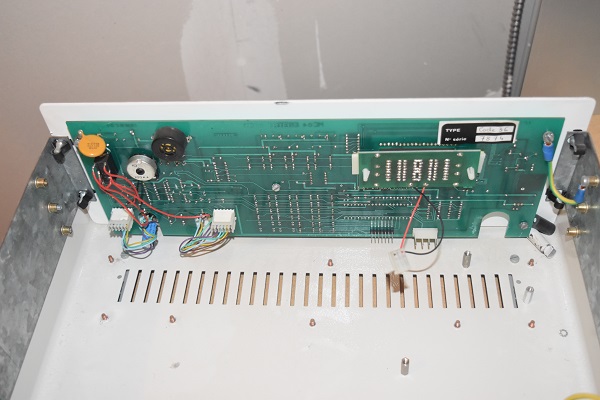
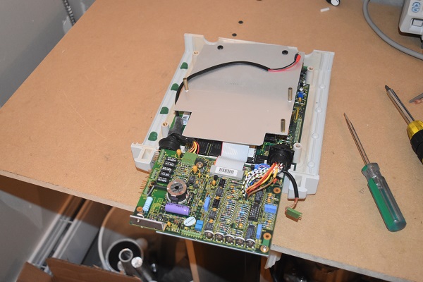
Here is the unit opened up, I can see straight away that there are almost no serviceable components.
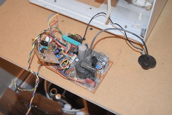
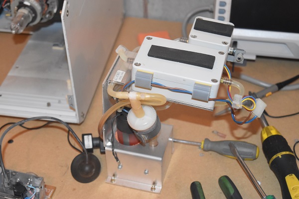
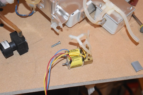
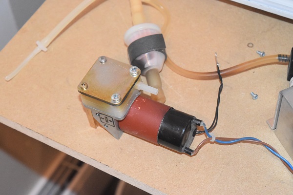
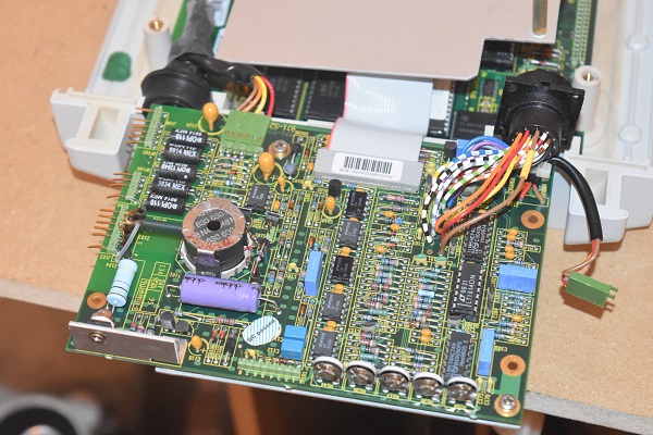
You can see there is a clear barrier between two halves of the board, this must be to help isolate the main boards to those that can be connected to externally. There is a small electric pump that probably produces a pressure in the order of around 1psi, two pressure transducers to accurately measure pressure and a small solenoid valve that is used to release the pressure.
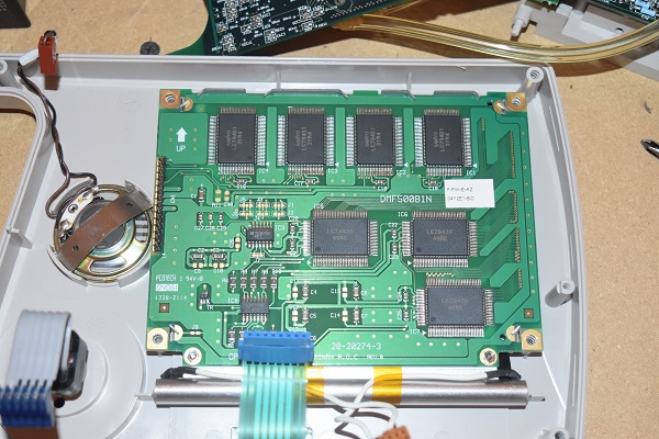
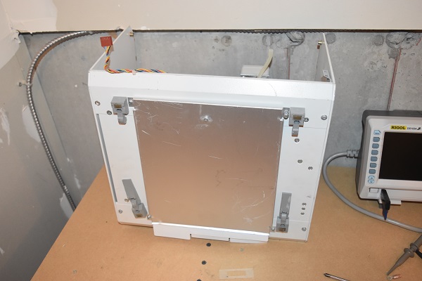
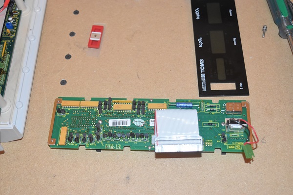
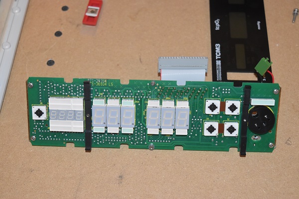
The main reason that I wanted this unit is because of the screen. This screen has a total of fourteen control pins which is very similar to the standard displays I've used in my other projects. It may be unlikely that I will be able to find a data sheet but scavenging this display could potentially save me a little money. The only thing I don't like is that it uses a fluorescent tube as the back light, that requires a high voltage driver which I don't believe I can scavenge from the existing board.
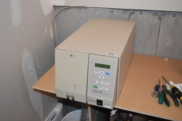
Scanning Fluoroscence Detector
This is a Waters 470 Scanning Fluoroscence detector which in used for spectrofluorometric analysis. So what is it really, well it's a type of spectrometer. It uses a very powerful UV light to excite atoms in a quartz sample tube, these atoms hit a kind of resonant state like illuminescence. When the the light source is removed the atom reverts back to it's original state while emitting photons. The photons travel to a photomultiplier tube. The photomultiplier tube is a vacuum tube consisting of a set of dynodes and electrodes. When a photon is passed into the tube it first hits the photo-cathode which causes an electron to emit from it. This electron then passes though the tube colliding with a dynode which has an electrical charge, these further electrons collide with more dynodes and multiply. Depending on how many dynode stages there are depends on how much the current is amplified. The final electrons hit the anode at the end which results in a current being produced, this is then used to determine what the sample is whether it be metal, biological material or organic material.

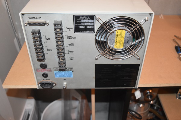
Some outputs on the back for other modules or a computer. The cooling fan is used for the UV light source, it gets pretty hot.
The first step was to start removing panels.
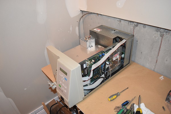
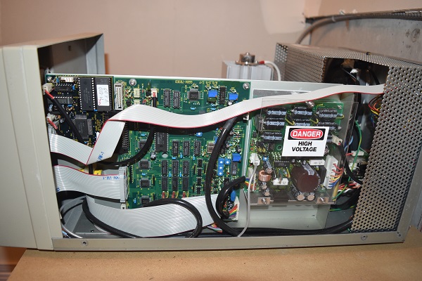
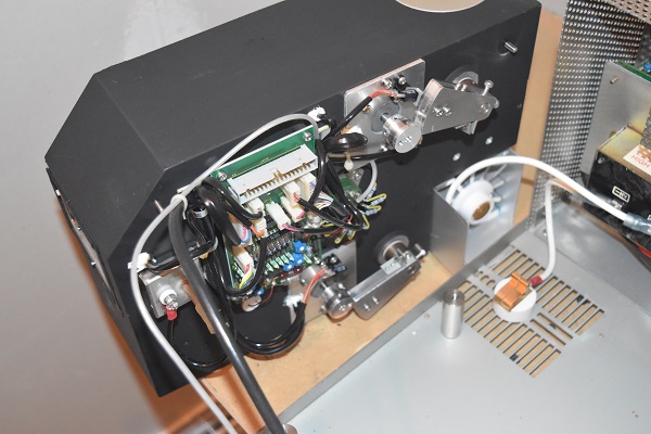
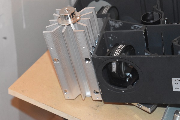
Here is the main control board that will also interpret the current produced by the photomultiplier. This board also controls a series of mirrors and motors inside of the unit. It's hard to see but there is a single sliver wire leading into the high voltage board, this is placed at 2kV for the photomultiplier tube. The picture on the right shows the housing / heat sink for the UV light source. The type of bulb will be an arc-lamp in order to achieve such an intensity, the power supply will fire on the order of several thousand volts to start the arc and then runs on something like 20V to maintain it.
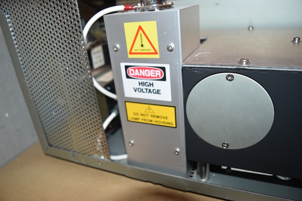
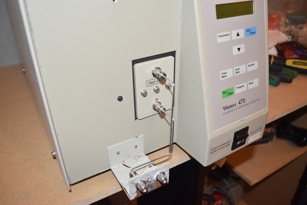
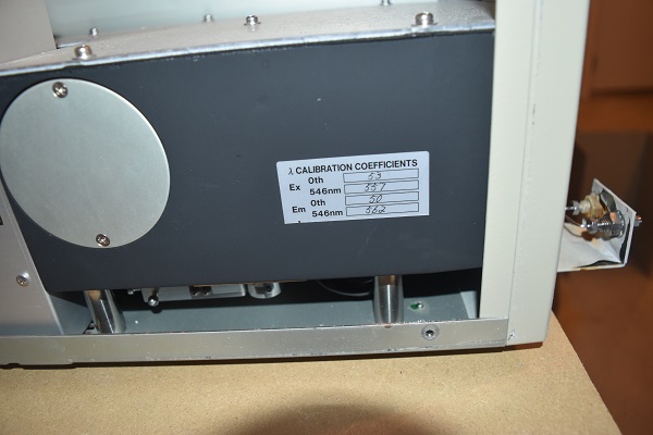
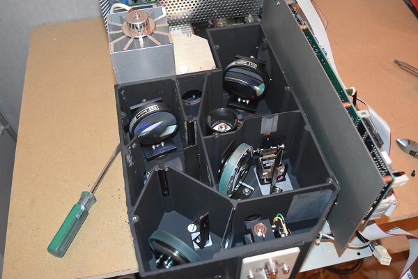
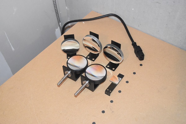
Here is the cavity that will contain the numerous mirrors and the phototube. On the side is an inspection port that is used in the calibration, this is where the technician measures the wavelength of the UV radiation.
On the left side of the cavity is the light source and on the right side of the cavity is the sensor (phototube). These mirrors turn in order to scatter the wavelength in order to achieve illuminescense in the sample vial which can be seen on the right. There are also a series of shutters that allow light to pass, it means the light source and phototube can remain powered to save time. The shutters are simply an on / off that allow light to pass or not.
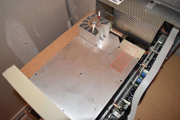
Here on the underneath of the cavity are the motors that turn the mirrors. It is now clear the long silver wire that supplies the photomultiplier tube.
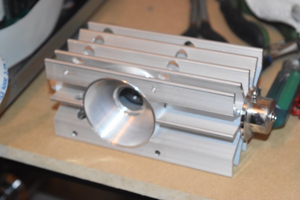
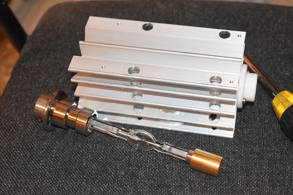
Here is the lamp that is cooled by a rather large heat sink, I will show more detail later on.
Here is more of the underneath of the cavity, note that it is sealed as to not let foreign bodies to enter the cavity.
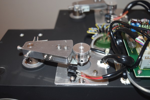
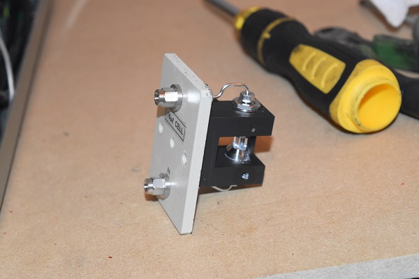
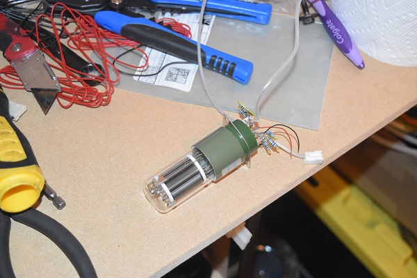
This is something I have never seen before, a film is used to transfer the mechanical movement between the arm and roller. The reason to use this particular setup is because there will be no back-lash as there would be in a belt or gear driven device, this is a very precise instrument after all. Here is the photo tube on the right, it is made by the well-known brand of Hamamatsu, a Japanese manufacturer. In almost all types of instrument the sensors have gone to solid state, this is the one area where phototubes are unparalleled on accuracy and performance.
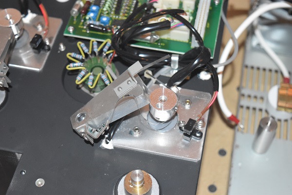
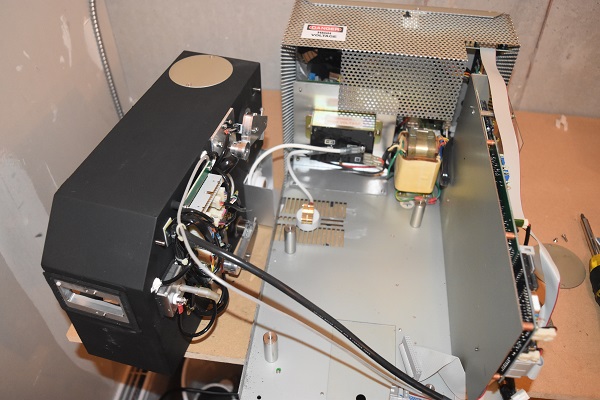
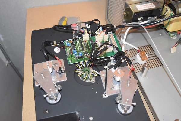
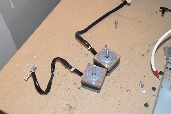
On the left are the two precision stepper motors used for the mirrors, I have never seen such a fine degree of resolution before (0.36 deg per step). In the right picture is the power supply for the UV lamp as well as that for the rest of the unit. There is a switch on the top of the unit which will not allow power unless the case is closed, a safety measure.
The UV power supply on the left and the mirrors taken from the cavity on the right, no idea what I could use these for.

Here is the arc lamp removed from it's housing. I was really hoping that the lamp was a deuterium one so that I could break it inside my nuclear fusor and I would not have to source the gas, check that project out. The code on the lamp is UXL - 150S which means that it is a short arc xenon 150W lamps, runs at 20V. The prices for these lamps are about $500 US, hopefully it might be worth selling. Here you can see in the picture to the right the lamp produces a perfect white light, these are the types used in movie projectors, just on a larger scale.
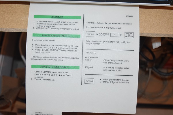
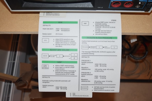
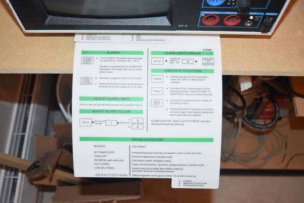
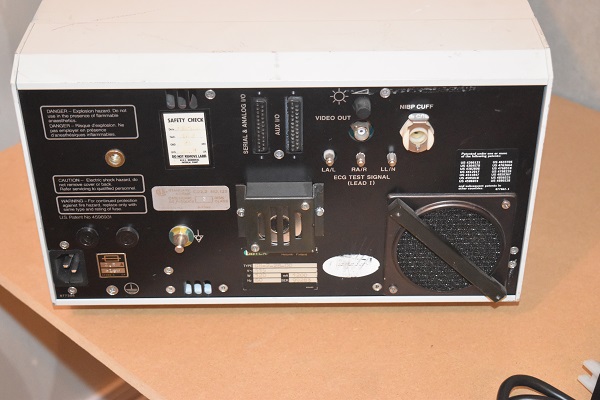
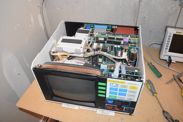
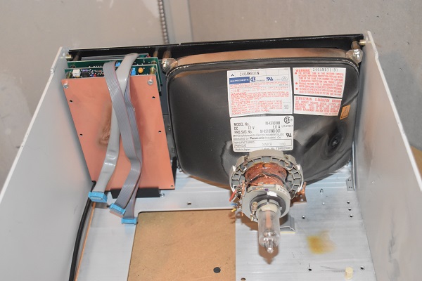
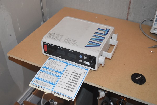
Here is an old CRT style vitals monitor, it was manufactured 1990. Unfortunately I did not have all of the leads to test it out. One thing I really love about the unit is that it even has instructions built in to the bottom.
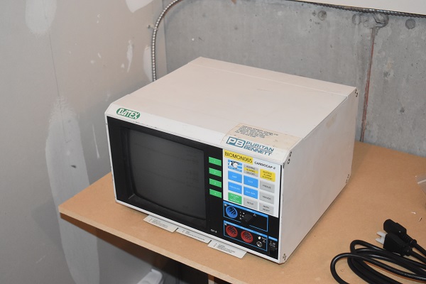
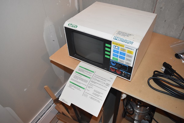
There is so much modern equipment out there that makes little sense or there is never a manual to be found.
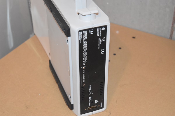
Here is the back of the unit, not much to see apart from the standard serial connector.
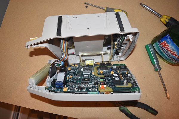
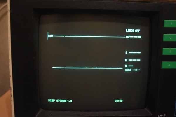
I thought I should take just a quick visual on the inside before powering it up, luckily it was in pristine condition. It also powered up straight away and passed it's own tests. You can faintly see that it has some burns on the screen, these phosphor coated CRT's are very prone to it. A lot of equipment, or what I'm familiar, CNC machines that utilise these screens will have a screen saver or a dark command. Screen saver - stops it from being burnt by displaying a moving image.

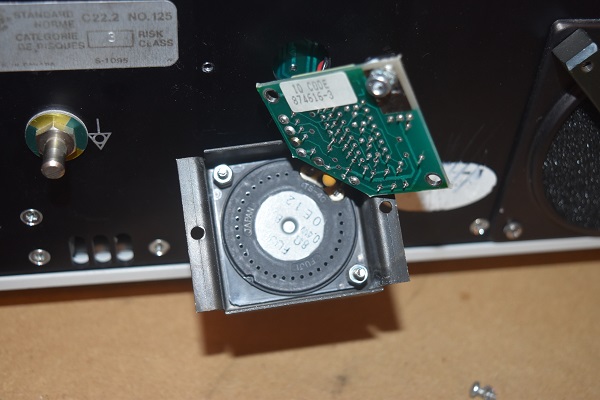
Here is the display that is burnt into the screen. Well it was time to start taking the unit apart. First on the list was a little box on the back of the unit, I originally thought it was a battery. The board consists of a 555 timer and a speaker, I can only assume that this was a warning alarm for a power failure.
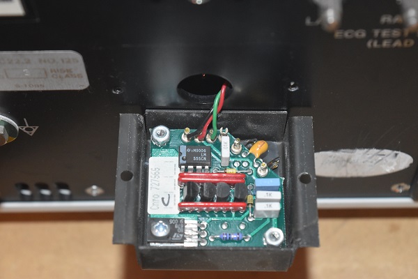
Another view of the module on the back and a view of inside of the unit.
This vitals monitor tracks heart rate, blood pressure and oxygen saturation levels.
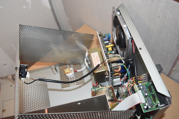
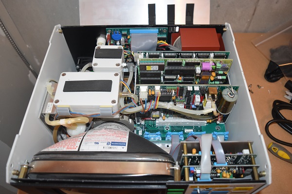
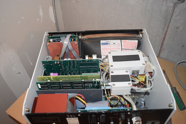
I firstly took the panel off the back to expose the main power supply. If I were to be fixing this unit then this is where I would look first, always check fuses, exploded capacitors and burnt tracks - all obvious forms of a failure. Note that the supply transformer is torroidal in order to produce very little noise, what's more is that it has a steel shielding box on the outside. The awkward thing with this board is that both the power supply and the output circuitry are all integrated together, without a diagram this would be rather awkward to test required voltages.
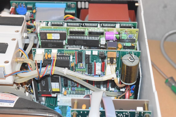
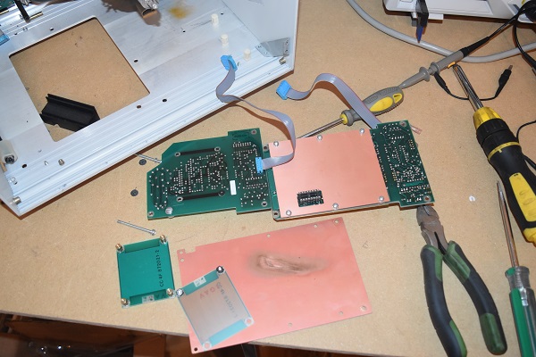
Each of these boards to the left provide a specific function, unfortunately without a diagram I cannot explain that accurately.
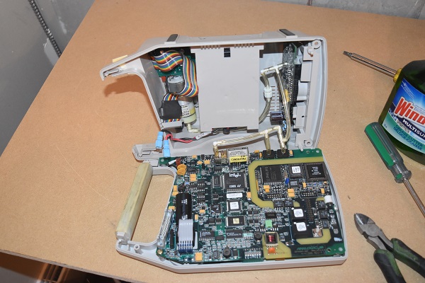
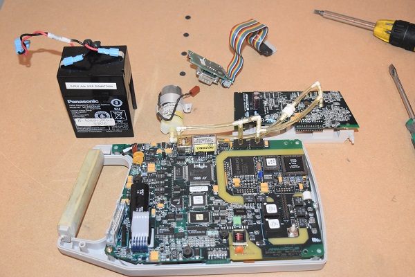
Sometimes to make sense of a board as complex as this it is best to search what each of the components do, unfortunately these are pretty much impossible to service and are replaced instead of fixed. The large DIP-40 retrieves no results but there are quite a few KM4164B-12 chips (RAM) so I can only assume that the board on the left is for the display. The board on the right is to measure oxygen saturation, the sensor is the gold canister. The sensor is an oxygen pump, it will produce a voltage depending on how much oxygen passes through it.
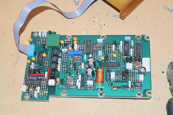
This last board is for the main control of the unit. I can see there are a few different types of chips, analogue since the human body is analogue. There is an EEPROM chip at the top left of the board which will contain all of the settings. The main part of the board is an 80C51 which is an 8-bit microcontroller invented in the 80's, it is still considered in modern designs and is widely available today. There is one chip that I'm a little confused about and that is the one with the gold pad. The chip HADC574ZCCJ is a 12-bit, 20V ADC chip. What I find really strange is that it's rated from -55 to 225 deg C. It is rated for military, aviation, oil and nuclear. Look at the back of the board, that is a serious amount of detail.
I had to take the back off the unit in order to remove the rest of the circuit boards. The next one to remove was the high voltage flyback power supply for the CRT. This is another board to check as there are a few electrolytic capacitors and a couple of transistors.
Some of the pneumatic work.
A pump and the CRT.
Here are some of the boards for the front panel buttons, sockets and switches. There was a lot of copper clad shielding board, there was also what looked like a gold plated piece of shielding. I'm not entirely sure why all the shielding because really there should not be any interference from anywhere else in the unit.

Another one of the control boards for the front panel, a couple of op-amps and some opto-isolators. All I have left is the old CRT monitor, there is no real use for these in the world anymore so I will just dispose of it.

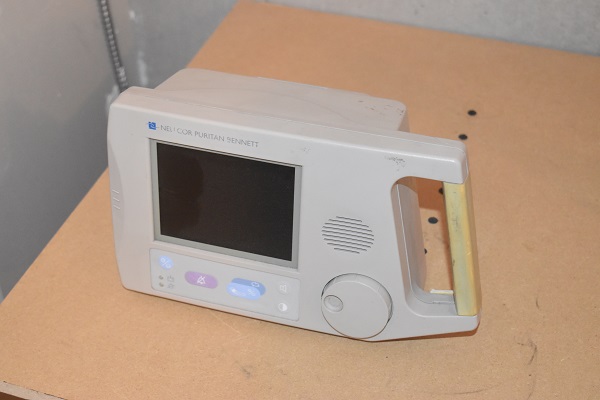
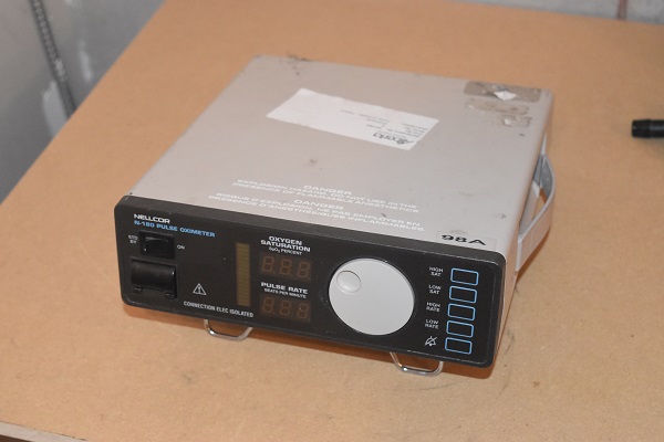
Here is an oxygen and heart rate monitor, slightly more modern. This particular model has the built in instruction sheet. Again I could not test the unit simply because all of the cables were missing.
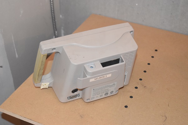
Here is the standardised port for the connections and the power button on the right.
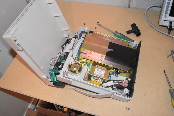
I opened the unit to find that it was battery powered, I guess it makes sense for portability, especially if a patient has to be moved from one room to another. It is clear that this battery is probably intended to last the life of the unit since it's not easily removable.

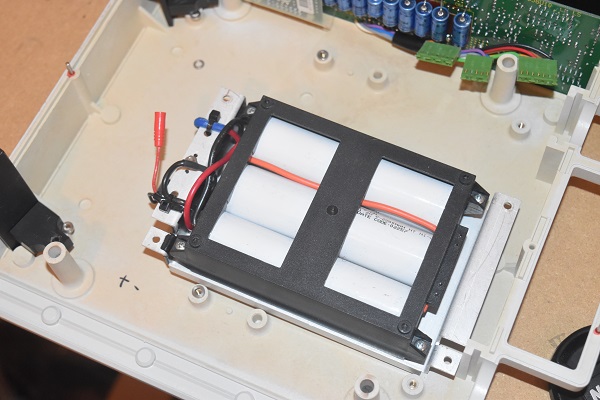
The batteries are nickel-cadmium, the kind you're likely to find in a laptop or drill battery. The reason as to use one of these types instead of a lead acid battery is because they have a much higher energy density and can be more compact.
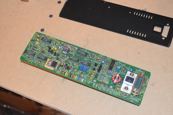
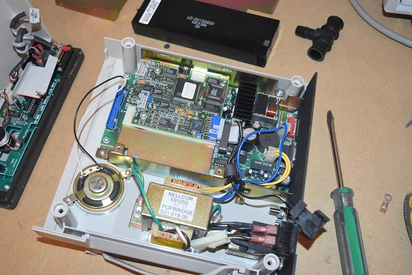
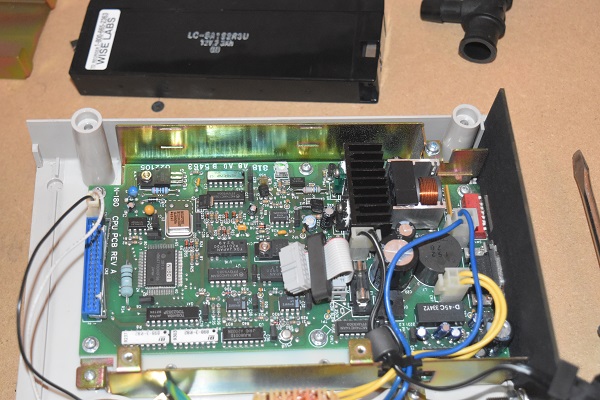
The rear board on the left with serial output and the front panel board on the right.
Not exactly much to look at in this unit, there really are no serviceable parts either.
I was quite surprised to see more logic chips in a newer unit, but I guess they are very reliable.
This is a very modern compact heart rate and oxygen monitor, it does exactly the same as the above.

When these types of units break there really is no point in even trying to fix them.
There is a lot of logic chips used but they are SMD and on a much smaller scale.
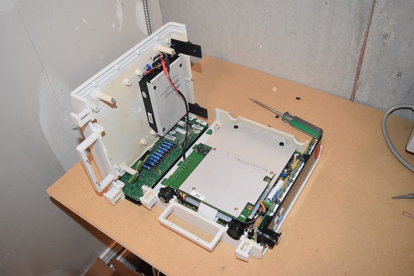
Here is a modern oxygen and heart rate monitor.

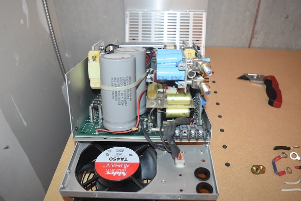
You can see here that there is a lot more spare room, this one has it's own internal power supply and battery charger. I would say that 75% of the room is taken up by the power supply, there is no need to make the unit smaller however.
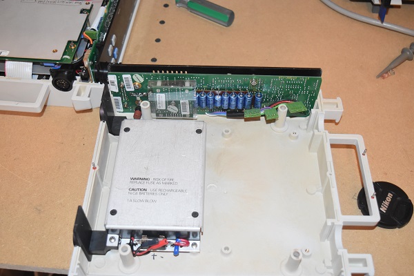
Almost half of the circuit board is for the battery charger. There are a few serviceable components such as transistors, capacitors and a fuse.
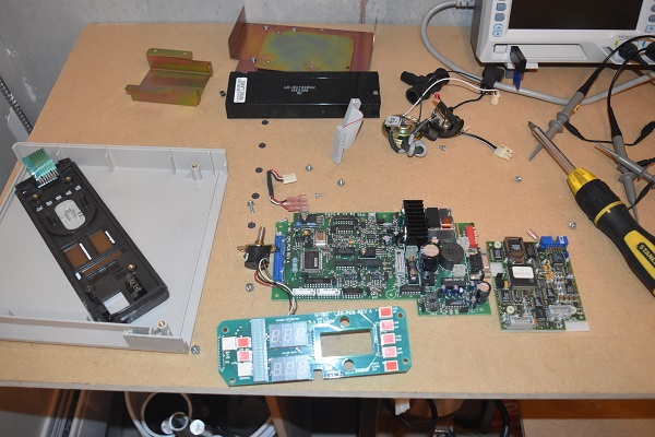
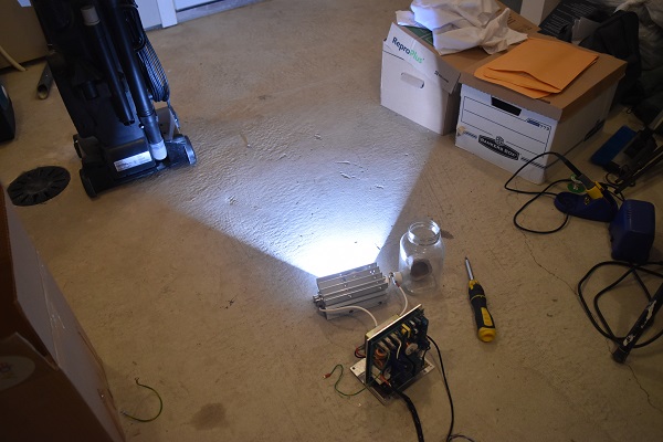
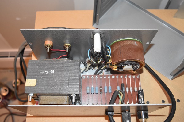
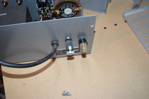
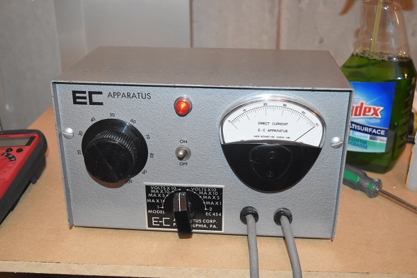
It took me a while to work out what this power supply was for at first. The inside was fairly basic and the output voltage reached almost 600V DC. I thought the "EC" could have stood for "electro-convulsive" but it didn't. After a little research I found that this supply is used for something called electrophoresis. This is where samples of DNA or RNA are placed in a gel, power is passed through which causes it to separate. The macromolecules (RNA and DNA) move in different directions and speeds due to their charge and weight. This is the type of equipment used by forensic scientists to fingerprint DNA.
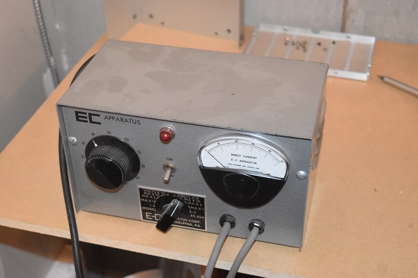
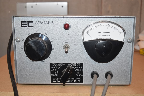
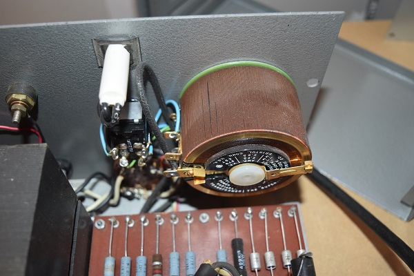
I thought before powering it up I should first asses the condition inside. So here it is, very basic indeed. This is basically a dual power supply, turning the switch anywhere to the left supplies electricity to the left wire. Turning the switch to the right supplies power to the right wire. The incoming supply provides power to a variac, a type of variable auto-transformer. The variac allows an output voltage from zero to 110V AC. Depending on the selector switch will depend which resistor the power is passed through and therefore the current limit, it then passes through a bridge rectifier to convert it to DC. The current is adjusted depending on what the supplied voltage is. The very last position on the switch passes the voltage through this large transformer which boosts it, the rectified voltage is 600 V DC at a current of 0 to 50mA.
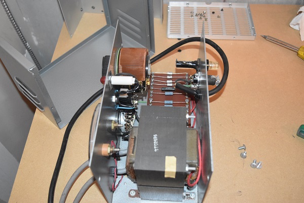
This is such a simple piece of equipment that there is very little to go wrong, it is clearly very old however. It is normally very obvious when a resistor fails because it will have a black deposit, otherwise they are very easy to test with a meter. The bridge rectifier is built from old can style diodes, these are again easy to test with a meter. All of these small components would be very cheap to replace. The variac is the most likely part to fail due to wear, this could simply be the windings in which the whole variac would need to be replaced or it could simply be the carbon brush that is too worn. It is very common for a manufacturer to supply a spare carbon brush.
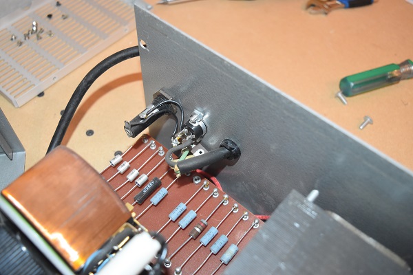
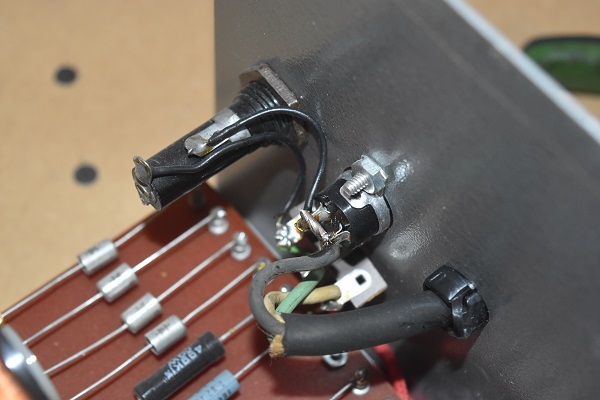
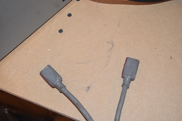
I think this unit would have originally been intended for a foot pedal, this connector however has a bypass soldered in so was never used. Since there is no pedal and the unit won't work without this connector I think it is time to make a little modification.
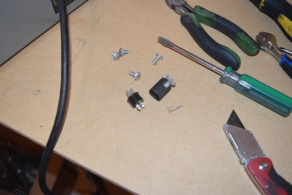
Instead of the connector I chose to solder a jumper wire instead, it is one less thing to loose. I was satisfied that the unit was in perfect condition so powered it up. I tried all of the switches and tested the currents to the best of my ability, it is in perfect working condition.
Just a couple more pictures.
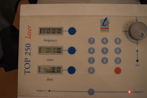
Here is another medical laser. The model is a "Medical Innovation Top 250 Soft Laser" which is used for physiotherapy and to promote tissue healing. I would say that this particular unit is a great find considering that this current model is 2900 euros to buy. I actually didn't think it was really worth anything when I found it so powered it up without checking the internals of the unit. I do have to say that the build quality of this unit is better than the previous, I still think there are too many errors for such an expensive piece of equipment.
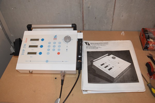

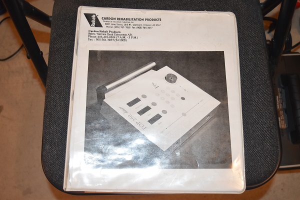
I could not get it to work so had a quick look through the manual, glad I picked that up too. The unit requires a password until you can use it which I found quite comical, the laser is 60mW, that is low power. It looked to be working though.
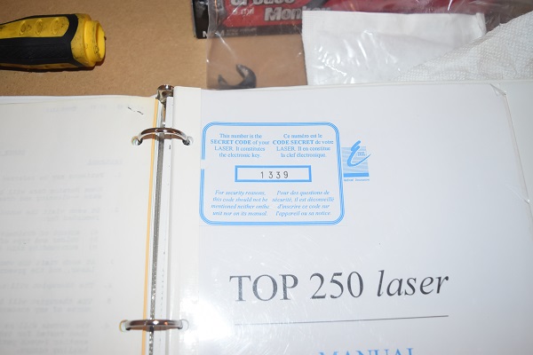
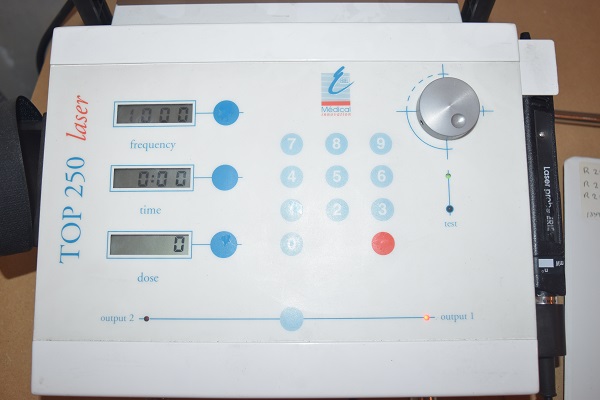
I found that there was a self diagnostic in the manual to test the laser. I have a strange feeling that the self diagnostic is fake since my camera flash also triggered it in another picture, who am I to say. From what I understand the laser is set to a specific pulse time that cannot be changed, depending on the frequency that the laser fires and the time will determine the dose provided.
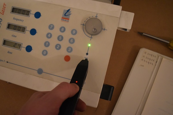
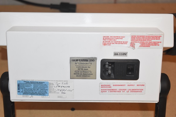
The laser looked to be very dim, but it did pas self diagnostic. I did a little more reading to find the laser was infrared, here you can see it's purple through my camera. The back of the unit with all the inspection stickers and warning labels.

I had already taken a similar unit apart previously, it was time to see if they improved on design. I was pretty disappointed to find they had not, I guess if no-one points it out then they will not know.
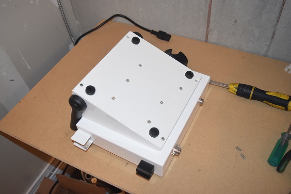
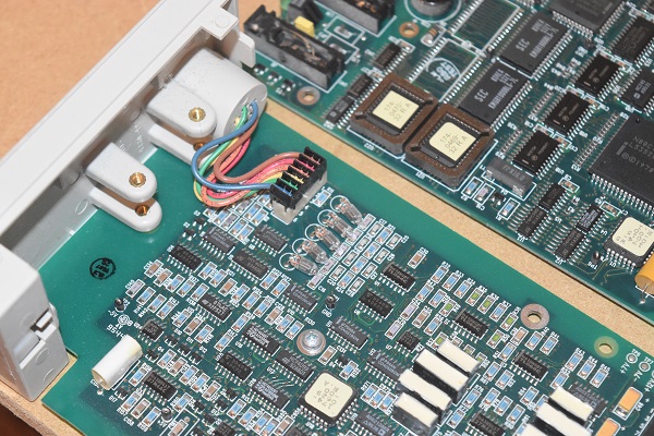
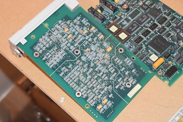
One change is that they have used a thread lock on all of the nuts to ensure they do not come loose, strange when there is a lock washer beneath, it is always better to be cautious however. There is no glue of the capacitor or a cable tie passing through the board, remember this was the failure in the previous unit. A real bad practise is not using something to secure wires, they should not rely on solder alone. In the aviation industry wires cannot be soldered because this is potential for human error if done improperly, wires also wick which makes them rigid and more susceptible to mechanical failure. Wires should be crimped or in this case crimped in a connector and have the correct header on the board.
The board looks to be very professional, no complaints there.
The oscillator for the microcontroller should also be glued down, this could be susceptible to a dry joint.
The manual was certainly very interesting to read through since it gave all of the specifications on what dose should be given depending on skin type, colour and what the level of tissue damage was.
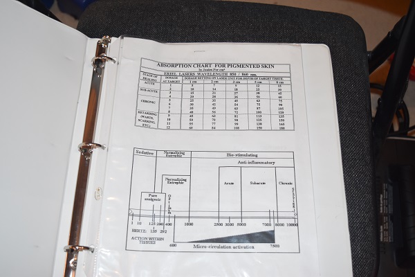
Also in the manual were a load of research papers explaining the technology / theory.


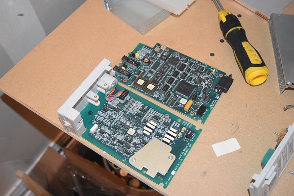
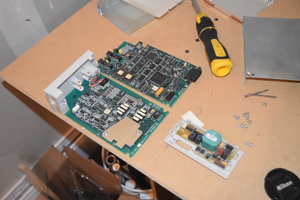
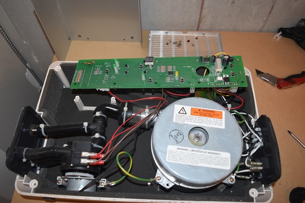
This is the control module and pump for an air bed, this is something I would not be able to sell so chose to take it apart. This particular unit was used to inflate an air mattress, the purpose was to maintain interface pressures for the patient.
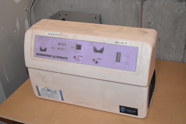
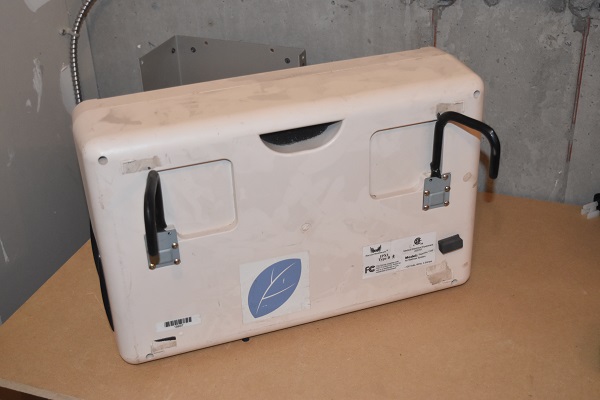
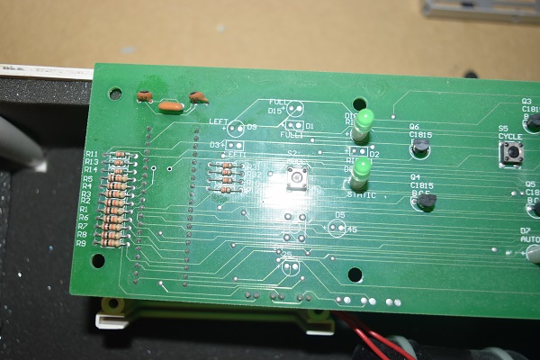
Here it is, a very simple unit. It is padded with foam in order to reduce the noise, this will be running next to a bed for most applications.
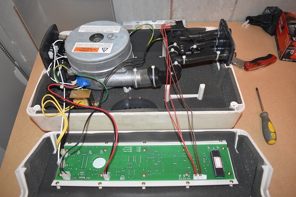
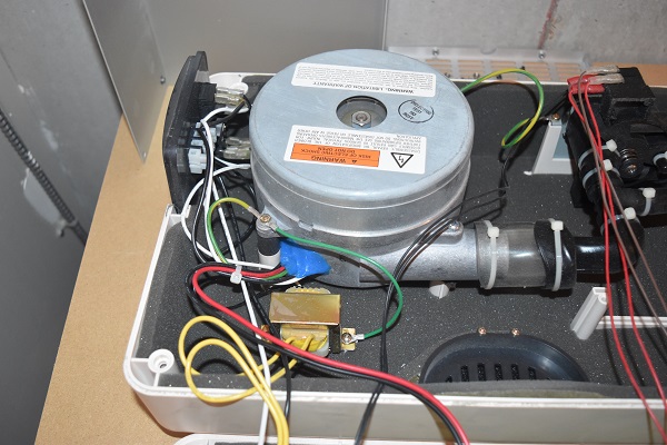
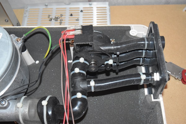
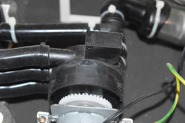
This is the diverter valve which directs pressure to different parts of the mattress. The valve consists of two switches that tell the control what position the valve is at and therefore where it is providing pressure.
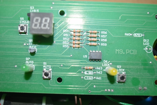
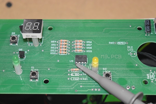
A bar graph display tells the user what speed setting the fan is at, a 7-segment dual display tells the user which cycle it is running if in automatic mode, this would need to be referred to in the manual. Two voltage regulators supply power to the board, one 12V and the other 5V for the microcontroller. A can see that there are some small capacitors missing from the regulators, these should be 100nF to reduce high frequency noise, a mistake I have made in many of my early projects. There is an opto-isolator and triac at the bottom which controls the motor for the valve selector.
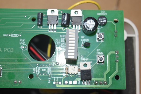
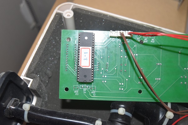
A microcontroller to control the board.
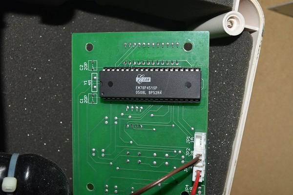
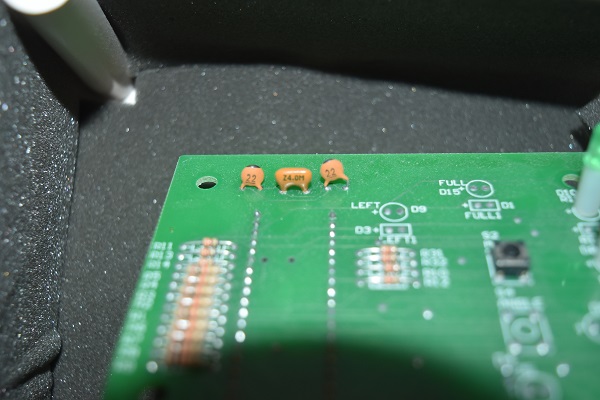
I don't know why I took more pictures but here you can see a resonator and two 22pF capacitors used for the microcontroller clock. The microcontroller is made by a company called Elan, the part number EM78P451SP. It is an 8-bit microcontroller with an extremely basic instruction set, it features SPI, interrupts and a timer.
Something that made me curious was how the blower fan worked since it had four wires.

The first two wires were connected directly to the supply whereas the other two were connected to the output of an op-amp. The part number being HA17358 which is an op-amp rated at 30V at 50mA. The right picture is the valve control, little bumps present so the switches can know the correct location.
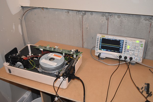
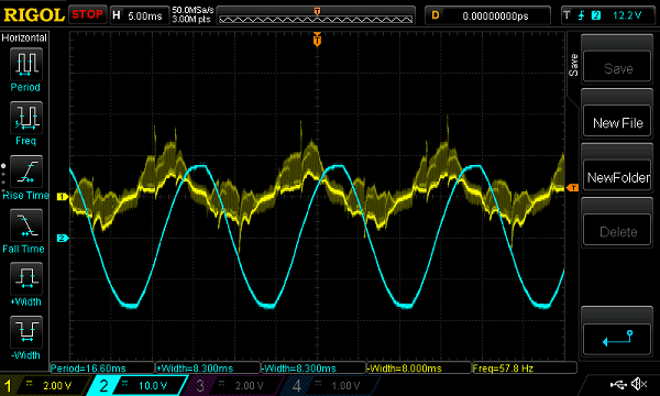
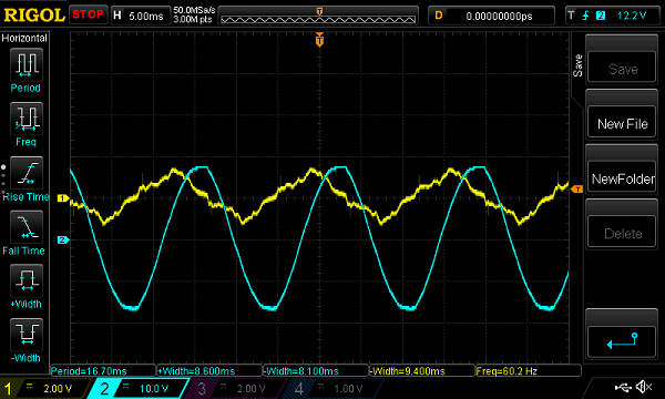
I connected the oscilloscope to the output pin of the op-amp to find that it was providing a second phase for the motor. The blue trace is the 110V supply and the yellow trace is the op-amp, both probes are set at x10. To the left is the motor picking up speed whereas to the right is the motor decelerating.
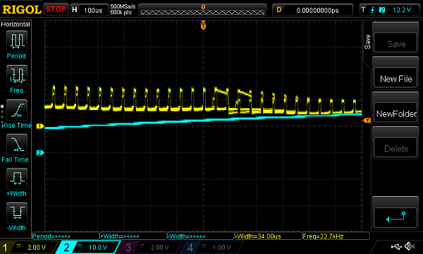
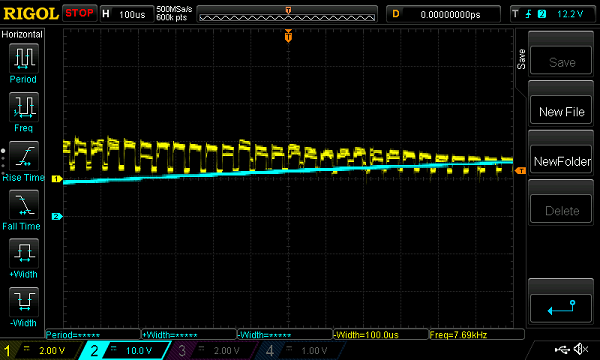
A closer look shows that the voltage is chopped. The trace on the left shows the motor at a slow speed whereas that on the right shows the motor at a high speed. It is clear that the duty of the pulses is great when the motor runs faster. I have to admit that I find this a very strange way to control the speed of a motor but it clearly does work. The other thing is that the op-amp also gives feedback to the microcontroller so it knows what kind of speed it is running at.
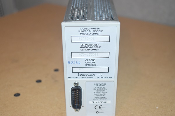
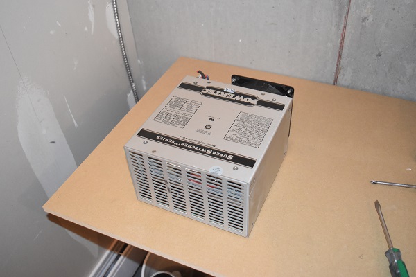
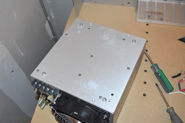
28V Power Supply - 24V Battery Charger
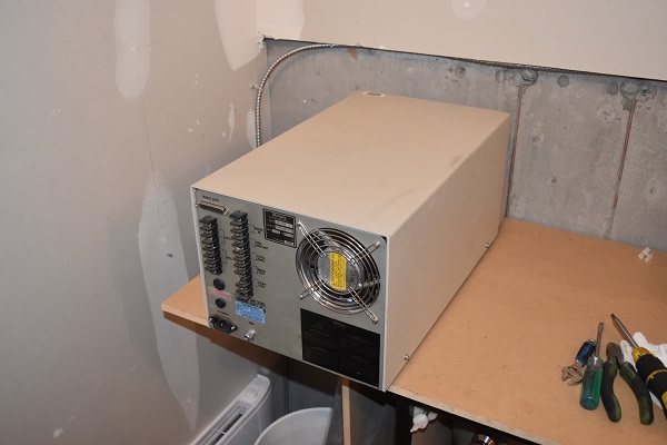
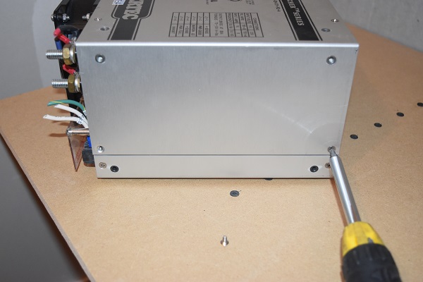
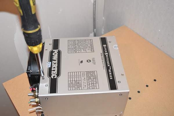
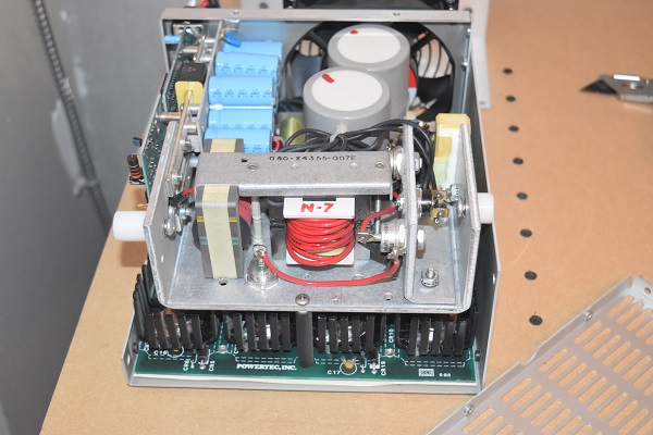
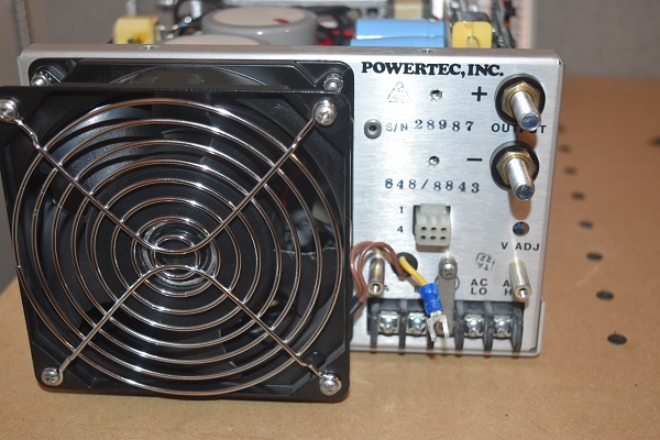
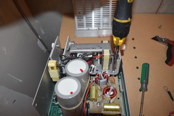
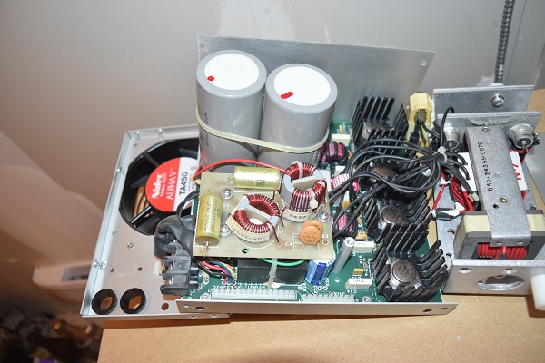
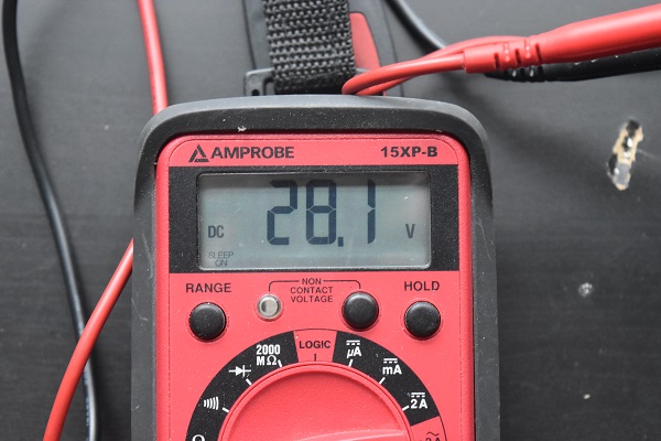
Here is a 28V DC switching power supply intended for the charging of a 24V battery. I did not want to power up the supply before having a look inside.
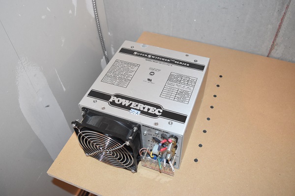
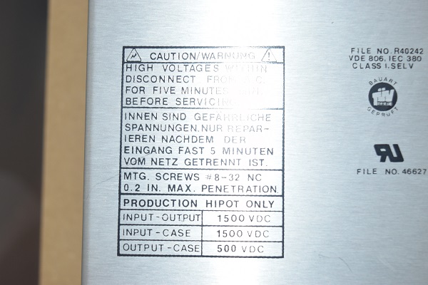
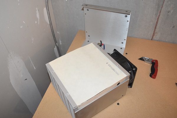
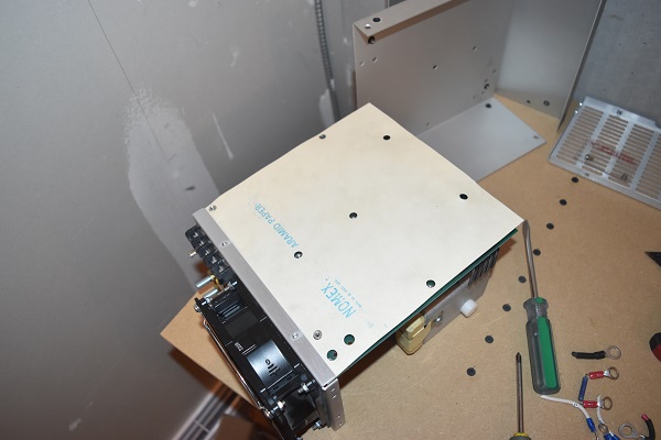
Not long ago it was quite common to see paper insulators inside of power supplies. The paper was often soaked in a resin to stop it from absorbing water and becoming conductive, it is the practise now to use plastic.
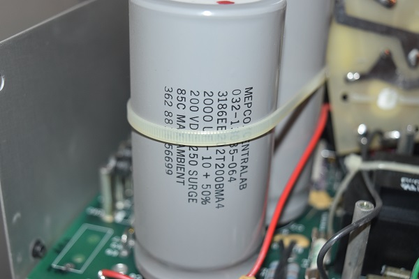
The first step is always to check the tops of capacitors, when they fail it's really obvious as they create a huge mess.

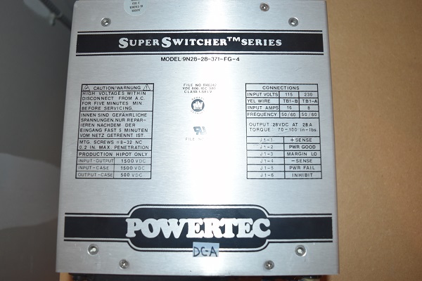
Here is a connection that allows the user to choose between 110 or 220V, it is simply a voltage doubler. When 220V is chosen the voltage doubler is bypassed.
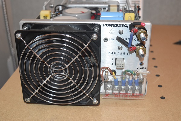
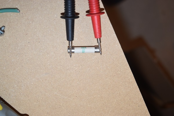
The next thing is to check all fuses, if they are blown then there's a good chance something is wrong.
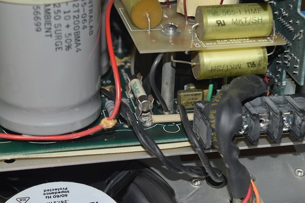
Sometimes it is not clear where all the fuses may be, here is another one hidden behind the filter capacitors. See the black discs next to the filter capacitors, these are thermistors. When these get hot their resistance decreases to almost zero, those can probably flow 15A. The reason to use these is they limit the current to the filter capacitors while they charge, it basically prevents current surges.
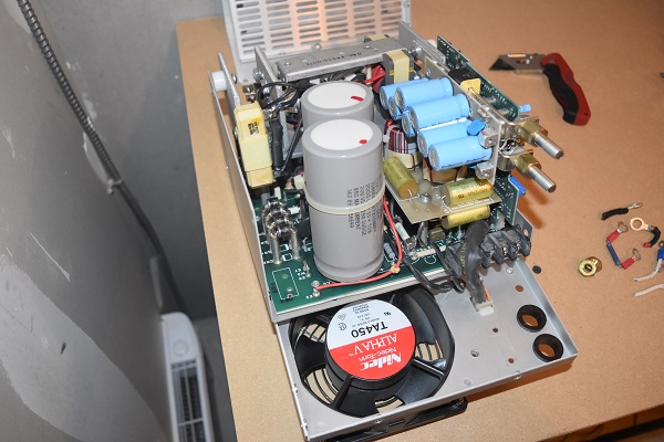
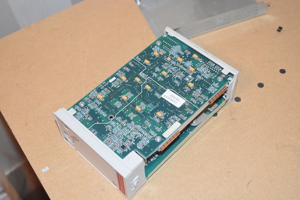
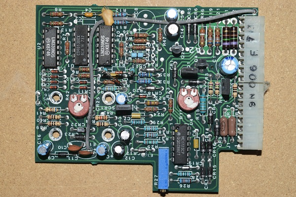
The control boards.
A visual check on these, things like ruptured capacitors, brown resistors, broken traces and even holes in chips. These boards look to be in perfect condition.
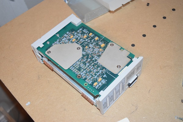
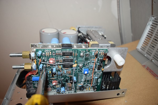
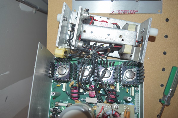
I sometimes like to have an educated guess at what a board may be used for. This one on the left is very basic and consists of a 12V voltage regulator, a comparator and a few transistors. This board will likely hold the rest of the unit in a disabled state until it sees a supply voltage, likewise if power is lost it will shut the whole unit down. The board on the right is a little more intriguing as this will control the switching aspect of the supply. CD4013 is a dual flip flop, LM339 is a quad comparator and the MC1723 is a switching voltage regulator with comparator. I can see that in the main part of the power supply are four power transistors meaning it is likely a H-bridge. A H-bridge is a set of switches that can send power bi-directionally depending on which pair of transistors are switched on (only two at a time). The flip flop will swap between the pairs and the comparators will be there to check if the transistors have switched off before the next ones turn on, otherwise they would conflict and short. The MC1723 allows power to flow until a reference point has been hit, it then turns off. Since the power supply is 28V it means that the reference will also be 28V as set by the blue potentiometer at the bottom of the board. The MC1723 will act as an enable for the flip-flop, it also has a built in oscillator to switch the flip flop, normally around 22kHz as to be inaudible to people. The reason to switch at a higher frequency is that more power can flow through the core, too fast however and it can become inefficient.
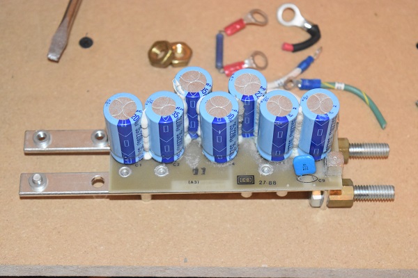
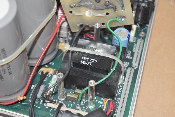
Here is the output circuit, a very large bus bar to cut down on resistance (power loss) and inductance (voltage spikes). The black cube is a ferrite bead that also helps to cut down on transients, high voltage spikes.

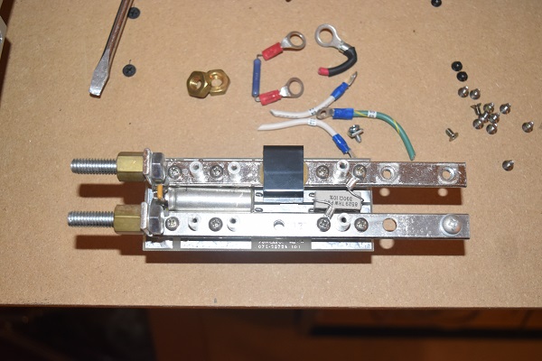
On the bus are a load of filter capacitors, this help to smooth the output voltage, they are also very important as the unit cannot regulate voltage without them. There is a bleed resistor on the bus which discharges the capacitors when powered down.
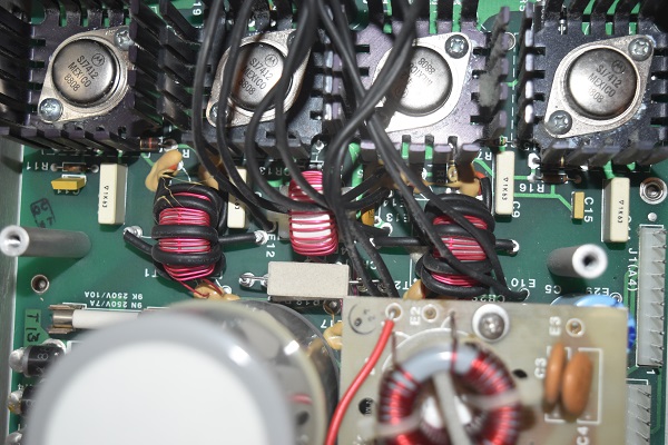
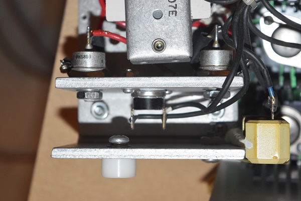
Here is the H-bridge consisting of four power transistors. The top two transistors in the bridge are at a high potential, this causes a problem when trying to switch them on. A transistor has what is known as a base which when current is applied will turn the transistor on. It is quite common for control circuits to run at 12V which when paired with a resistor will provide the correct current to the base. The bottom leg on the transistor is known as the emitter, it is a current between the emitter and base which causes it to switch on. A way of driving a high sided transistor is by using a transformer which isoltates the voltages, the output can go between the base and emitter. The transistor driving transformers are the ferrite torroids to the left and right, the one in the middle is used for current sensing purposes. Since a transformer is being used it means there is inductance and therefore possible transients, the capacitors are known as snubbers which help to safe guard the power transistors.
To the left is a filter circuit which removes transient high voltage spikes from the supply which may damage components. These large electrolytic capacitors are another method to removing transients and provide a smooth consistent current to the power transistors.
Checking a fuse on the left. Here to the right is a low voltage transformer which supplies power to the control circuit. Remember the first control board, that checks to see if this is producing power and holds the power transistors off if not. A transformer can act like an inductor, when current is stopped from it causes a voltage spike, the capacitors at the front of the transformer numb these voltage spikes as not to cause damage to other components.
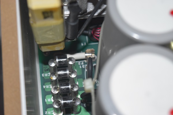
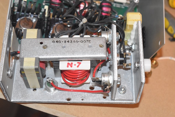
Here is the switching side of the unit, a high frequency transformer. The red wire is the secondary of the transformer which will consists of around ten times the turns of the primary in order to step it down on a magnitude of ten. There are stud type diodes which recifty the AC from the transformer into DC. To the left is another inductor which is known as an impedance matching transformer, this acts like a current limiting device.
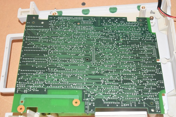
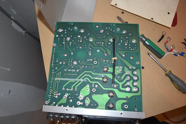
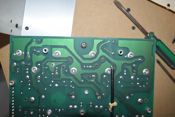
It is a wise idea to check all the traces on the board, hence removing the bottom of the unit.
The traces were in very good condition, it is not unusal to see tracks lifting on the older boards. These power supplies are quite nice because they use servicable components, those are normally capacitors. It is quite unusual to see screw mounted capacitors that are soldered in, they would be quite difficult to remove without a soldering gun.
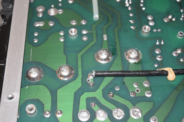
I will say that this unit is one of the best I have seen in terms of construction. All capacitors, inductors and large components are held with a stiff adhesive. The filter capacitors even though screw type are soldered in, the biggest failure I see in power supplies are these types coming loose and causing surges. I would say that the only thing that I dislike about the design is the use of paper, who am I to say, high voltage capacitors used to use paper (and oil). I did want to show some waveforms of how the power supply worked but I had nothing to load the supply so could not.
I think that is it for this page, I hope you found looking inside some of these items as interesting as I did.
Hello, if you have enjoyed reading this project, have taken an interest in another or want me to progress one further then please consider donating or even sponsoring a small amount every month, for more information on why you may like to help me out then follow the sponsor link to the left. Otherwise you can donate any amount with the link below, thank you!