ECU User Display Interface - Page 1
My current project car is a 1998 Hyundai Tiburon. In the near future I plan on doing some performance modifications to my car such as a turbo, in the process of doing this I will need an ECU since the stock one cannot be programmed. This project is about making a user interface that will link to other modules such as the ECU, the AFR meter, etc...
06 August 2017 - I started this project back in April but it is only up until now that I'm typing it up. The first step was deciding how it was going to work, I quickly thought that it should control four auxiliary relays and talk to the master ECU via SPI (Serial). The interface would be a 264 x 64 pixel OLED display with a button array. The board would contain several memory chips, one for the display and the other two as configuration settings for the ECU.
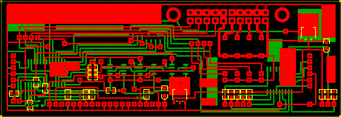
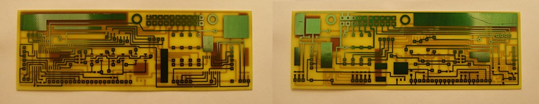
After several hours of design I finally came up with a dual layer PCB file. The board contains two 18 Series Microchip microcontrollers, one for the button array and a master chip to control the whole module, capable of running at 64MHz. I utilised as many surface mount components as I could to save on drilling holes.
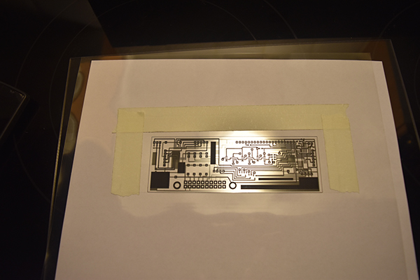
Both sides of the board are printed onto two sheets of transparency film, they are then taped together and the photo sensitive board is placed between them. Each side of the board is exposed to a light for 8 minutes in order to impress the design to the special coating.
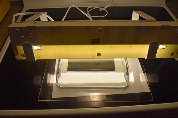
The board is then placed in developer, the tracks remain with a resistant etch coating.
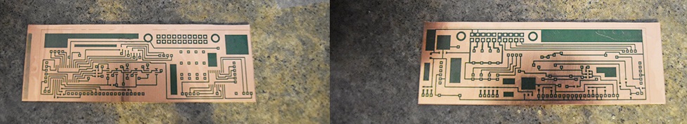
The board is placed in a bath of ferric chloride which dissolves away the exposed copper to leave just the tracks behind.
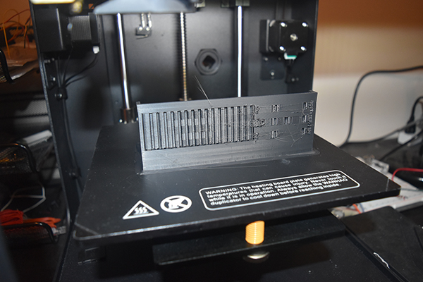
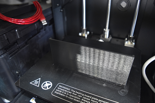
The next step was to create the housing which I 3D printed from ABS, this was not ideal and I wish I had later used PETG. The front of the panel was quite delicate, it required a lot of sanding and paint.
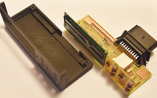
The board was drilled and all of the components were soldered to it. Finally the board was placed into it's housing and held in place with resin, this also protects the board from moisture and debris.
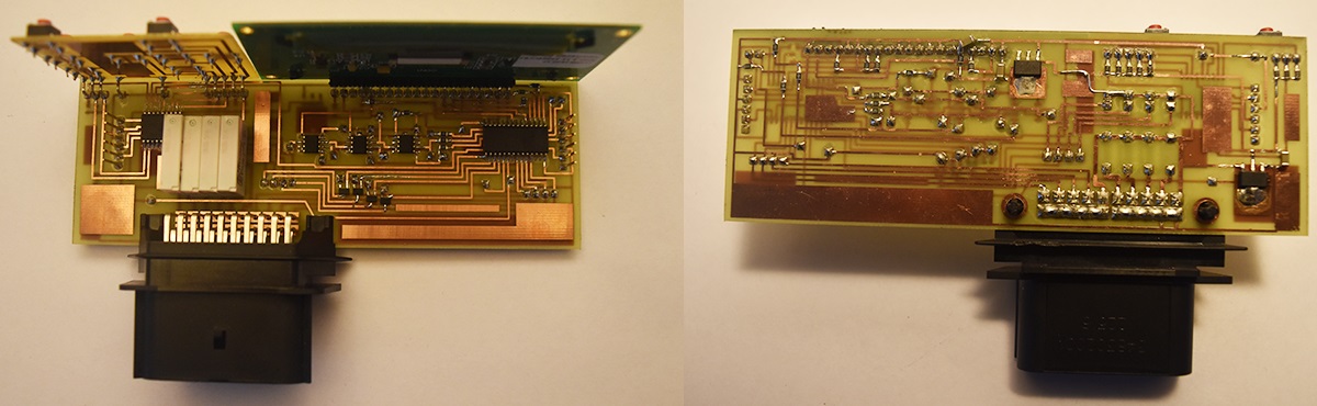
Here are both of the components before being fixed together with resin, I did of course test the board before doing so.
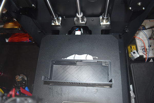
The tray that will hold the module was printed from PETG. The reason I held this project off for so long was because I originally tried to print this part from ABS and had some serious issues with warping. I later ordered some PETG and the result came out perfect.

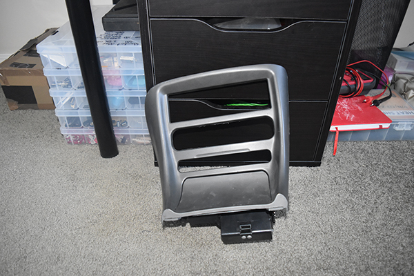
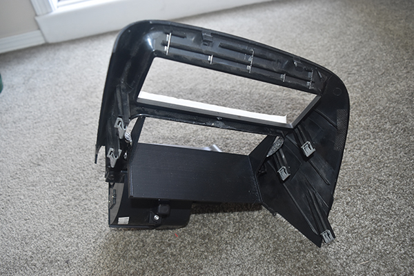
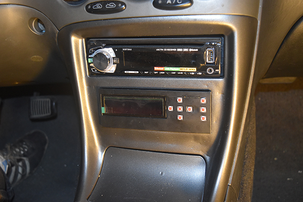
This is the center console of my dashboard, the top slot for the radio, the bottom two were for a storage hole and a cup holder, obviously not needed. I cut a hole to make room for the tray.
The tray was super glued in place and then taped over.
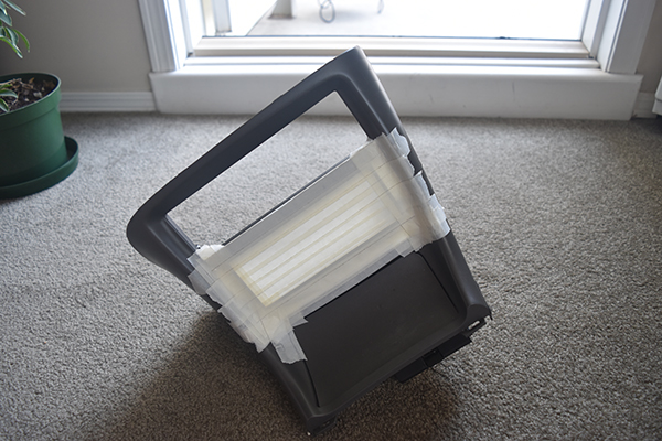
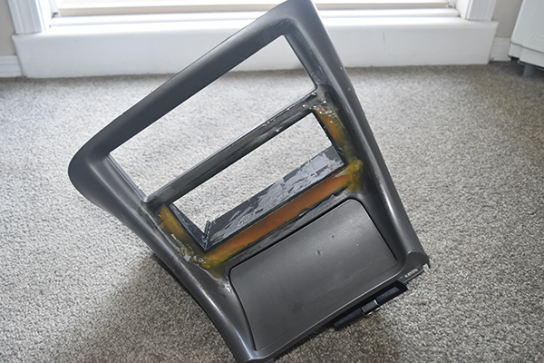
I used fibreglass and some resin to permanently hold the tray in place.
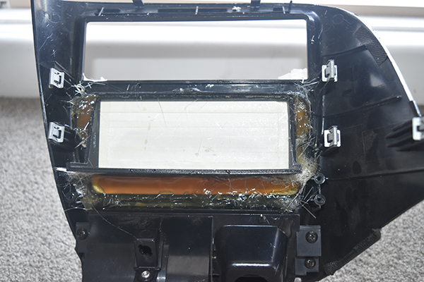
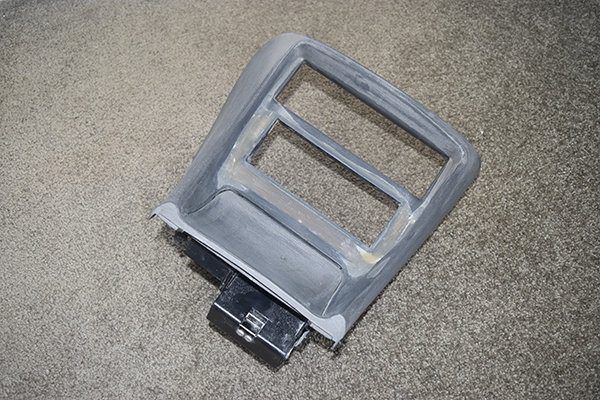
I mixed up some more resin and filled in the gaps, I really should have used car filler which I later regretted. I did some sanding to blend it all together, it didn't come out perfect but I believed at the time it would look ok.
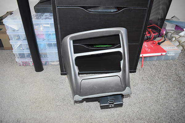
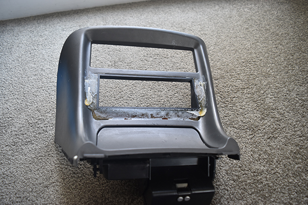
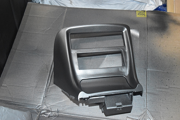
I gave it a lick of paint to find that there were a lot more imperfections than I first thought. It is ok for now but I'll probably remove it another day and blend the imperfections with some car filler. The module fit perfectly, it will be a flush fit when I sort out the wiring, I left it protruding so it could easily be removed.
The next part of this project is to wire in the power supply and program the module, this will be on the next page. As of now the car is running the standard ECU so this interface can only be used to control auxillary functions such as power to my AFR display, I wanted to be able to turn off anything illuminating as not to attract unwanted attention.
Hello, if you have enjoyed reading this project, have taken an interest in another or want me to progress one further then please consider donating or even sponsoring a small amount every month, for more information on why you may like to help me out then follow the sponsor link to the left. Otherwise you can donate any amount with the link below, thank you!