Exploding Water?
An exploding wire is an idea that's been around for quite a while, it's the basic concept of a high current being pushed through a thin piece of wire, the fast rise of current causes it to explode. When the wire is vaporised current still flows in the form of a plasma, it is this high temperature plasma that causes the air to expand so violently that it causes a bang, it can also burn the air. Due to the process vaporising the wire it can create nano particles, so small that the oxygen in the air would cause them to ignite. The shockwave produced is so strong that it can detonate plastic explosive, in fact due to the minute times involved it is the method used in the trigger system for a fission bomb. Plutonium is wrapped in a high explosive blanket, detonators are placed evenly around the outside, the explosive compresses plutonium against a core pip of beryllium and Polonium, the shockwave initiates a neutron source from the pip, the neutrons initiate fission when they hit the plutonium. If one detonator was to be even a micro second out then it would detonate the explosive unevenly destroying the bomb.
Anyway I'm not making anything of the sort, I'm going to try to observe the effects of an exploding wire in air and then water. The exploding wire in air is not much use but in water it should be a different story, especially with it being almost incompressible. There are quite a variety of applications, one of these is the forming of metal sheets into moulds as a very high pressure is produced. The other could be in weapons, for example a peak of 60,000psi is the maximum pressure found in regular cordite munitions, peaks of 1,500,000psi in wire-water detonation. It however does not mean that it will produce a more powerful weapon, these are just peak's and they could be too short to even do anything.
Unfortunately I live in the UK which means that I cannot build a weapon, the law defines "a lethal barrelled weapon of any description from which any shot, bullet or other missile can be discharged", I assume lethal being 12ft/lb or 16 Joules. I could scale it down to a minute level, but I could not guarantee me not exceeding this. So I guess I'm left with just measuring the pressure and trying to determine the physical power produced and then predicting what a weapons power would be. I do hope to hydroform some metal or just make some crazy high powered press.
November 16/11/2015
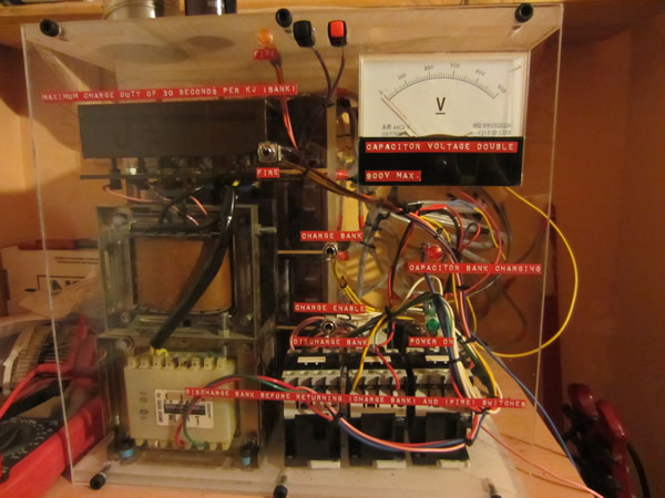
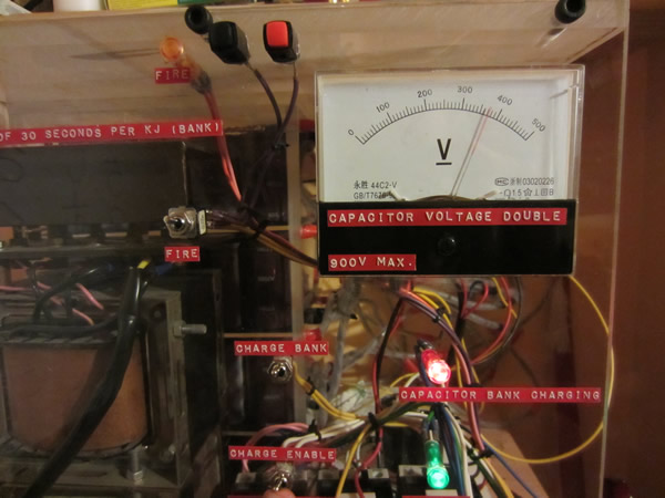
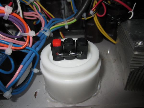
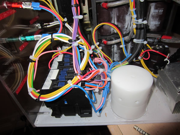
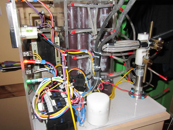
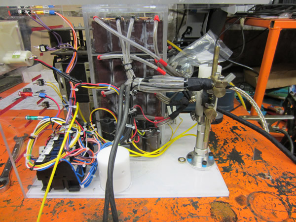
A while back I built myself a 8kJ capacitor bank for the fusion project, after realising that the currents generated would not be high enough I put it aside. It now seems that I have found a purpose for the bank, so the first thing was to make it into some kind of a self contained unit. I made a panel with various switches on it to allow me to charge, discharge and fire the bank at a safe distance. I then linked a couple of contactors together with the charging circuit, making sure that the mains power is isolated from the 900Vdc.
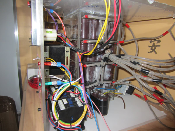
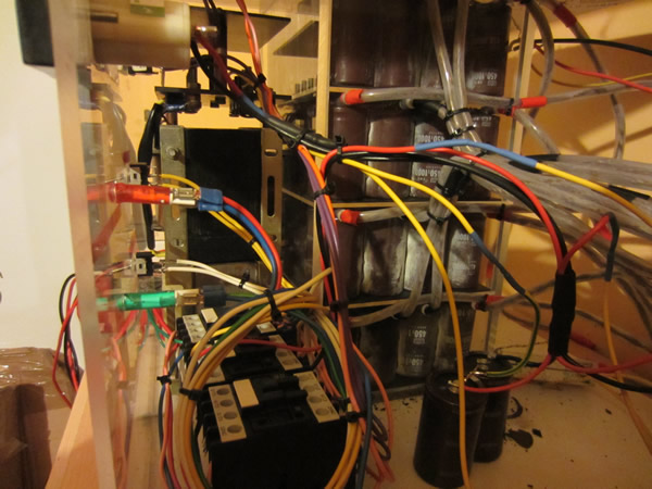
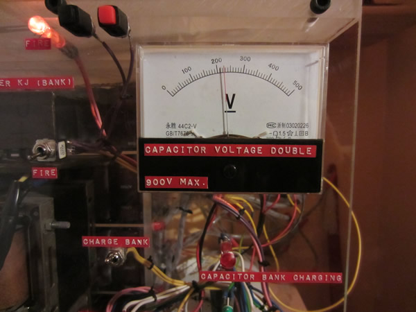
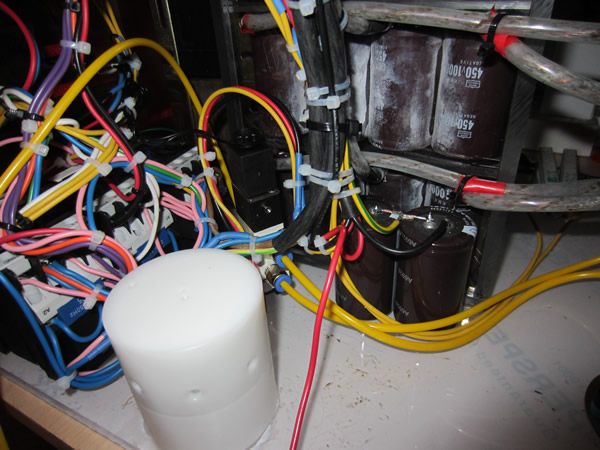
Below are two pictures of the bank so far.
A couple of days later I sorted out the rest of the charging circuit with the addition of the voltage doubling capacitors and the resistor discharge circuit. I performed a couple of checks with the continuity meter to make sure there were no shorts and then connected the unit to a variac, then to the mains. I did a couple of tests charging and discharging the charging circuit, up to a maximum of 900V. I took it to just 920V and blew a charging capacitor, it did however give me a little warning hiss. I have had these capacitors up to 1000V before, so it could be that they are faulty, or the supply voltage might be peaking above the maximum rating, although unlikely due to the size of the capacitor.
The green lamp is to show that power is supplied to the unit. The red lamp is illuminated when the "charge enable" and "charge bank" switches are thrown, this is when the capacitors are being charged, hence the voltage meter climbing. When the "fire" switch is thrown is disconnects the charging circuit and actuates a contactor, the contactor can be used to supply the high current switching circuit. A capacitor bank this size will have a huge amount of leakage, when the charging circuit is disconnected the bank will quickly start to discharge. Instead the bank continues charging until the "fire" switch is thrown, this minimises lost power and also gives me greater accuracy in calculating power stored.
All that I now need to do is to create a switching system to dump all of the power through whatever the load is. It shouldn't really take a great deal of machining, I need ensure that the contacts can be changed, 8kJ is a hefty amount of power.
November 22/11/2015
Today I designed the heavy duty switch, it will utilise a pneumatic cylinder to make it all automated, basically I don't want to be around when I switch it. I bought a heavier duty resistor to discharge the bank, 800W discharge at full charge, it will still be a minute before it is safe to touch. I will be just playing around with the bank when I get it fully functioning, probably seeing what gauges of wire it will explode, if it will explode them. I will only know if the wire has exploded properly if the majority of the bank has discharged, this will prove that a plasma has been produced, ish. The only real way is to see if a super-sonic wave has been produced or isolate the nano particles in an inert gas and see if they then burn in the atmosphere. The current should be around 9kA due to the ESR of the capacitors or 8.1MW of peak power.
My other plan apart from destroying some fruit is to try and measure the pressure created by this thing. I'm going to need to create some kind of vessel, big enough to contain some wire, but not that big that I can't fit it in the lathe or lift it. I'm thinking of some steel around a diameter of 100mm, bore of about 40mm going down to a bore of 10mm, this should translate down to a reduction of 16, this can then power another 40mm cylinder down to 10mm, a total reduction of 256x, then to a pressure transducer. My pressure transducer is rated for 200bar, or 2900psi. This all means that I should be able to read up to 51.2kbar or 743kpsi. I will be using water as my fluid medium which does compress meaning that the actual peak pressure will be dampened and unknown, the steel will also expand. Using Barlow's formula I get that the burst pressure will be 36,000psi and using a different formula I get 60,000psi. What does all of this mean? Well its a hell of a lot less than I thought, but the tensile strength of mild steel is 60,000psi. Also if I was to use something like vanadium steel for the piston with a tensile strength of 120,000psi it would be no where near strong enough at these pressures.
November 23/11/2015
I have done a lot of thinking today and searched for some answers on a forum for thicker walled tubing, a couple of people confirmed my findings. It seems that I was going about this the wrong way, these pressures are high enough to make diamond. For some reason I thought that making something thicker would make it stronger but I failed to realise that the pressure rating will only increase to the tensile strength, wall thickness effectiveness decreases exponentially, so there is very little difference between a 10mm wall and a 30mm wall. It seems as though I will have to take a different approach, the effects it will have on hydroforming and then to determine pressure through burst disc analysis.
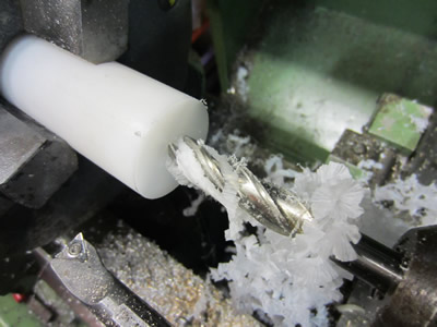
On a plus note, I have received some parts today, the solenoid valve and the push-fit hose parts. I though I would finish off some of the charging circuit by making an enclosure for the charging diodes. There will be quite a large amount of back emf in the circuit, greater those with an inductive load such as a coil. The diodes will probably get destroyed in the process, I have seen this occur and it's quite dangerous to be around. It can also happen if they are no replaced after a high back emf load, they may not explode, but will when charging the bank, this is especially dangerous. I found out some plastic parts that I had made from another project, I was going to throw them away too. All I had to do was stick them back in the lathe to make some of the steps longer or recesses deeper, the ventilation holes were already there.
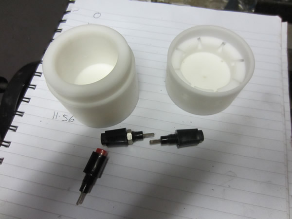
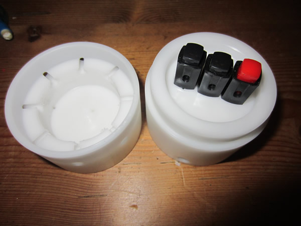
The whole lot was then assembled, placed in the setup and then glued in place. The cap can be removed to replace the diodes, I do have 500 of them so should be good for at least 250 discharges.
November 25/11/2015
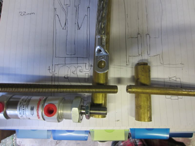
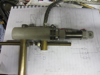
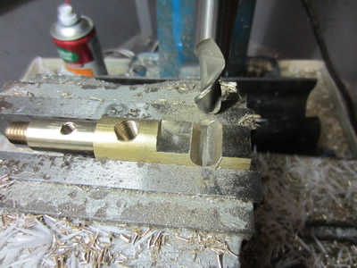
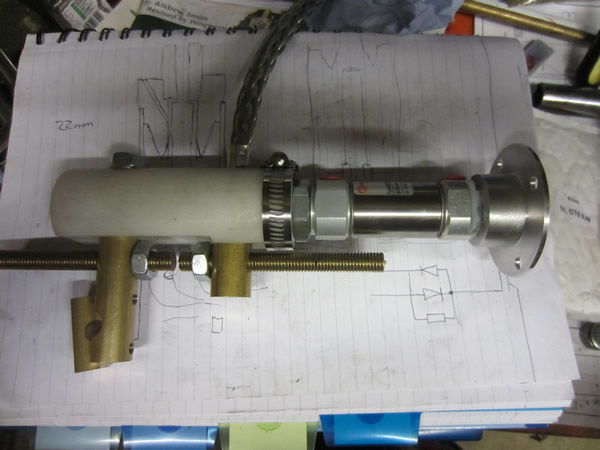
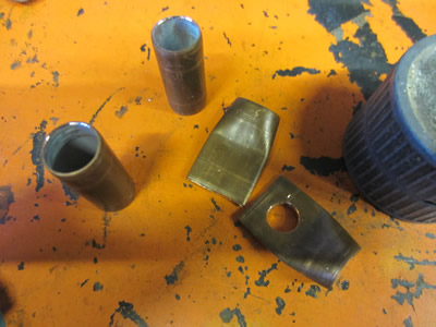
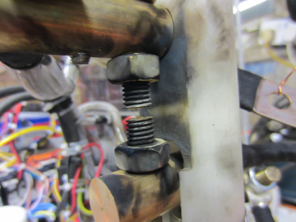
I got the actuator through the post today so it was time to make the heavy duty switch. I laid it on paper to get an idea of how it would go together, the design is actually different to the outcome (ignore the writing on the paper, it's a diagram for something else). I started with the piece of brass that will connect the actuator to the output lead, the picture shows two different taps as the pitches are different from the actuator to the threaded rod. I chose to use the miller to start the tapping process, it ensures I have two parallel threads.
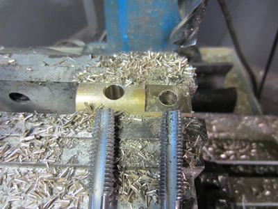

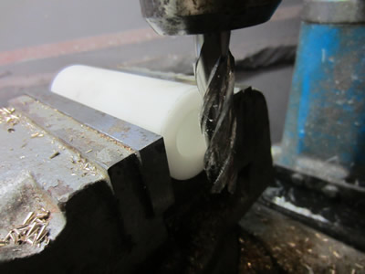
Both sides of the switch must be isolated from one another so I chose to make the body out of acetal. I first drilled, bored and then tapped the bore of the rod, the actuator will screw into this thread. The next step was to slot the body.

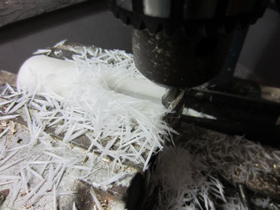
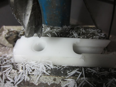
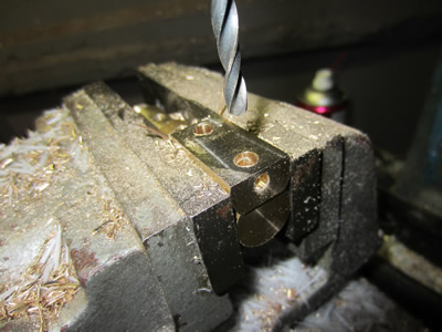
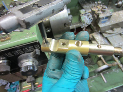
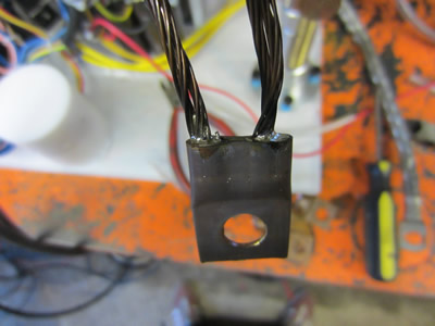
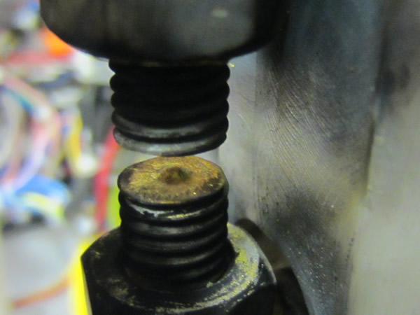
The slot was milled to allow the actuating parts to slide down into it. A hole further down was drilled and recessed to allow the bar for the other contact to fix to. The last picture shows it all assembled, I manged to make the second contact without taking a single photo. Due to the slot down the centre of the body it left few threads for the actuator to screw into, so I chose to use a hose band to squash it onto the threads.
The second contact will be connected to the bank, so next on the list was something for the 12mm power lead to clamp into. I chose to use a ball nose cutter to give the cable more surface area to conduct.
I chose to make a foot out of some aluminium bar, it's some really easy stuff to machine, so easy that I forgot to take pictures of me making it. It's basically a flange with four holes, the centre was tapped so that the actuator would screw into it. The switch was complete so I fixed it to the unit with four bolts, I tapped the perspex as I didn't wan't live bolts protruding out of the bottom.

The next step was to plumb in the pneumatic system, it was simply connecting the actuator to a solenoid valve. The solenoid valve air input was connected to a pressure gauge and then to a stirrup pump, the design is that it will be connected to a portable gas cylinder instead. The coil was wired up to a miniature power supply and then to one of the contactors.
I turned it on, flicked all the neccessary switches and turned up the voltage on the variac to 850V, at 880V the charging capacitors started to hiss. I flicked the "fire" switch and the system worked perfect actuating the cylinder and completing a circuit. I chose to try it with the charging capacitors only as the discharge resistors are not safe to be running at higher powers, I also need to make a shroud for the contacts as the flash will be too bright.
November 26/11/2015
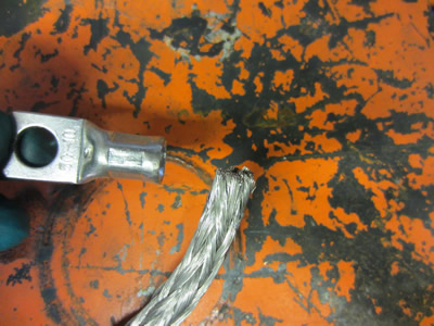
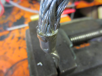
The large cables are crimped together, I was not too sure how strong these crimps would be so I pulled one apart, quite easily I must add. I made the decision to solder them all in place, it has reduced some of the flexibility but I'd rather that than them coming apart.

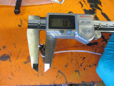
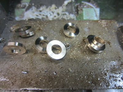
The capacitor bank is split up into eight separate banks, I want to be able to change the amount of power that I'm dealing with by adding or removing a bank. I chose to cut it down to four banks, each bank had a ring terminal crimped and soldered on.
Some spacers out of brass were made to link all of the terminals together. These spacers ensure that as much contact surface is used as possible to reduced resistance and increase current capability.
The whole bank is complete apart from the discharge resistor which I'm still waiting for. I made a couple of tests to see if the switch was up to the powers I'm going to run at. The final test was at 5.5kJ, a little nerving as the discharging system was nowhere near adequate. I chose to record the last test, it's just a short, I wore ear plugs as I knew the bang would be rather loud, so loud that the shockwave pushed the camera. The diodes were destroyed after each shot due to the high back emf produced by the inductance of the system.
The contacts seem to be holding really well, I do have a 400fps capability on my compact camera so it might be worth trying.
November 28/11/2015
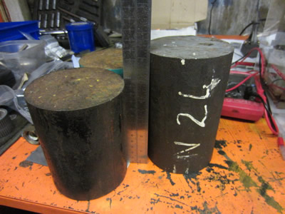
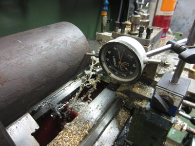
Yesterday I bought some 100mm round pieces of steel, two at 125mm long and one at 160mm long. The two are EN8 which has a yield strength of 67,000psi and an ultimate of between 72,000 and 116,000psi. The longer piece is EN24 which has an ultimate strength of 120,000psi. My choice material was the EN24 if I could machine it but I feared that it would over hang in the lathe too much, the chuck over hangs by quite a large amount already. I don't have any steadies nor do I have a centre, so I placed it in the lathe with the clock at the end, I pushed against the steel and it moved about 0.03mm. I feared this was on the limit for my lathe but I thought I would give it a try.
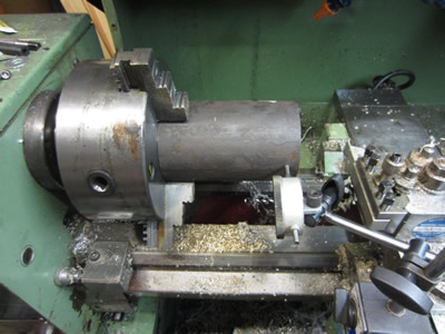
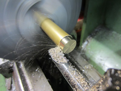
The face of the material machined like a dream, perfect blue spirals of swarf and a mirror finish. The outside was a different story. The outside must have been case hardened as it was near impossible to cut, just vibrating or tearing the material no matter what speed I run it at. I tried different tools, different inserts but I finally gave up, it was too hard and the lathe was not rigid enough.
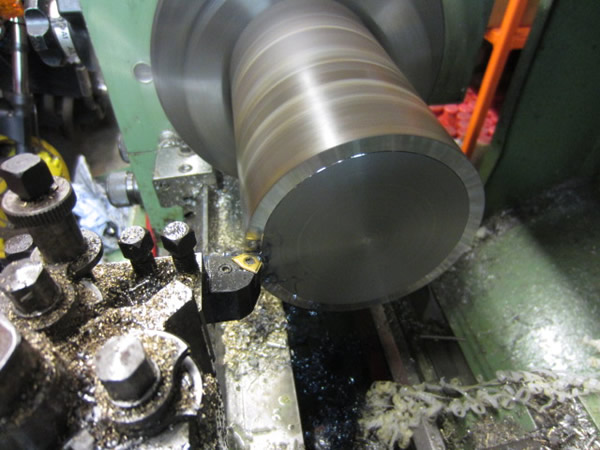

Instead I stuck a piece of the EN8 in the lathe, the face machined exactly the same which left me a little nervous. The outside was turned with a feed of 0.1, the cutting was intermittent and I was left with a mirror finish. It seems as though this material is going to be easier to work with, even with high feeds like this it was quite easy to turn.
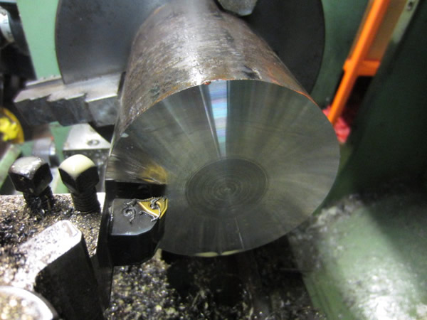

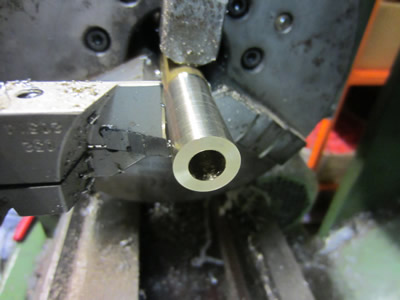
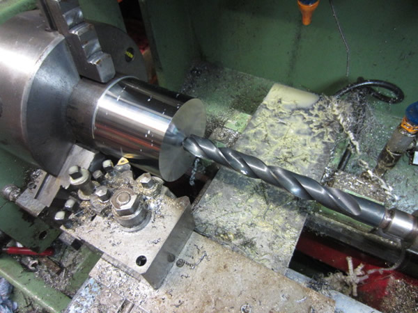
I turned the outside to a diameter of 98mm, it was just to clean the outside to a nice number. I started to drill the centre out with a 22mm drill bit but it proved to be problematic as coolant wasn't getting to the tip. I instead went for a half inch drill as it was TiN coated, the drill bit was only just long enough.
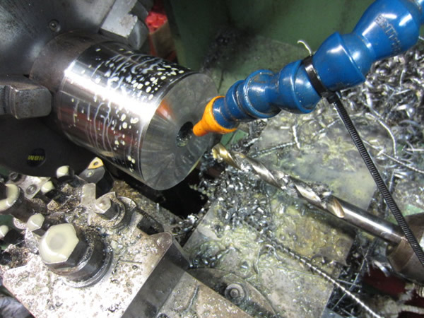
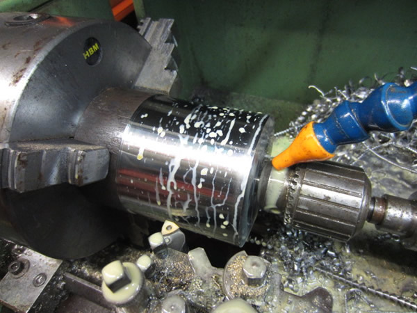
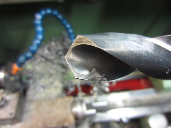
I put the 22mm drill back in the lathe to open up the hole, the first picture is before I bored it out with the smaller drill. I managed to get about half way in and the drill bit chipped, I will have to wait until tomorrow to grind it up as it's too late at night.
Hello, if you have enjoyed reading this project, have taken an interest in another or want me to progress one further then please consider donating or even sponsoring a small amount every month, for more information on why you may like to help me out then follow the sponsor link to the left. Otherwise you can donate any amount with the link below, thank you!