Inertial Confinement Fusion
I first attempted to make a fusion setup to achieve it through a "z-pinch" concept but I was unlikely to succeed by this method. I instead opted to go for the inertial confinement route as I had a TIG welder and the money to do so.
April 23/04/2014 - Age 21
I'm definitely going ahead in making a Farnsworth-Hirsch fusor and will be starting construction very shortly, below is a plan of my setup;
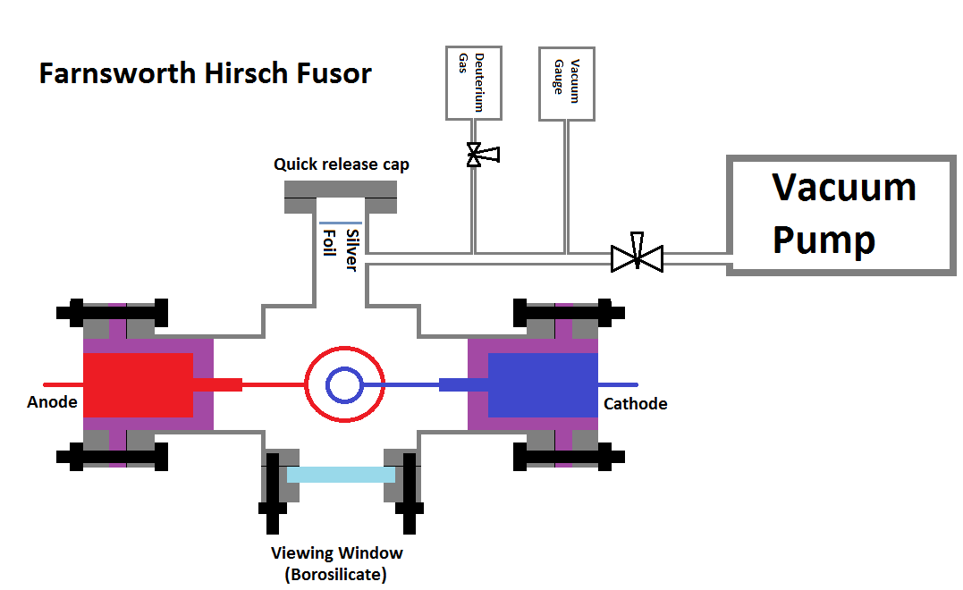
In basics its a stainless steel vessel with four port flanges. One of those ports is just a viewing window shielded by borosilicate glass. Two of the ports hold in place the metal grids, these are going to be held in place by PTFE - an insulator. Sealing will be aided by o-rings and the steel rods going through the PTFE will be sealed in by resin, its much easier. One of the ports will have a quick release, beneath this is a piece of silver foil (explained later). The whole system is connected to a vacuum pump through a needle valve, when the vacuum is at its lowest the valve can be closed and the pump turned off. A digital vacuum meter will measure the pressure, a needle valve between a tank of Deuterium can release the gas when desired. The whole setup seems pretty simple, but I'm sure that I may have issues with the sealing.
One of the most important things to consider about this project is the proof of that neutrons have actually been emitted. One of the first ideas that I had was to collect samples of the gas and have it analysed, but this would just be awkward. Anything using electrical methods such as a scintilator may just be too inaccurate due to the magnetic interferences. A bubble detector was mentioned, but these can be expensive, plus they only have a limited shelf life. One method that I never really gave serious consideration was the use of silver foil. When the neutrons hit silver foil it causes a change from Ag-107 / Ag-109 to Ag-108 and Ag-110. These two forms of silver are now radioactive emitting Beta radiation, the half life of both of these isotopes are very short, where Ag-110 is only 24.6s and Ag-108 is 142.2s. The reason for the quick release on my fusor is so that I can measure this radiation while it is pretty high.
I have been looking into my power supply which has proven to be quite difficult. The only real two power supplies that are suitable are those from an X-ray unit or from a neon sign transformer. The problem with the X-ray transformers is that they are usually three phase, extremely large and heavy, plus they don't come up for sale very often. The neon sign transformers don't seem to exist in the uk second hand, well not at the voltage that I'm wanting, so unfortunately I would have to buy one brand new. I have found one rated at 10kV at 100mA, if I use a voltage doubler and crank up my variac then I can achieve 33kVdc. Just a quick note to anyone reading this, adding a capacitor to this output makes this power supply very dangerous, without doubt this would kill me If I was to touch it. I will also be buying some panel meters, one for the current and one for the voltage. The voltage in the fusion chamber will only increase as the vacuum increases, unless very high currents were used, which would result in the grids being destroyed. I have started enquiring and buying parts, I will give an update at the weekend.
I have bought two high voltage diodes rated at 25kV at 2A, unfortunately they are not quite high enough for what I wanted, but limiting the supply to 25kV should be ok. I have put diodes in series before, but if the diodes are not equal then there may be a higher voltage across one diode than the other leading to its ratings been exceed, bypass resistors can get by this but I'm not messing about like that, otherwise I would spend more money and buy a higher rating diode. The supply will incorporate a voltage doubler, which will also require two capacitors. Now the voltage rating is easy, about 25kV upwards, but the capacitance is not so simple. The transformer is rated at an output of 500W which therefore means that the capacitors need to hold a decent amount of energy so they don't drop to zero, I want them to drop 1kV at the most. Follow the calculations below, basic electrical knowledge would help before reading;
Power = Voltage x Current
500W = 25000V x Current
Current = 0.02A
t = CV/I
where t = time, C= capacitance, V = voltage drop when discharging capacitor, I = current
tI/V = C
t = 1/50Hz
t = 0.02s
(0.02 x 0.02) / 1000 = 0.0000004F or 0.4uF
This therefore means that I need a capacitor of the above value for the voltage to drop only 1kV through one cycle.
To check my calculation I can use the following formulae for capacitor discharge;
Vc = Vo e^(-t/RC)
assuming that the resistance is 0.02A/25000V
R = 1,250,000 ohm
Plugging all of this into the calculator, I get a value of 24kV which means all of the calculations should be somewhat correct.
Even though the supply will only be drawing 10J per cycle, it means I need a capacitor rated at 125J for it to only drop 1kv. A larger capacitor would allow the voltage drop to be less, although this would be more expensive and dangerous. Now this is taking into account that the two capacitors have been combined, chopping them in half means that I need two capacitors rated at 12.5kV at 0.8uF. Which is proving difficult.
April 27/04/2014 - Age 21
I have been doing a lot of searching and buying. So far I have bought some stainless tubing and sheet to fabricate the fusor vessel, it is all out of 316 stainless, I have bought some 316L TIG welding rods. I have bought a neon sign transformer rated at 10Kv at 100mA, it is unused but has slight cosmetic damage for a discounted price. A geiger counter for testing the silver activation. 160 of 20kV 10nF ceramic capacitors for the voltage doubler. A 40kV voltage probe and a 100mA ammeter. I still have quite a few things to purchase such as the setup for electrolysis of the deuterium oxide into pure dry deuterium gas. A cabinet for the high voltage supply. A glass window for the fusor, borosilicate or quartz with a UV coating will be used. And there's the whole of the fabrication. I've probably spent about £600 in the past week, the budget is probably around the £1000 mark as I already have quite a few of the other parts required.
April 03/05/2014 - Age 21
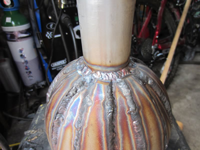
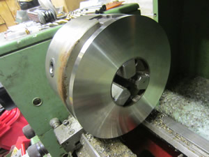
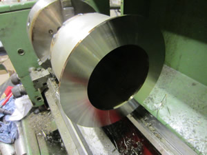
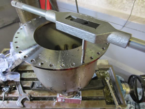
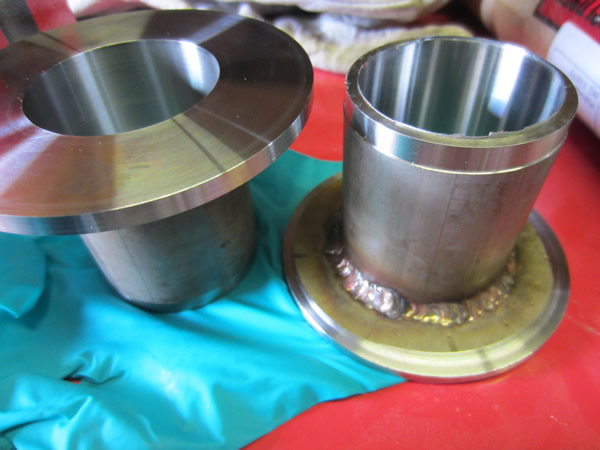
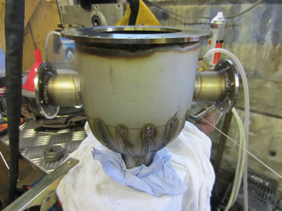
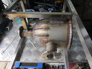
I started construction on the fusor vessel today as I have received most of my items. Today went ok with the construction, although not quite as well as I had hoped. The tube diameter is 168mm.
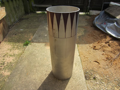
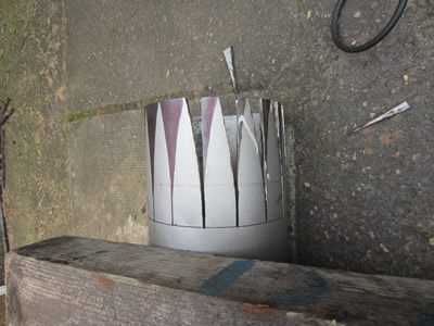
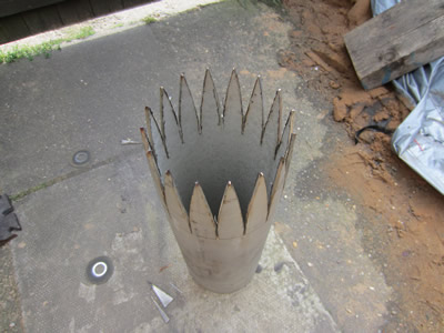
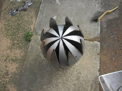
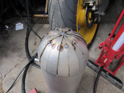
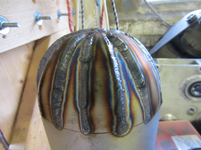
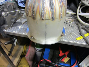
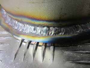
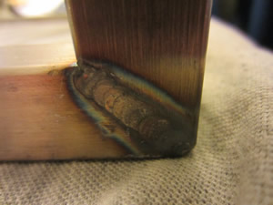
I spent quite a bit of time working out the exact size that the leaves need to be, so that when bent inwards it would form a perfect hemisphere. I spent quite a bit of time grinding them out, but unfortunately I didn't quite take enough off them, probably another 0.5mm all round would have sorted it. It was getting too late in the day to start grinding again, so making them over-lap wasn't too much of an issue. I chose to make a dome on the end of the tube as I had bought a large piece, I would rather make use of it than to buy some more metal sheeting to make a flat end. It had been a long time since I had TIG welded any stainless, it didn't go too great to begin with but the welding improved.
Apart from all of this I have received all of my items except for the capacitors. I bought some tantalum wire to be used as the grids, these have a very high melting point - similar to tungsten.
April 04/05/2014 - Age 21
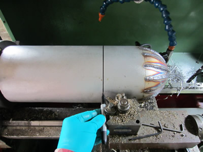
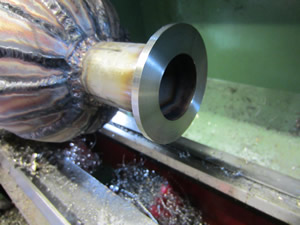
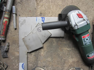
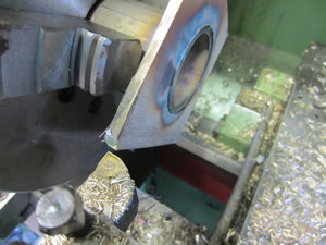
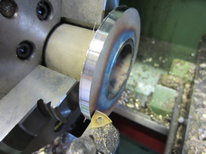
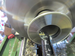
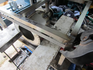
I did a little bit more on the fabrication of the fusor. I first marked out where I was going to cut the tube, then turning the frequency down on the lathe's inverter I could spin the tube at 10rpm. Using a part-off blade would be a bad idea, so I used the angle grinder - reason for the blue roll on the lathe's bed. Unfortunately the grinder burnt out so I had to cut the remainder with a hacksaw. I put the cut tube into the lathe, faced and bored a hole inside of it, it took a while because the cutting was intermittent. I then machined a piece of tube to fit inside of this hole and then welded it into place, my welding ability seems to be improving. I then held the smaller tube in the lathe and faced off the larger diameter end, amazingly it turned out concentric after welding.
As for the rest of today I started work on making the flanges out of a piece of stainless sheet, I cut two squares out and welded them together. I will then use a hole saw to cut out the inside, the two smaller discs will also be used to make flanges. My milling machine doesn't go slow enough, so I will have to wait until I go to work to drill this hole.
The whole of the fusor will be housed in a casing, so that If I want to view it closer, I can without the risk of electrocution. It means that I must get the fusor complete within the next week so that I can start ordering perspex, I must also order some more stainless box-section to make a frame, the frame will of course be insulated from the main chassis of the whole unit. I have also started designing some of the valves for the vacuum pump and for the deuterium gas cylinder. I received confirmation of my capacitors being dispatched, they are from china, so may take a while.
April 10/05/2014 - Age 21
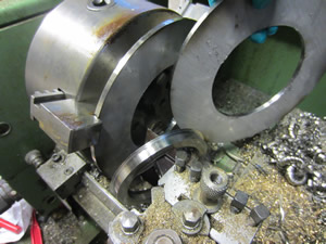
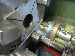
I've tried to get on with the construction of the fusor and it began with making the large pipe flanges out of a piece of 5mm sheet. I first cut out two equal squares and then welded them together, using a line from corner to corner I found the middle point and cut out the center using a hole saw. The hole saw is intended to cut stainless, but it took a real long time, about 2 hours in total. I welded the inside of the hole and put the whole thing back into the lathe after first cutting off the corners with the angle grinder. I turned the outside and the face to a rather superb finish, stainless can be very nice to machine.
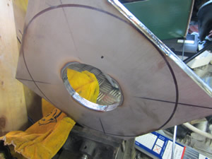
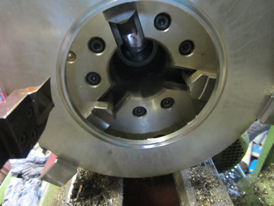
I used a special face grooving tool to cut out rings from the center of the plate which therefore separated the welds, this tool was certainly a lot faster than using a boring bar. I welded the flange to the fusor housing, my welds certainly seem to be getting better. I put it back into the lathe and faced it off, the finish came out to a mirror.
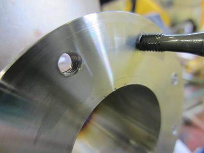
I stayed behind after work today to drill the holes in the large flange, but due to the milling machines inaccuracy I needed a different solution. Instead I created a smaller flange from the left-over discs from the hole saw and welded it to the small diameter tube on the fusor, then cleaned it up on the lathe. I clamped this side on the millers bed and clocked the flange to find its center. I drilled out the 36 holes and then tapped them to M6, unfortunately I broke a tap, but due to the holes being so closely spaced together it doesn't really matter if a bolt is missing. I didn't manage to finish tapping all of the holes because this material is really good at blunting the taps and I need to buy some more.
I was hoping to achieve fusion by the end of this month, but I'm really unsure if I will be able to get it all done by then. I'm sure I will be able to run it on argon, but there is a lot of work in making the deuterium gas.
June 06/06/2014 - Age 21
I'm currently on holiday in Canada visiting family and doing a little career prospecting. Unfortunately progress on the fusor will be limited as I'm here for a couple of weeks, although I did do a little bit more before I left. Previously on the fusor vessel I had a total of 36 holes to put an M6 tap through, but the steel was really good at destroying these taps. So shortly after I purchased a cobalt tap which did double the amount of holes without blunting, I also bought a 6.5mm TiN coated drill bit to do the other flange. I had also broken one of the taps in a hole but I managed to TIG weld an old allen key to it and extract the tap.
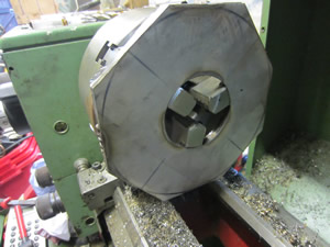
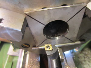
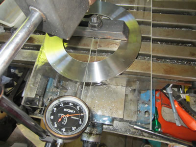 The next part to be machined was the flange plate that will be bolted to the fusor vessel. I first cut out the inside diameter, I love this tool, it beats the boring bar.
The facing proved to be quite difficult as the plate was still slightly bent, so cutting was intermittent, and all it did was chatter. I turned it at a speed of 50rpm, a feed of 0.025mm and faced about 0.5mm which after a 15 minute pass came out to a mirror.
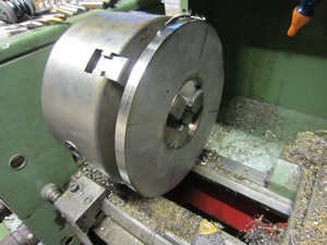
I then put it into the miller and clocked it central, I wish my milling machine was a little bit bigger as the Y travel is only about 110mm.
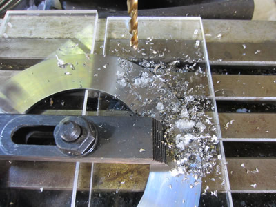
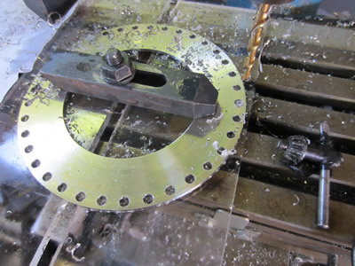
Milling took quite a bit of time as I first had to drill a 5mm pilot hole before then finishing it with the 6.5mm hole.
Only 20 of the holes could be drilled in one operation, rotating the plate 180 degree and getting it aligned was a bit of a guess.
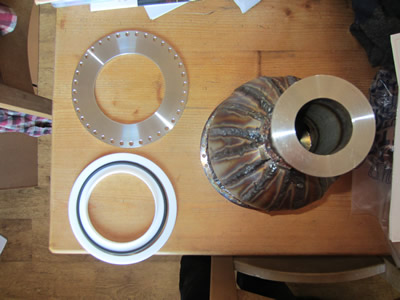
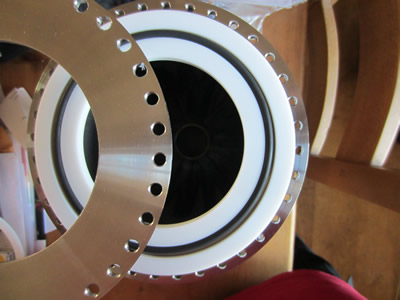
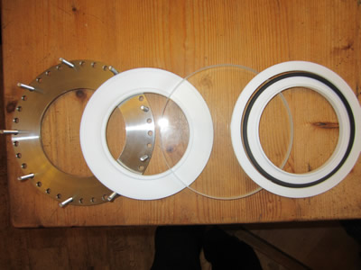
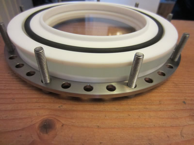
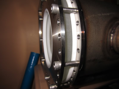
I wanted to get the other half of the flange done so that the face wouldn't get scratched as it will be sealing a high vacuum. I made a gasket from PTFE and used a Viton O-ring for sealing, both high temperature materials. The O-ring is required to have a back-up ring both sides of its sealing, the outer to stop it distorting and the inner to stop it from extruding to the inside of the vessel. There will be a borosilicate glass viewing window that will be sandwiched between the flange and these seals. The flange holes did not perfectly line up, this was expected due to the first inaccuracy of the milling machine I used at work, but due to me drilling 6.5mm holes it all came out ok.
I have been looking into the different types of material that I could use for the fusor window. I would have previously liked to use something like a borosilicate glass, although this could prove to be expensive. Plastic such as acrylics have high out-gassing properties which are not always the best, but they are great barriers against neutron radiation. The cost of a borosilicate window will be approximately £100 whereas the acrylic one will be £10, I think the acrylic may be the first option.
June 22/06/2014 - Age 21
I'm back off holiday and have had to wait until the weekend before I could use the angle grinder. I've done little work because of other commitments, but some progress is better than none.
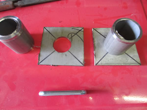
I first cut out two stainless sheets and connected each corner with a marker to find the centre.
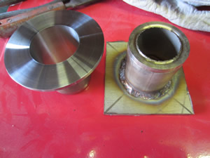
Using various operations I drilled and bored the centre to allow two sleeves to push into the holes, these were prepared earlier.
The sleeves were then welded to the plates followed by more machining operations such as turning the outside, face and boring the bore to a tolerance of ±0.01mm.
Overall I'm quite happy with the results so far, the finishes are good and the welds are improving. Tomorrow at work I will drill out some holes in the flanges.
Drilling out the holes in the fusor vessel for the above flanges will be the most difficult part. I bought a hole saw that is intended for stainless, it works great in the lathe but not so much in the milling machine. My machine is not up to the task so it means using the one at work, which isn't very accurate, luckily it doesn't have to be. I will have to wait until next weekend because there is probably about 2 hours of machining time and it all must be done in one operation to ensure everything aligns.
June 29/06/2014 - Age 21
I managed to drill the holes in one of the flanges, but unfortunately it killed my drill bits. I managed two holes with a TiN coated drill bit before it melted, these were high quality and have been great in the past. I then used a carbide end mill which really isn't designed to drill holes, I managed to finish, but I wasn't even going to risk the other flange.
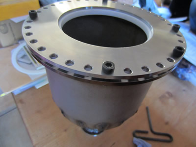
Apart from this I drilled out two holes in the fusor vessel to house these flanges, this was my most feared part of the whole fabrication.
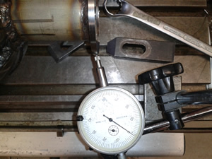
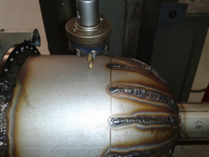

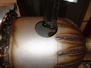
I first placed the whole thing in a dividing head placed horizontally, I rotated it with a clock against the end of the flange to make sure that the whole thing was running square. Using careful measurements I used certain reference points to ensure the hole would be where I wanted it, I also used the same reference points again when I indexed the dividing head 180 degree so that the holes would align. Using my hole saw and a lot of water I drilled a hole through the side at a diameter of 38mm, surprisingly easy. I then used a boring head to increase the hole to a diameter of 48mm, tolerance of ±0.01mm. I did the same to the other side of the fusor vessel, amazingly it all ran pretty smooth, I'm glad because a lot of work has gone into this so far.
Due to my work and open university commitments I have found very little time in this past week, as will be the case the following week, but I intend to get the setup complete in under a months time. I did a little bit of thinking about the Deuterium gas, which I had intended to produce from Deuterium Oxide. Electrolysis is the process in which I would make the gas, it is not difficult but rather time consuming, I only have 50ml of deuterium oxide which would result in a very small electrolyser. I used to make hydrogen gas when I was about 14/15 and I know that it could take me hours to collect enough gas at such a small scale, the gas would also be wet which is a major concern as it needs to be dry. I have contacted my original supplier to see if they could supply me with a 10L lecture bottle, if they can I will probably sell on the deuterium oxide as it has the most interest on my site. I have also bought a 99.9% pure silver coin to aid with the neutron detection, amazingly its cheaper to buy a rare coin than to buy wire or foil, unfortunately I have to drill a hole through the middle of it.
July 04/07/2014 - Age 21
I did a little more work in my lunch time at work, it involved drilling the holes in the remaining pipe flange, I bought a carbide drill bit. After work I welded these flanges into the fusor vessel. Due to the flanges being such a tight fit and there being no gap I welded it without the aid of a filler rod, the welds came out exceptional. I then tapped the holes in the flanges. The next step will probably to make a frame for the vessel and complete the electrodes.

July 19/07/2014 - Age 21
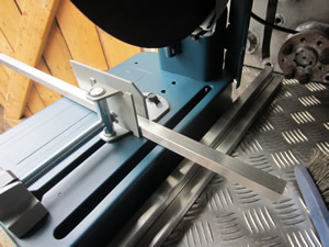
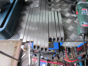
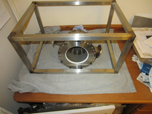
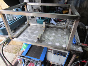
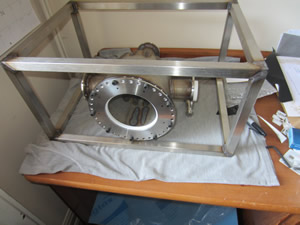
Today I bought myself a cut-off saw to cut up some stainless I bought for the fusor frame. I eventually cut it all up, did some further grinding and then welded the whole thing together. Tomorrow I will weld the fusor vessel inside of this frame, I will also make the electrodes.
Between last week and up to now I've been enquiring about different items for the fusor. The main one being the glass viewing window which has to be made from borosilicate glass to withstand the thermal shock, the other main reason is that its very good at blocking neutron radiation when compared to regular soda glass. Quartz (ideally) or borosilicate glass tubes for the electrodes, they require an insulator. Deuterium gas - I had originally bought some deuterium oxide in which I had intended to split through electrolysis and collect the gas, unfortunately this would be a slow process. I got some replies and basically got all of these items sorted out, they just require purchase. I'm first seeing if I can get the deuterium gas off a cheaper supplier first and I'm currently waiting for them to review my order.
On the plus side it means that I can sell on my deuterium oxide which seems to be very difficult for people to source, my website gets a lot of interest through the deuterium, and due to it being pretty much harmless it means that I can sell it on an internet auction site.
July 20/07/2014 - Age 21
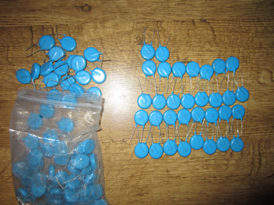
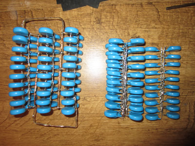
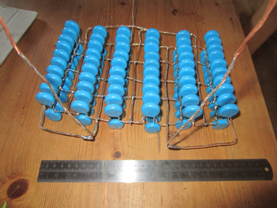
I had previously bought some capacitors from China to make the voltage doubler for the power supply, I thought that it was about time that they were all soldered together. I straightened out all of the legs and soldered them in some kind of order, I did not use all of the capacitors that I intended to use, 120 instead of 160 mainly due to the size of them. I will be purchasing some casting resin as the leads are close and I definitely don't want any arcing.
The next step was to finish off some of the welding in the frame that I made yesterday, there were still quite a few gaps I had not welded. I then made some blocks for the fusor vessel to sit on and then welded it all in place. Welding was rather stressful as the mask could not decide whether to turn on or off - an automatic exposure mask.
I did not have time to make the electrodes as I had to get on with some of my studying. I also need to design some valves for the vessel so that when I create a vacuum it can then be disconnected from the fusor. The reason for disconnecting the pump is because the pipe connecting it must be metal as a rubber hose would be far too porous, the metal is conductive and the fusor vessel will be live. Running the fusor on something like argon gas should be achievable in the next couple of weeks, hopefully before august.
July 26/07/2014 - Age 21
 My first purchase of the deuterium gas got rejected so instead I purchased it from my previous supplier along with some borosilicate glass for the viewing window and some for the electrode insulators. I also forgot to order the resin for the capacitor bank.
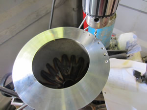
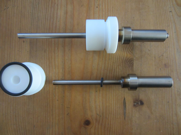
Apart from this I started work on the electrodes which are also made from stainless steel. The ends of the steel rods contain a thread in which the wire grids will be screwed in to. I used PTFE as the insulator and two viton O-rings to seal the whole thing. The next step for the electrodes is to make some cooling fins, a flange to bolt it to the vessel and the wire grids.
I had a play around with my vacuum pump and some of the fittings, I ended up with a needle valve that seems to be ok for the application. I previously tried to make these valves myself, but they were awkward and the stainless got used for the electrodes instead. The fittings seem to hold a vacuum for long enough but my pump doesn't seem to be pulling a high enough vacuum, I will try changing the oil.
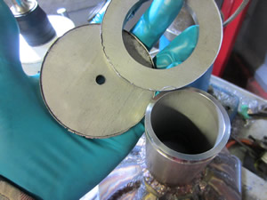
I had also made a cap for the silver activation port, but I'm not happy with the finish so it will be remade, I have also made some seals for this port. The lead time for my order is around three weeks so in this time the fusor should be almost ready to run, I will not be running it on deuterium gas straight away as I will need to perfect the setup, more likely helium gas. When it is run on gas I will be making a video to prove my results, and make some calculations. Then thereafter If I have created fusion I will then buy some scintillation material which will emit a light when hit by a neutron, work will may then commence on the z-pinch.
August 25/08/2014 - Age 21
I've had a lot of studying to do, and just life in general has had my mind astray, so I've just not had the time to do anything. Although all of this doesn't matter as I have not received my glass window yet. Once I receive this and finish off some of the general work then it should be ready for fusion. One big problem is that my supplier let me down with the deuterium gas, on the plus side I did not sell my deuterium oxide. There is one more supplier to try for the deuterium gas, unfortunately its 40L of gas and its about £250, I should be able allow for this. I have ordered some of the valve work, its mostly nickel plated brass, stainless was far too expensive. I was going to solder it all together, but I may as well just buy some vacuum sealant, then I can reuse the valves if I need to.
August 27/08/2014 - Age 21
I finally bought some resin to cast the capacitor bank inside, the delivery only took a day, so tomorrow I will make a casing to pour the resin into, it will also act as a little more insulation. I ordered some more of the valve work that is required to finish off the remaining pipe work, this should be ready to pick up in a couple of days, some of it is in stainless so that I can weld to it. I bought some vacuum grease to seal the whole system when the valves have been screwed together, the grease should not creep and remain sealed for its lifetime. The best part is that I finally received my glass, so I made a couple of spacers and screwed it to the fusor.
Within the next week I will have completed most parts of the fusor including its power supply, this means that it should hopefully be able to run on something like Argon gas. I will make an electrolysis setup for the deuterium oxide and perform fusion on the date its created and when everything is perfected.
Hello, if you have enjoyed reading this project, have taken an interest in another or want me to progress one further then please consider donating or even sponsoring a small amount every month, for more information on why you may like to help me out then follow the sponsor link to the left. Otherwise you can donate any amount with the link below, thank you!