Inertial Confinement Fusion Page 2
August 28/08/2014 - Age 21
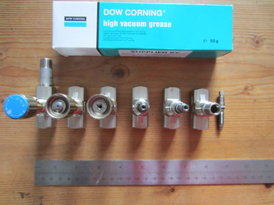
I picked up the remaining pipe work parts, I will probably weld the parts together when its the weekend and then assemble the whole thing when I get the vacuum grease through the post. Apart from this, I thought I should give it a go at casting the capacitor bank in resin. I had some old acrylic sheet which I cut up and taped a box together, I placed the capacitors inside and then poured a clear casting resin. I wasn't quite expecting the kind of heat that it was giving off, literally it was steaming. After a couple of hours the resin had set and cooled down, unfortunately it had large cracks running all the way through it. The cracks don't really matter as it was mainly to keep the capacitors in position, due to the resin being clear it should allow me to see if any arcing occurs, hopefully it shouldn't.
August 29/08/2014 - Age 21
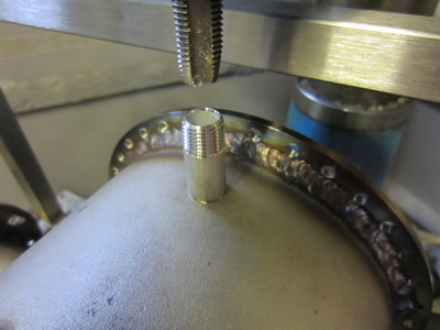
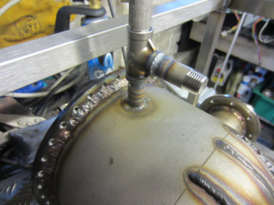
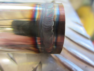
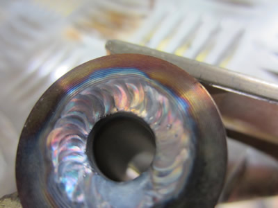
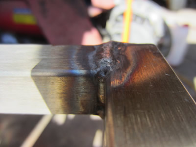
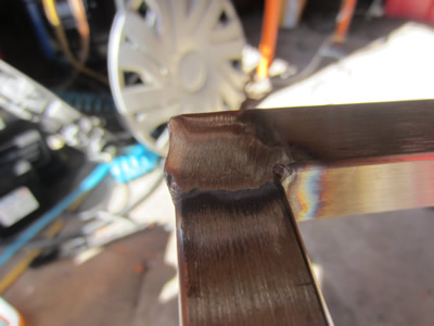
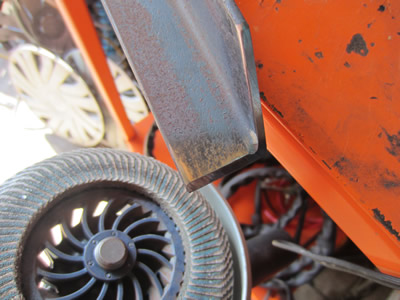
I thought I would do a little bit of fabrication. I put the whole fusor into the milling machine, drilled a hole and tapped it to a 1/4 BSP. I then screwed some of the fittings in and then TIG welded all of the gaps. The rest of the valve work will be finished tomorrow, I also got my vacuum grease through the post which will be used to seal everything.
August 30/08/2014 - Age 21
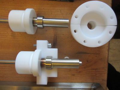
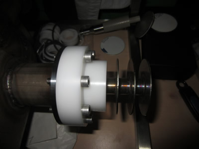
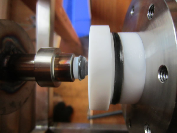
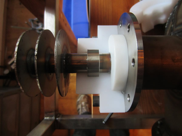
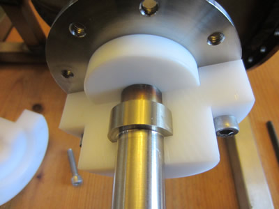 I made some flanges for the electrodes out of polyacetal, a general engineering plastic. They had to be split into two parts by the aid of a bandsaw.
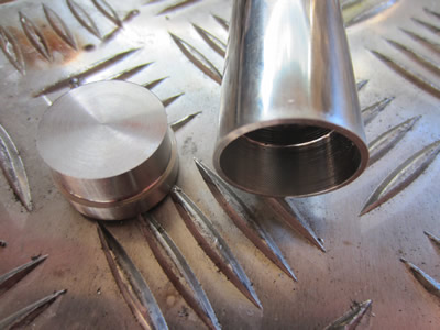
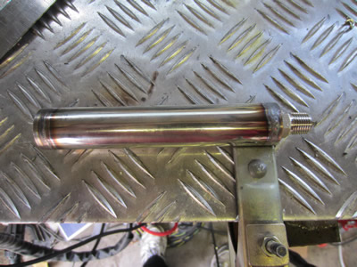
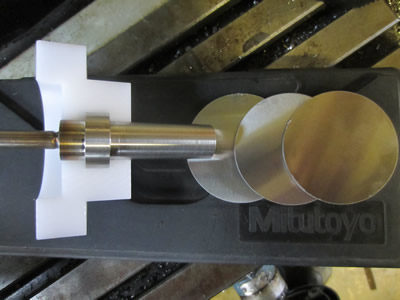
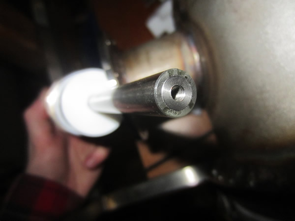
The stainless electrode part now just requires some cooling fins, I have bought some metal discs, I'm just awaiting them through the post.
I was going to make the wire grids that bolt on the end of the electrode today but I can do this on my dinner break at work.
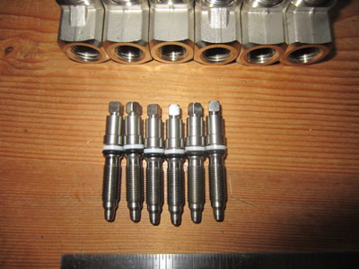
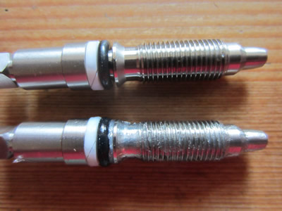
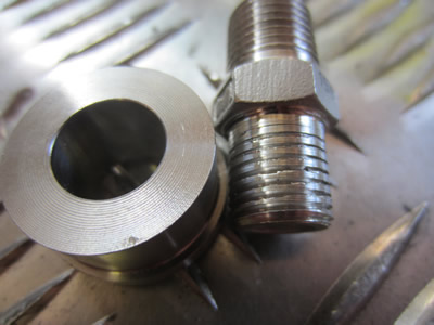
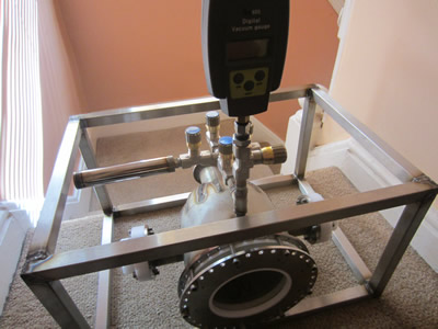
The next step was to get some of the valve work done, I started by dismantling the needle valves and coating the internals in high vacuum grease. I did assemble all of the valve work but did not take any pictures, there is the odd finishing touch to make before I do so.
August 31/08/2014 - Age 21
The deuterium gas canister is next on the list, all 316 stainless as usual. Nothing is the fusor vessel has to bear any pressure, even the storage tank for the deuterium gas. There will be a surplus amount of deuterium even if the tank is filled at atmospheric pressure, which it will be. The whole of the system will be evacuated down to a pressure of around 20 microns, while this is happening I will be creating deuterium gas through electrolysis. A valve will then be opened drawing the gas through a desiccant and then into the storage tank, when I'm ready to perform fusion another valve will be opened releasing the gas into the fusor vessel.
September 01/09/2014 - Age 21
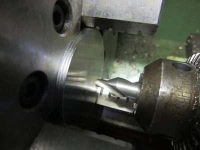
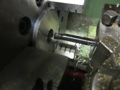
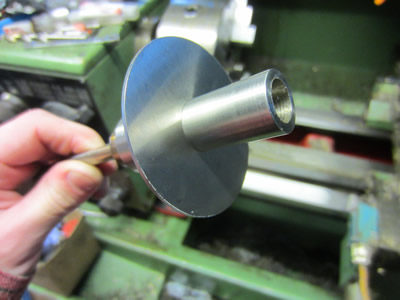
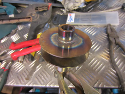
I received the stainless discs through the post (total of eight), these will be used to try and dissipate a little bit of the heat away from the electrodes, although stainless is not a great conductor of heat. Stacking three together, drilling and boring them in the lathe was a lot easier than I expected. They were placed over the end of the electrode and welded in place, I have to say that my welding mask is becoming a real problem, it can't decided whether to be on or off, which makes welding impossible. The discs also warped really bad when welding, I straightened them at best with a pair of pliers, one electrode done, one more to go, tomorrow.
November 16/11/2014 - Age 21
I had forgotten how close I actually was to achieving fusion, so today I made a start on it again. I machined and welded the discs to the remaining electrode, inserted some O-rings and vacuum grease to the assembly.
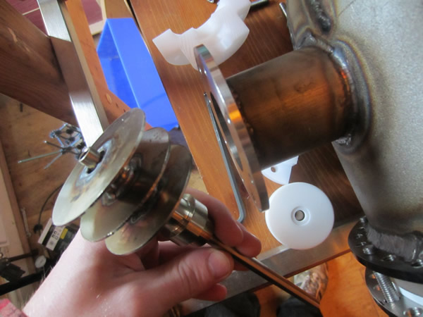
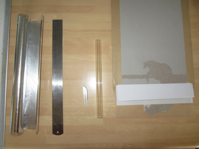
I had bought a 1m long piece of precision borosilicate tube, it was a lot cheaper to buy a long length than have it cut. To cut the tube I scored around the diameter a few times with a carbide insert, wearing some gloves I bent the glass and broke it at this seam, it split perfectly. All this was a bit of a shot in the dark because I had no idea how I was actually going to cut it, I expected the glass to fragment. This electrode is now ready for the sphere. I bought some tantalum wire a while back and had a go at welding it using the laser pulse welder at work, it did not work as there was no gas to shield the weld. I did a little bit of research into welding the wire, it turns out that TIG and spot welding is the preferred method, I will give TIG a go first. The larger sphere will be made from stainless as this will be bombarded by very few neutrons.
I have also bought some perspex sheet to cover the whole fusor, I do not want a shock from a 100J 25kV capacitor bank, it would certainly be death. Hopefully on my lunch at work I should be able to make myself a cap for the back of the fusor where the silver coin will be placed. Then after all of this, I will trial the fusor running on argon gas.
December 01/12/2014 - Age 21
It has taken up to now for the perspex sheet to arrive, I will have to wait for the weekend or glue it at work, the glue is a little potent.
April 06/04/2015 - Age 22
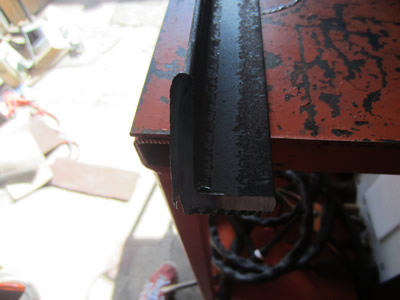
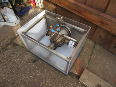
I have got a little tied up in another project, but now that one can be held back. Today I thought that it was about time that I glued together the perspex sheet that I bought a while back, the purpose is to insulate the whole fusor, I really don't want an electric shock. I ground down the welds on the fusor frame, it's a tight fit to stop the whole thing moving around.
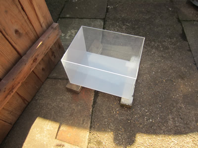
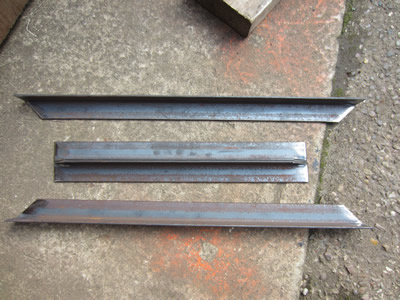
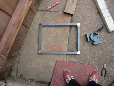
The next step is to fabricate a rack system to hold everything together, the first part is an under tray for the perspex box. It was made using angle iron with the parts mated at 45 degrees.
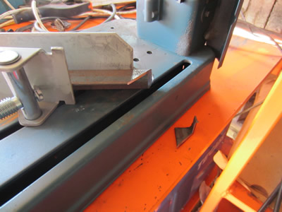
The whole lot was then welded together, ground ready for the rest of the rack. Before I continue with making the rest, I first must make sure that my power supply is suitable. My only concern is the capacitor bank, when the resin was cast an exothermic reaction took place, some parts cooled faster than others which resulted in large cracks to appear in the resin. I hope that arcing does not occur between these cracks, if it does, well I'll have to find a better capacitor.
April 12/04/2015 - Age 22
 Before I make the rest of the rack I need to test the power supply, if it isn't adequate then I still have time to change it. I set up the supply with it's voltage doubler, each of the diodes are rated at 25kV which means that I will not take the supply any further as I don't want to push them to their limits. With the setup I should be able to achieve 33kV DC, I'm assuming that the diodes will contain a stack that is balanced, but If I don't go past 25kV then there should be no possibility of it blowing.
I'm running the transformer through a variac so that I can limit the voltage supplied. I turned the voltage up to 22kV and then there was a little flash from the capacitor bank, the supply then shorted. It looks as though the diodes have blown in the process, I will have to make up a diode stack instead.
April 19/04/2015 - Age 22
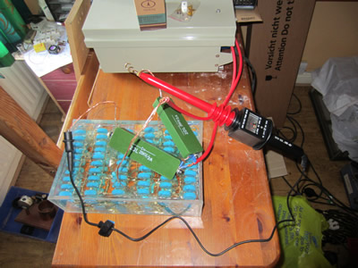
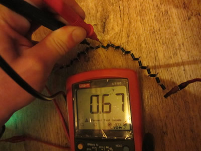
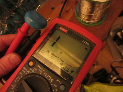
I was pretty certain that it was the diodes that I blown due to me only running the capacitors at half their ratings, however the bank was no good as an arc occurred through the cracks in the resin. I strung together 25 diodes in series, I thought that they should be balanced by resistors to stop leakage from blowing them, turns out that modern diodes should be fine on their own. I attached the diode string to the supply and the capacitor bank as a half-wave rectifier to see if it would go up to the 16kV limit, it was a short. I checked the diodes simply by passing a little current though them to see what the voltage drop across each one was, all were about 0.7V which is what they should be. I connected the string up to just two capacitors this time, I got to 16kV and there was a flash and the supply shorted. I tested the resistance of each capacitor compared to a new one. It seems as though one of the capacitors failed as the resistance was very low. I found my problem, these capacitors are faulty, seems I may have to go for a more expensive alternative.

I've had the idea of making my own capacitors from mylar film and kitchen foil. I should be able to get somewhere near the required capacitance for a relatively small amount of money, I think a couple of capacitors rather than just two will be best. The dielectric strength of mylar is 7kV/mil, I have bought two sheets at 5mil thickness to make a trial capacitor, this in theory should break down at 35kV, so 20kV should be quite safe. I have also bought a capacitance meter so I know exactly how many more mylar sheets I need to order.
April 24/04/2015 - Age 22
I received the mylar film through the post along with my capacitance meter. I first worked out the calculated capacitance from the calculator page, it uses the formulae; C = K x Eo x (A/D). Where;
Eo = 8.854 x 10 e-12
C = Capacitance (pico Farads)
A = Overlapping plate area (metres squared)
D = Plate Gap (metres)
K = Dielectric Constant
The plates for my capacitor are 260 x 170, the gap is 0.125 (mylar thickness) and the dielectric constant is 3.1.
I therefore get a result of 9710pF, the capacitor will be rolled up which depending on the number of layers will quite probably almost double the capacitance, I'm guessing in the range of 14 to 18nF.
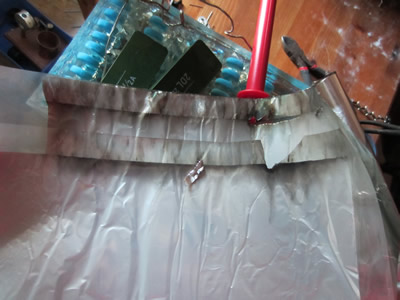
I measured out some foil to allow for an overlap of 260 x 170mm, one edge to overhang for the allowance of something to connect terminals to. I cut a piece of acrylic tube to wrap the hole thing around and then finished it off with a couple of tie wraps.

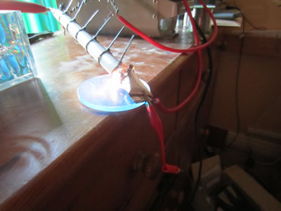
The capacitor looked quite neat, and when measured on the capacitance meter it was 15.56nF (managed to forget to take picture). I also measured the Chinese ones, which were 8649pF compared to their 10000pF label, not even within the 10% tolerance associated with ceramic capacitors. I connected my capacitor in series with diode chain and the transformer, I increased the voltage until I reached 15kV, there-after the dielectric broke down.
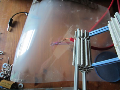
The dielectric didn't even withstand the 35kV that it should have done, I unwrapped the capacitor and it only occurred in one little area, but due to the power of the supply it ruined most of the mylar sheet leavening carbon deposits. I placed the transformers output wires between the mylar sheet, quite a large corona was present. I did do a bit of researching into homemade tesla coil capacitors, most people only allowed a maximum of 10kV per capacitor due to corona, instead strings of smaller capacitors were used. The other alternative was to submerse in oil, although I really don't like the idea.
For what this little capacitor cost me to make, it would not be cost effective to make my own bank, I need to find some manufactured ones and string them together. I will also go for polypropylene capacitors this time as they have high pulse capabilities, but more importantly they can self heal if the dielectric breaks down and some can be run at over three times their rated voltage.
April 25/04/2015 - Age 22
I have spent quite a bit of time searching for a cheaper capacitor bank and made myself an excel spreadsheet to work out the cost of each capacitor string and the cost per uF.
| Description | Cost | Voltage | Capacitance | Desired working Voltage | Quantity Caps needed | String Capacitance | Price per string | Price per uF |
| rs components | ||||||||
| 744-1458 | 1.76 | 1600 | 0.1 | 20000 | 13 | 0.008 | 22.00 | 2750.00 |
| 871-6728 | 2.4 | 1600 | 0.15 | 20000 | 13 | 0.012 | 30.00 | 2500.00 |
| 871-7030 | 3.09 | 1600 | 0.22 | 20000 | 13 | 0.0176 | 38.63 | 2194.60 |
| 871-6775 | 3.56 | 3000 | 0.15 | 20000 | 7 | 0.0225 | 23.73 | 1054.81 |
| 669-0016 | 4.06 | 1100 | 20 | 20000 | 18 | 1.1 | 73.82 | 67.11 |
| 669-0044 | 6.87 | 1300 | 25 | 20000 | 15 | 1.625 | 105.69 | 65.04 |
| 769-3062 | 7.2 | 1100 | 35 | 20000 | 18 | 1.925 | 130.91 | 68.00 |
| mouser components | ||||||||
| 80-F873DY154M760Z | 0.12 | 1500 | 0.15 | 20000 | 13 | 0.01125 | 1.60 | 142.22 |
| 871-B32914A5474M | 0.74 | 1000 | 0.47 | 20000 | 20 | 0.0235 | 14.80 | 629.79 |
| 871-B32914A5564M | 0.87 | 1000 | 0.56 | 20000 | 20 | 0.028 | 17.40 | 621.43 |
| 75-MKP1848510924K2 | 1.14 | 1200 | 1 | 20000 | 17 | 0.06 | 19.00 | 316.67 |
| 505-DCP4-2/1300/10L | 1.22 | 1100 | 2 | 20000 | 18 | 0.11 | 22.18 | 201.65 |
| 75-MKP1848520924K2 | 1.57 | 1200 | 2 | 20000 | 17 | 0.12 | 26.17 | 218.06 |
| 75-MKP1848C53012JK2 | 1.76 | 1200 | 3 | 20000 | 17 | 0.18 | 29.33 | 162.96 |
| 505-DCP4-5/1300/10 | 2.76 | 1100 | 5 | 20000 | 18 | 0.275 | 50.18 | 182.48 |
| 75-MKP1848S61010JY2B | 3 | 1000 | 10 | 20000 | 20 | 0.5 | 60 | 120 |
| 75-MKP1848S62010JY5F | 4.25 | 1000 | 20 | 20000 | 20 | 1 | 85 | 85 |
| farnell components | ||||||||
| 2420031 | 1.45 | 1200 | 3 | 20000 | 17 | 0.18 | 24.17 | 134.26 |
| 2420032 | 2.3 | 1200 | 5 | 20000 | 17 | 0.30 | 38.33 | 127.78 |
| 2420022 | 3.66 | 1000 | 10 | 20000 | 20 | 0.50 | 73.20 | 146.40 |
| 2133988 | 4.58 | 1000 | 20 | 20000 | 20 | 1.00 | 91.60 | 91.60 |
| 2420033 | 4.43 | 1200 | 10 | 20000 | 17 | 0.60 | 73.83 | 123.06 |
| 2420024 | 7.27 | 1000 | 30 | 20000 | 20 | 1.50 | 145.40 | 96.93 |
I found that from this table that the cheaper capacitors don't always make a cheaper bank. Ideally I want to make two banks of at least 1uF so that the supply is quite smooth, the supply is going to use a current limiting bank of resistors so that in the event of a short the pulse currents won't be too large to damage the capacitors. There is an obvious choice, the fifth item on the table, the cost per string and per uF are both very low.
I also need some bleed resistors across the capacitors to ensure that there isn't a lethal voltage after say one minute. If I choose the capacitors maximum rated voltage, 1100V, a time of 1 minute and a common resistor size of 750kΩ, plugging this all into the capacitor discharge calculator I get a remaining voltage of 20V, non lethal. The resistor will only draw a maximum of 1.5mA, therefore 1.65W of power per resistor, a total of 30W. If I double the value of the resistor then it will take two minutes to discharge the bank, it will also result in less power wasted from the supply.
Hello, if you have enjoyed reading this project, have taken an interest in another or want me to progress one further then please consider donating or even sponsoring a small amount every month, for more information on why you may like to help me out then follow the sponsor link to the left. Otherwise you can donate any amount with the link below, thank you!