Inertial Confinement Fusion Page 3
April 26/04/2015 - Age 22
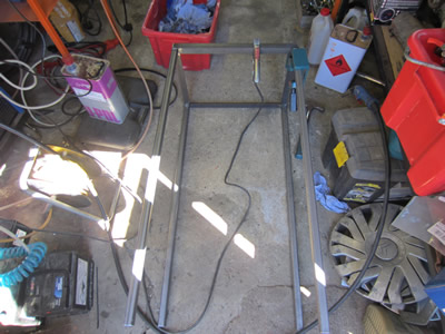
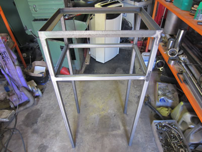
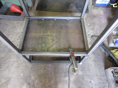
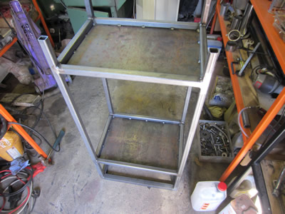
I went ahead with buying a total of 36, 1100V, 20uF capacitors and a total of 110, 470kΩ resistors. While I wait for these to arrive it must be time to get the rack finished. I first degreased all of the metal, a lot easier to do before everything is welded. I welded on the legs and cut out some pieces of tube for a shelf.
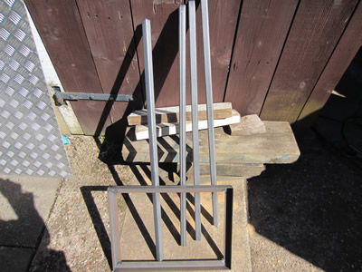
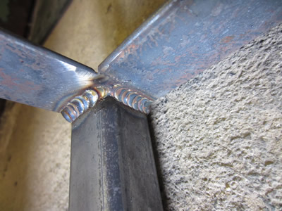
I welded all of the tubes in for the shelf to sit, I ground all of the welds on the outside to leave a better finish, the welds on the inside were left.
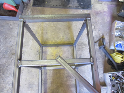
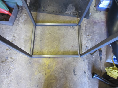
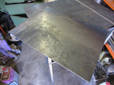
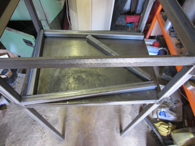
A shelf was cut from a spare sheet of steel, it was tack welded in place.
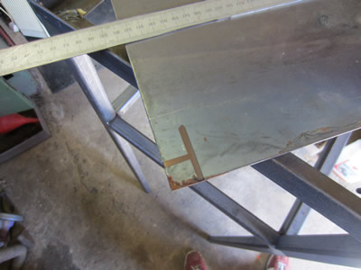
A couple of tubes were cut for a second shelf, welded in place along with another sheet of steel for the shelf itself.
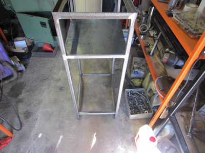
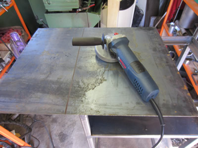
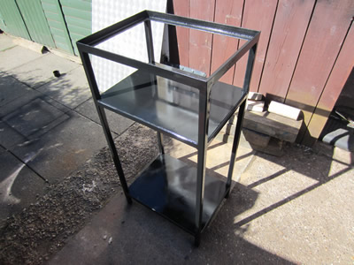
The whole thing was degreased again to prepare it for painting, it was then painted with just an average acrylic paint.
April 29/04/2015 - Age 22
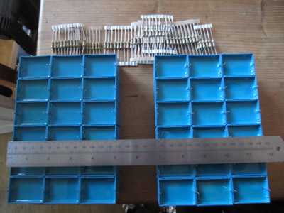
The capacitors and the resistors came through the post, so I got straight ahead with making the bank. The total cost of the bank and resistors came to about £145, not bad considering the ceramic bank was around the same price.
May 02/05/2015 - Age 22
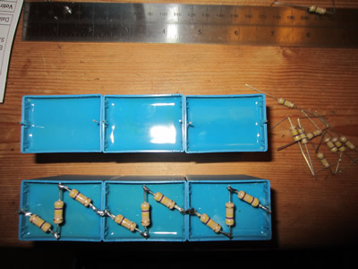
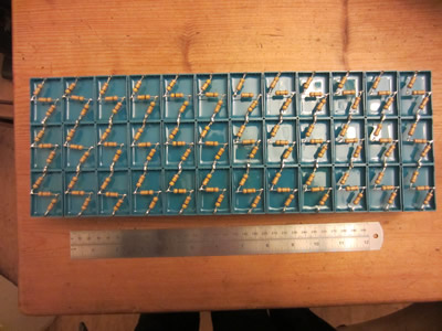
The capacitor bank was laid out to how it will be positioned, a small amount of epoxy will hold it in place and then it shall be placed in an enclosure, later on. I soldered in some link wires to make all of the capacitors in series, I also soldered two strings of 1kv, 2A diodes in series to make two stacks capable of 30kV each, 30 diodes a stack. The setup was then linked up to the high voltage transformer to test its operation, a chunky piece of perspex was placed between the "hot" end to ensure that no arcing would occur. The output of the transformer is 10kVac, which will be doubled, the variac's output is 270V.
So 10000Vrms x 2 = 20000Vrms (doubling the supply)
20000Vrms x 1.414 = 28284Vp (or 28284Vdc when rectified from ac to dc)
(28284 / 230) x 270 = 33203Vdc (running the transformer at 270V instead of its designed 230V)
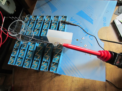
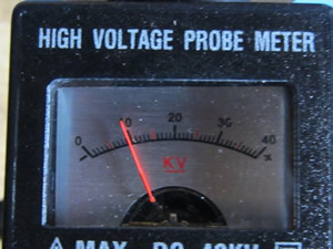
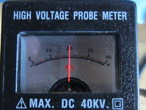
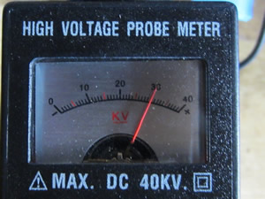
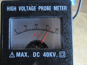
I switched on the supply and increased the variance slowly. At around 20kV I could hear a corona present, the supply still reached it's maximum of 33kV with no arcing and no component failures. I left the bank for a couple of minutes to make sure that it completely discharged itself.
May 03/05/2015 - Age 22
I have done a little bit of thinking about the power circuit, below is the circuit diagram.
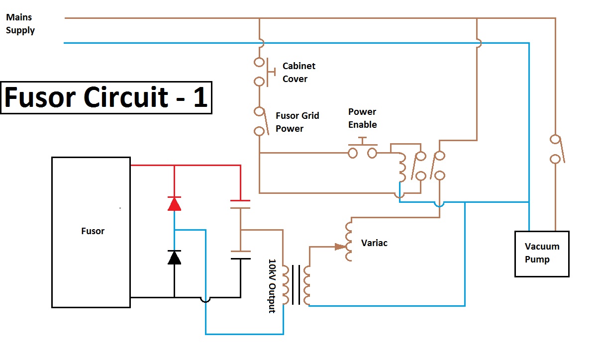
The power to the high voltage side is protected by a latching circuit and a system to cut power. There will be a switch on the cabinet cover so that when opened it will not allow any power to actuate the contactor, when the cabinet is closed it requires the user to press the enable button to latch the relay, this ensures that the supply cannot come straight on if the cabinet is closed and the power switch is left on.
May 11/05/2015 - Age 22
I have bought some perspex sheet to make a box for the capacitor bank, I have also bought a sheet to make the lid for the fusor. I think that some way of limiting the current going through my capacitor bank in the event of a short circuit may be a wise choice, a resistor bank, the lower the resistance, the lower wattage I will need. I'm assuming that the maximum voltage across the capacitors will be 33000V, and say that I want a maximum of 8A to flow in the event of a short circuit. 33000V / 8A = 4125Ω. I have chosen fifty 82R, 2.5W resistors to place in series, 4100Ω. I think the running current is about 100mA, so 0.1A x 0.1A x 4100Ω = 41W of power to be dissipated, the resistors are capable of 125W, so well within a safe working area.
May 15/05/2015 - Age 22
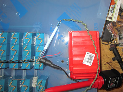 I'm still waiting for the perspex, but I have received the resistors. I soldered them all in series and then connected it up to the supply with a xenon discharge tube in series with it. When the tube reaches a certain voltage it will flash and short out the capacitor bank. I turned the voltage up to around 15kV where the lamp discharged at around 2Hz, there seemed to be no problems with the resistors. I turned up the voltage where the lamp became a constant arc, the resistor bank was fine with the 130mA short circuit current.
The bank equates to around 300J and with the current resistor bank would discharge in 100ms, that equates to 3kW of power. It's 24 times the working wattage of the resistor bank, I chose wire wound resistors so they could handle pulse power. When I get the supply enclosed in a box I can then test a short circuit at the maximum working voltage.
May 22/05/2015 - Age 22
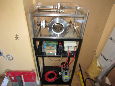
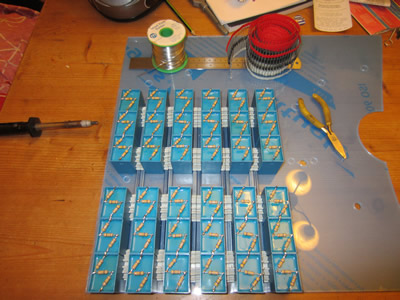
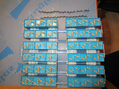
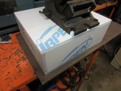
I finally got my perspex sheet through the post and glued it all together. I inserted the capacitors into the box and used a plastic constructional toy as spacers. The supply was tested at full power to make sure that the air would not ionise inside the box and cause arcing.

I have done a little but of thinking into the vacuum pump and how everything will operate. My problem is the transformer that I've used is centre tapped to earth, so it means that there is a potential difference between the output of the supply and the ground. Due to this I have insulated the whole fusor from its frame with the aid of a perspex box, now due to kind of voltage I'm using and the gas, it may cause the tube to the vacuum pump to act like a conductor. I don't power to be lost in an unintentional electron tube, so I will have to isolate the pump when I come to run the fusor. I first need to make sure that the fusor can hold a vacuum, or hold it long enough to perform fusion for a couple of minutes. If all is good then I will make some kind of automated system that disconnects the vacuum system.
June 07/06/2015 - Age 22
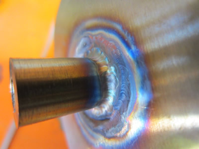
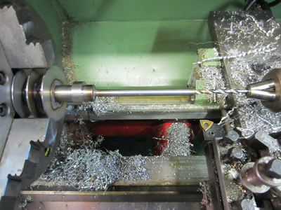
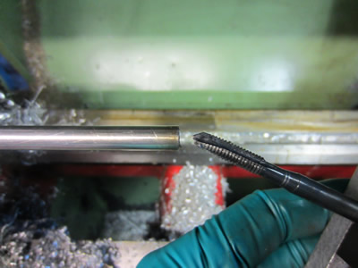
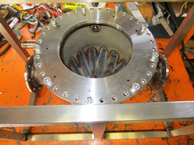
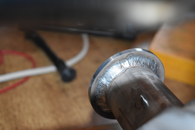
I had a mishap with one of the electrodes a while back meaning that there was no where to connect a power supply lead to. I made a little insert in the lathe to shove into the electrode, I then TIG welded it into place.
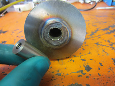
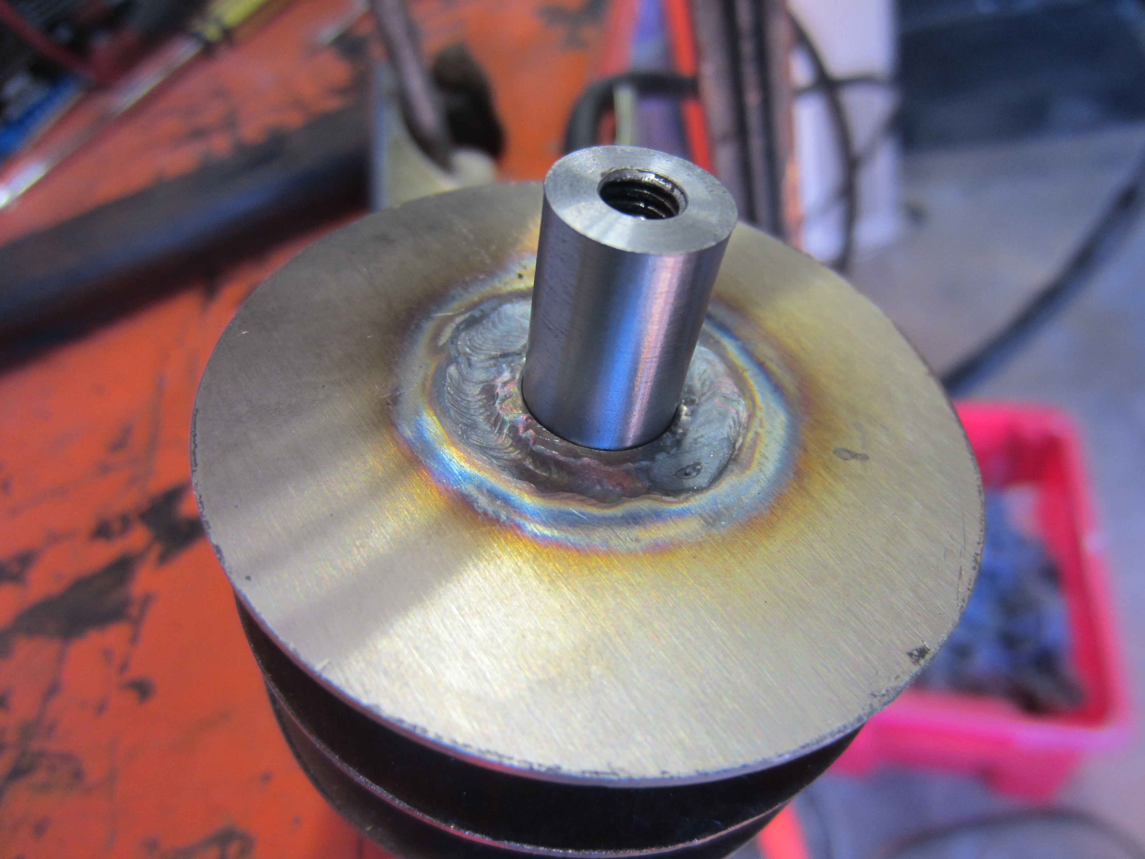
The electrode was placed in the lathe, it was originally drilled to suit an M4 tap but my taps were not suitable for stainless. I instead drilled it to 5mm and then tapped it to M6. I inserted the electrodes into the fusor housing with the aid of some high vacuum grease. A couple of weeks ago I received a piece of perspex sheet to make a cover for the top of the fusor cabinet.
June 08/06/2015 - Age 22
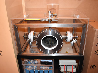
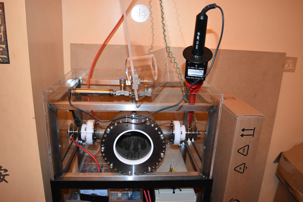 I decided that it was finally time to get the fusor ready to run. I started out by finishing off the power supply, the power leads from the transformer were soldered to the voltage doubler circuit. An ammeter was wired in series with the negative side of the supply, this was then connected to one of the electrodes. The positive supply still needs some way of insulating the power resistors, so for the time being I just propped them up with the perspex lid, just to test the supply.
I wanted to make sure that when the voltage is turned up all of the way that there would be no arcing to occur between the electrodes and the fusor housing. I turned the voltage up to 33kV, there was a little corona inside of the fusor at the electrodes, but there was certainly no arcing anywhere on the outside.
June 13/06/2015 - Age 22
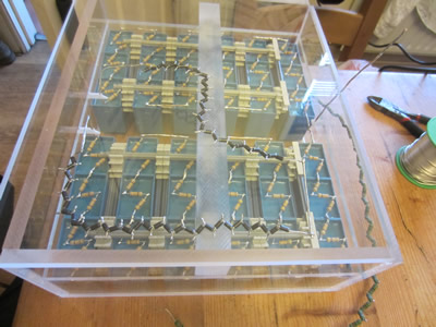
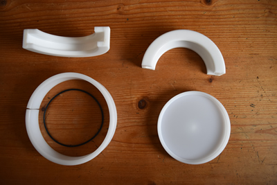
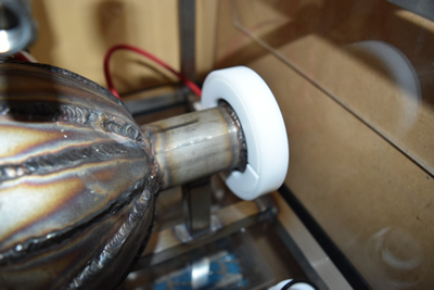
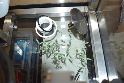
I had a quick go at making one of the wire grids out of some stainless filler rod, to no avail, they were too springy. I think that I may have to make the grids out of something a little thinner and possibly make myself a spot welder. I got round to making a cap for the inspection port, this is where I will be placing some kind of scintillation material. The cap is made from polyacetal, a general engineering grade material, a split ring retains it in place. If I'm going to use silver for neutron detection then this cap must be readily removable as the half-lives of the isotopes of silver are quite short. The last picture is what I used before, a stainless disc held on by the force of the vacuum, ignore the pile of resistors (mentioned later).
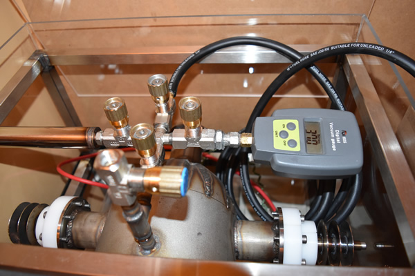
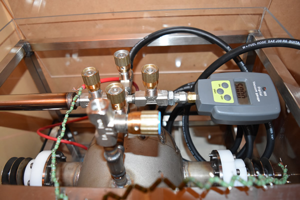
I connected up the vacuum pump and left it running for about twenty minutes, it was only to the pressure gauge with a needle valve inbetween and when the valve was closed the pressure began to increase slowly. Everything is sealed with high vacuum grease, so I'm guessing the brass may be out-gassing, I did manage to get down to 370 microns, although not the 50 microns I was aiming for. The fusor will only be run for a couple of minutes, so as long as the vacuum will hold long enough I will be happy. I left it running for about an hour, It turns out that after this amount of time I only reached a vacuum of 1750 microns, the picture shown is with the old end cap.
I realise that I need a more powerful vacuum pump, or possibly need two in series to draw a much lower vacuum. I did bid on some pumps on a internet auction site, unfortunately I lost to the seller putting shill bids with another two accounts.
I played around with the fusor by powering it up and letting an arc draw between the electrodes, I then decreased the vacuum so that the arcing would start to pulsate, I did this to test out the power supply. I managed to get the supply pulsing at 20kV until the resistor chain just fell apart (the picture earlier). When I finally have the fusor running on Argon gas it will then be time to make some deuterium gas, this is when I will have to learn some of the theory and make a prediction of the amount of neutrons produced. I'm not too concerned if my predictions are off, I just want to be only one of a handful of people in the UK public to have achieved nuclear fusion.
July 07/07/2015 - Age 22
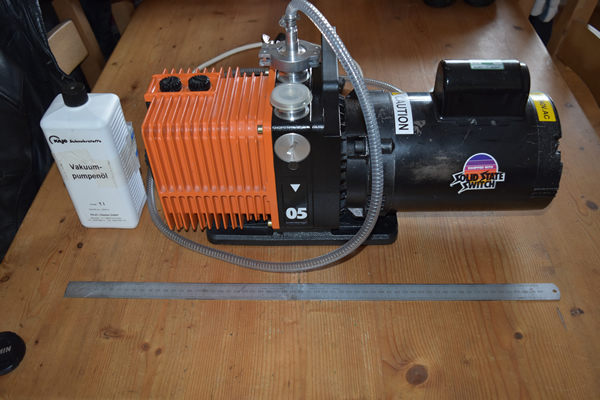 I found a suitable pump on a internet auction site, so I bought it for a total of £250, the original retail price was about £1300 and I got it through the post the next day, unfortunately I went on holiday the day after. Now I'm back off holiday I thought that it would be time to connect the vacuum pump up to the fusor, so I did and left it running for about an hour, I got it down to a measly 1300 microns, it seems that something is leaking at the fusor.
I did however test the new pump compared to my old one, the old one managed 40 microns and my new one went low enough that the gauge would not register any further, I think it's around 2 microns.
July 11/07/2015 - Age 22
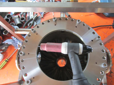
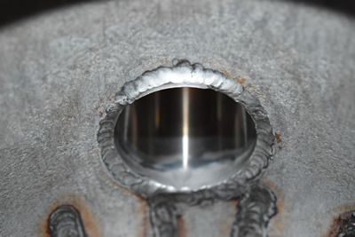
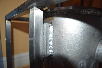
I thought that there could have been two main problems with my fusor, the welding may have been leaking and there may have been areas on the inside to trap air which lead to gassing. I first went over all of my welds on the outside, making sure I left no holes and also to make the welds a little neater. Once the outside was completed it was time to do the inside, unfortunately my TIG torch was too big to fit inside.
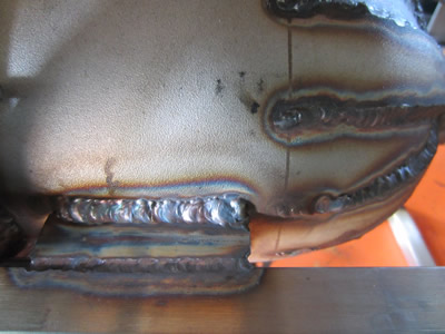
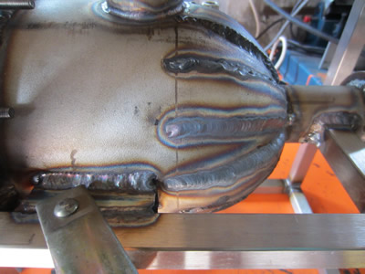
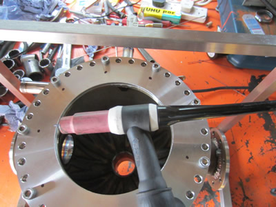
I instead decided to cut down my torch along with an electrode, I can always buy another spare part. I originally thought that I had made a mistake with allowing the steel to overlap when I made the dome, but fortunately it allowed me to weld the inside without using any kind of filler rod which otherwise would have been impossible. It took a heck of a lot of time due to me having to cool down my welding gloves every thirty seconds or so, I got there in the end.
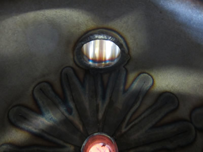
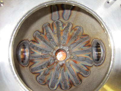
I had previously bought some acid for another project which removes the oxide coating from stainless, removing all of the brown areas. The solution is made up of nitric and fluoric acid which are extremely dangerous, so much so that it can soak through the skin and dissolve bones, and there are no restrictions to buying it. I have to admit that this stuff really makes me paranoid being around it.
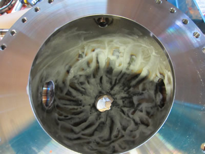
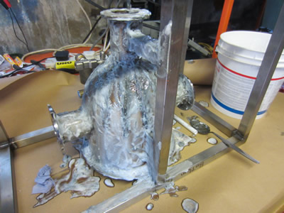
After about 20 minutes the acid had done it's job.
Hello, if you have enjoyed reading this project, have taken an interest in another or want me to progress one further then please consider donating or even sponsoring a small amount every month, for more information on why you may like to help me out then follow the sponsor link to the left. Otherwise you can donate any amount with the link below, thank you!