Inertial Confinement Fusion Page 4
November 23/11/2015 - Age 22
If there is anyone out there waiting for an update, I have been concentrating on other things at the moment but I will be finishing this project soon. Basically I can't seem to get a low enough vacuum for fusion, the only way is to "bake" out all of the moisture in the system. The whole thing is slightly too big to fit in my oven so I may have to cover the setup in a heating element and then pack it with insulation. I have bought a temperature controller that is capable of up to 120°C, I will choose this as my bake-out temperature. I now need to find some way of heating it all up, probably nichrome wire or something like that and then wrapping the whole thing in insulation.
December 04/12/2015 - Age 22
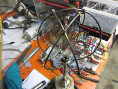
I need to get this project done, I see it every time I wake up and it bugs me that I haven't yet proved fusion. I set out to make the wire grids today out of some stainless wire, my first attempt was to TIG weld it but it proved difficult due to the springiness. The only way to remove the spring was to heat it and then allow it to slowly cool or to work it while hot. I had the great idea of using a microwave oven transformer with a small turn secondary as a high current transformer to heat the wire around an aluminium former. Due to the former bring conductive it allowed the wire to stay hot as I wound it around the former.
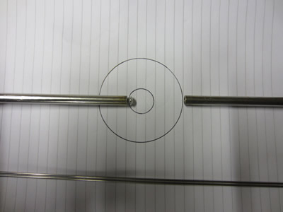
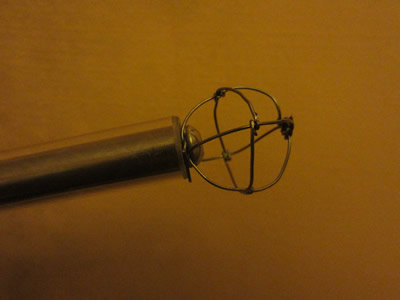
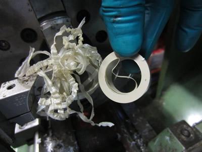
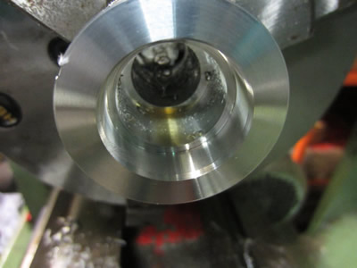
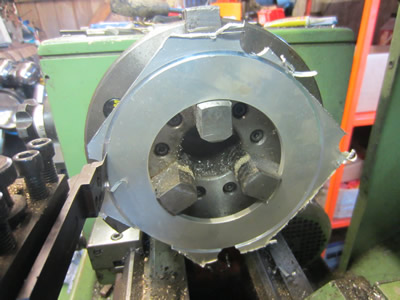
The wire was cut up into three pieces and then placed inside of an insert that I made on the lathe, I used tantalum wire to bind everything together as I had run out of gas for the TIG welder.
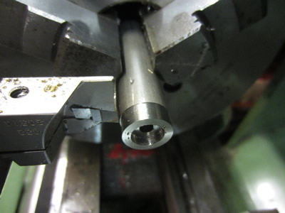
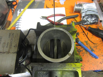
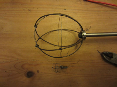
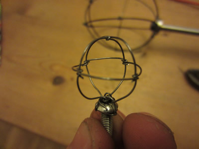
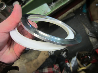
The inner sphere was made from tantalum wire, I had to modify the sphere in the second picture as it wasn't central to the larger grid when assembled in the fusor.
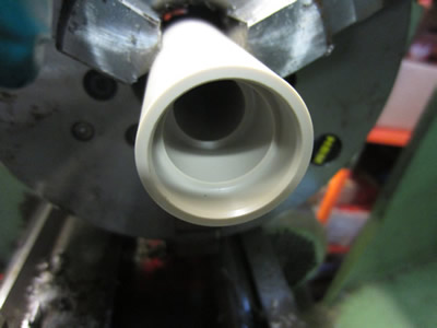
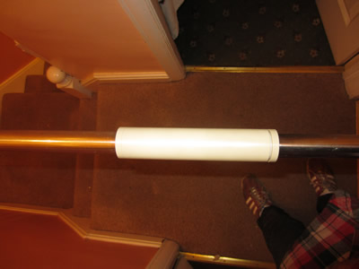
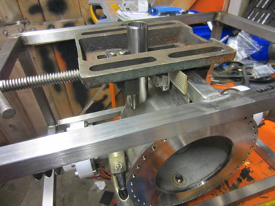
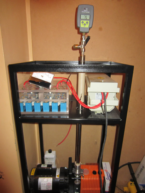
I decided to test the fusor with to see what vacuum I could get down to, the only difference from the first attempt is that the inside has been welded. Before was a maximum of 1300 microns and that was after nearly two hours, I left it for 40 minutes this time and managed 540 microns.
From having a little play around with the fusor I realised what was wrong, the pipes were too thin. I closed the main valve on the fusor only a slight amount and the pressure gauge sharply started to decrease, closing it all the way it dropped down to 50 microns. I think I will make all of the piping to be one inch stainless with a peek spacer to insulate it from the pump. It makes sense as the lower the pressure drops the less atoms are present and the flow decreases. It can be see in the opposite way, as you increase pressure flow increases, so it works the opposite way, therefore meaning orifices have to be wider to allow flow at lower pressures.
December 05/12/2015 - Age 22
I measured the vacuum port on my pump, it is known as a KF25 which has an internal diameter of 25mm. I have some stainless tube which equates to an internal diameter of 22mm. I found a pressure drop chart online, with my pump running at 3.8cfm and this internal diameter it equates to a drop of 0.28 in Hg/ 100ft. The line will be approximately 2.5 feet long which results in a drop of 178 micron. Now that may sound bad but this is only at a flow of 3.8cfm, when the flow decreases so does the pressure drop. The pump is capable of 1.5 micron, with a five foot hose with an internal bore of 6mm it managed a vacuum of 50 microns. This hose is 13.5 times smaller than the one I'm going to now use. I have bought a hole saw to cut into the fusor vessel and in a couple of days I will pick up some more gas for the TIG welder.
December 06/12/2015 - Age 22
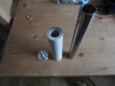
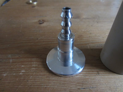
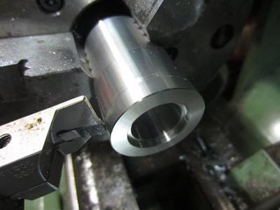
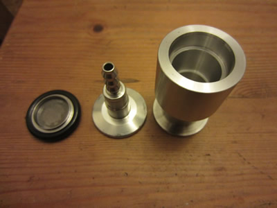
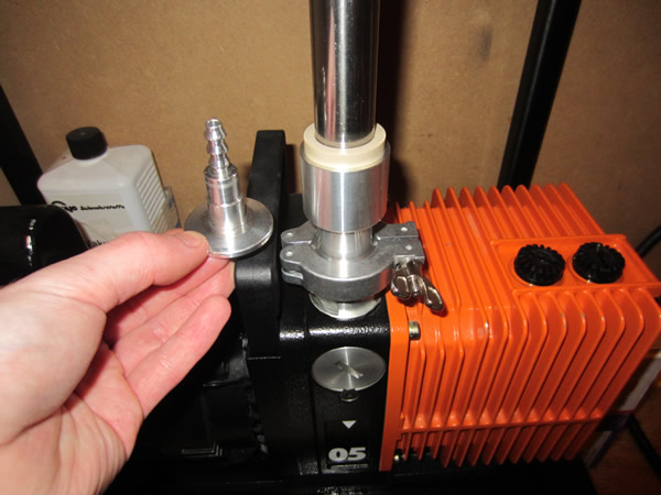
The objective of today was to make an adapting port for the vacuum pump to a piece of stainless tube, it was also to make an insulator for between the pump and the fusor. The picture in the middle is the original connector to the pump, it's flange is known as a KF25 which means that all of the dimensions are standardised and therefore available. I found out some peek tube for the insulator, stainless for the tubes and a piece of aluminium to make the new flange adapter.
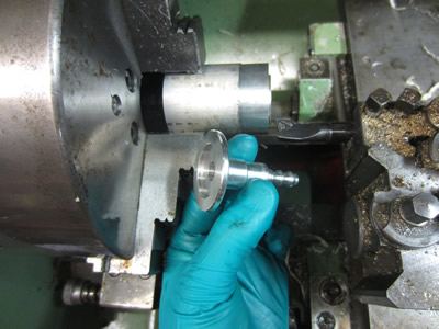
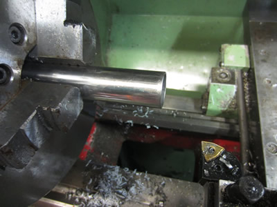
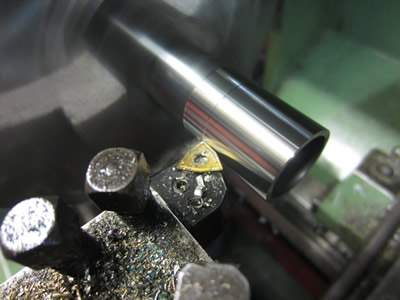
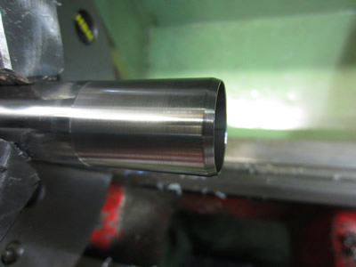
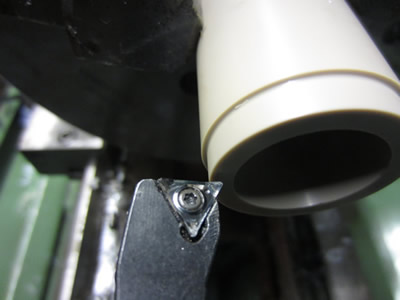
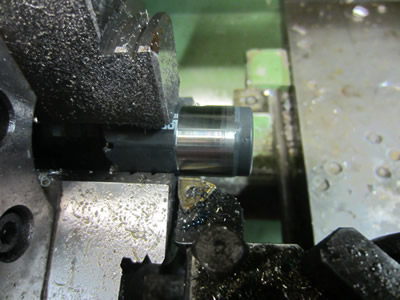
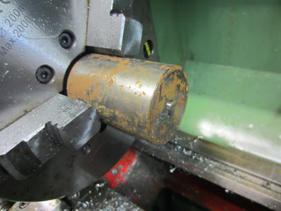
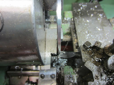
The first thing I did was turn down the ends of the stainless tube to ensure that they were round and to an exact size. A taper was machined on the end as it will be pushed through an O-ring seal. I also deburred the inside of the tube to ensure that no turnings could make their way into the pump.
I had two identical pieces of peek tube to the sizes of 35 x 22 x 150mm long. I first machined one of the tubes as an insulator, it has a bore to suit the tube, a step to suit the O-ring seal and a back-up ring type flange (if that makes sense). The second piece of tube was used to make the little back-up ring flanges, the purpose of these is to keep the O-ring level, it serves no pressure related duties. I used to machine peek at my last place of work so I knew what feeds and depths of cut I could take. It's my favorite plastic to work with but it is one of the more expensive ones, luckily I picked these up for free as the seller didn't know what it was.
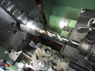
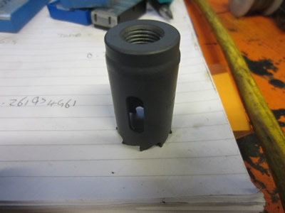
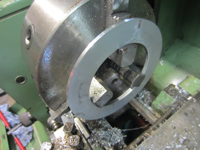
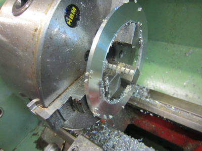
The final part to make was the flange adapter. I first started out with some aluminium bar and then drilled it out with a 1/2" drill and then a 20mm drill, the swarf came out several metres long. I then bored the centre out to the exact dimensions as to those of the peek insulator tube that I made earlier.

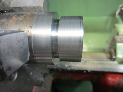
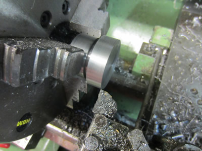
The outside was turned to exactly 40mm as that's what the sample was, then the whole thing was spun around to do the other side. I first bored it out to 22mm as this is what the stainless tubes are and then turned a step in the front that will hold a sealing ring. The next step was to use my grooving tool to take out some of the aluminium in the middle so that the flange clamp would fit. The flange has an angle on the back of it so that when the clamp is tightened it causes the flange to squash down. I measured the sample the best I could (all corners were radii), did some calculations on my phones calculator and then online which came out in radians, then back on my phone to finally get to exactly 15 degree's. What took several minutes was confirmed by a pdf I downloaded in seconds, oh well, atleast my maths skills are getting used.

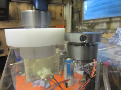
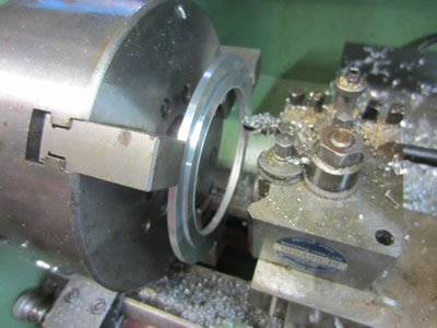
The angle came out perfect, the last job was to chamfer all of the corners with a file. The last picture shows the sequence to which the parts are to be assembled.
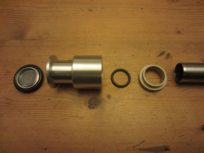
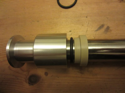
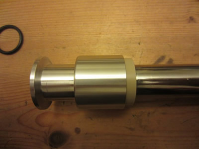
The parts assembled perfectly, all parts were machined so that there would be a 0.05mm clearance. The last picture shows the insulator tube with two stainless tubes inserted (it's quite a bad picture).
The flange was assembled on the pump, the clamp worked perfectly by pushing both of the flanges together. I will have to wait until I get the hole saw before I can progress any of the build further.
December 09/12/2015 - Age 22
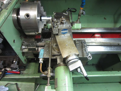
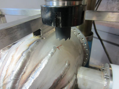
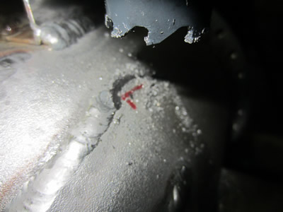
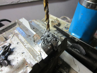
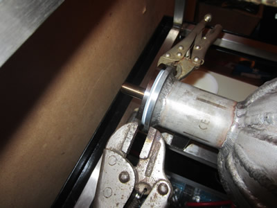
I picked up some gas and got my hole saw through the post. I was going to make an arbor but I instead turned the outside of the saw itself to make it round and stuck it in the millers collet chuck. I clamped my whole fusor setup in the miller and set the spindle speed at about 120rpm.
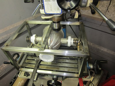
The holesaw still didn't turn true but it was better than before the saw was modified. All of this didn't help with the fact that I was cutting at an angle too but I slowly got there in the end.
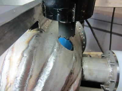
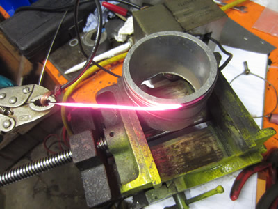
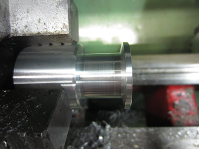
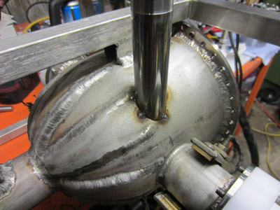
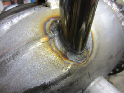
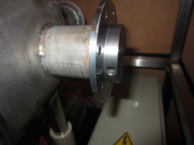
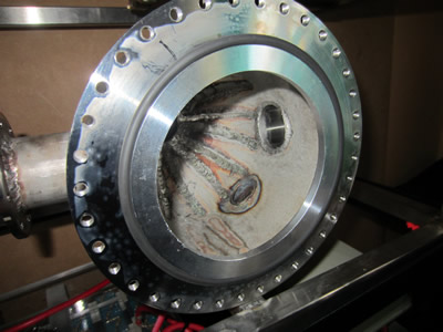
One of the stainless tubes that I turned earlier was tack welded into place and then finally welded complete.
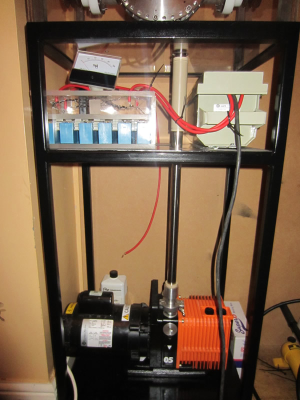
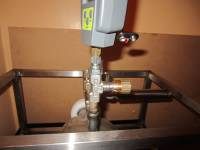
I drilled out the bottom of the perspex box along with the steel shelf so that the vacuum pipes would have somewhere to go through. I switched the vacuum pump on and waited for it to go down, it didn't, it went down to a maximum of 6000 microns which was a mile off what I was hoping. I decided to make an adapter for the vacuum gauge to fit into my peek insulator, I was hoping that it was these seals that were leaking. The vacuum went so low that it actually went below the minimum 15 microns that my gauge can read. All of this means that it must be my vessel that is leaking or the O-ring seals surrounding it. My next objective is to make some end caps out of metal that will definately seal the ports, if this doesn't work then it would be down to the welding around the window flange.
December 10/12/2015 - Age 22
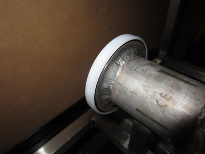
I started the day with the intention of making two end caps for the fusor as I suspected that the PTFE I used was too porous. I was going to use aluminium but I found a small billet of mild steel which was the material used. The O-rings that I used for the vacuum pipe in my last update used a compression of twenty percent so I chose this again to cut the grooves to the right dimensions. The pictures are self explanetory.
The PTFE caps were a real pain to remove so I chose to drill a hole through the steel caps so they could be easily removed with a screwdriver. I spent a bit of time scraping a lead chamfer with the deburring tool in the ports to try and prevent damaging the O-ring when installing. I managed to insert the caps by hand this time due to the lead chamfer, there was no point in bolting them down.
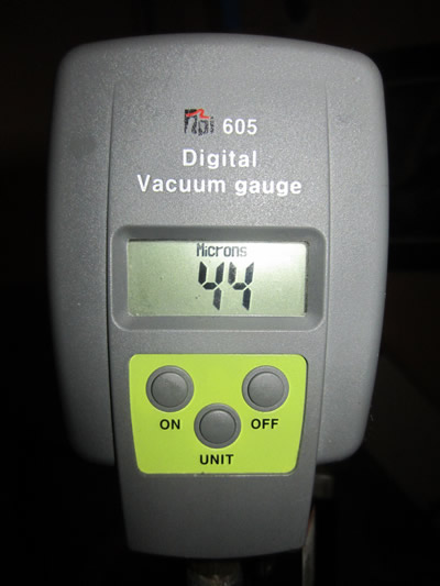
The vacuum quickly decreased down to about 60 microns and then slowly creeped down to 44 microns. I did an experiment to see if the plastic end cap was permiating any gas by clamping an O-ring between some stainless instead. The vacuum capability was even worse which means that the PTFE spacer I used must have been holding a lot of moisture, the experiment was valuable in a different way. If a spacer ring as small as this can hold so much gas then maybe the spacer ring for the viewing window may also be producing a lot of gas. From here I could probably go onto fusion but I want a better performance.
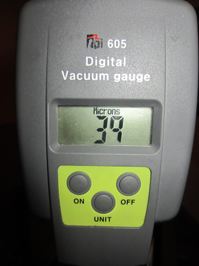
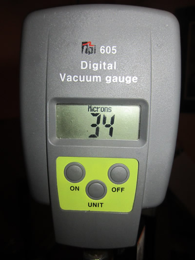
I have some stainless sheet left so I may have to make a spacer out of this to see what change in performance there will be, I'm expecting it to be quite tremendous, well I'm hoping. I can't afford to be buying any peek for the the insulators so will have to use acetal instead, the differences will be quite minute. I left the pump going for about half and hour and ended up with 34 microns, it's not far, but I should be able to go further with the changes I'm about to make.
December 11/12/2015 - Age 22
I had some aluminium sheet that was used in another project, it's no longer needed so I thought to make the spacer from this. At these kinds of vacuums the gasing effects of aluminium will be minimal, the only real problem may be the neutrons hitting the aluminium and activating it into a radioactive substance. I was originally going to use a silver coin to prove fusion but this would be rather difficult due to it's thickness, using aluminium foil will produced sodium-24 which has a half life of 15 hours and beta decays. I have a geiger counter on hand, so if I do produce anything that could harm my health then I can dispose of it.
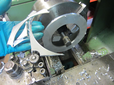
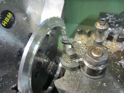
The aluminium sheet was 6mm thick and was cut into a rough square with the angle grinder. Due to the sheet already having a circular bore it allowed me to place it in the lathes chuck, I used a special grooving tool to quickly cut the outside to a circle.


I couldn't cut any more of the OD off as I was cautious of hitting the jaws, so instead I worked on the face trying to get as close down to the jaws as possible. The ring had to be run at the lathes lowest speed of 52rpm to stop the tool resonating. The ring was removed from the jaws and turned around utilising the step as a stand off from the jaws. I then worked the OD down from 155mm to the correct dimension of 141mm.
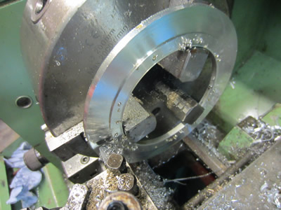
The face was then turned to get the step height to exactly 4.2mm, again only able to use 52rpm as the finish speed. I removed the ring from the jaws and deburred all of the corners, a different set of jaws where placed in the chuck to allow me to clamp down on the outside of the ring.
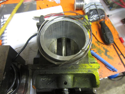
The bore was then turned to the correct diameter, all of the corners were deburred and the ring was placed in the fusor, a perfect fit. I turned the vacuum pump on expecting great results and I just ended up with the exact vacuum pressure as before, I guess that PTFE really does out gas quickly. I've never been too convinced about my vacuum gauge and believe this could be a possible cause, I do think the sensor leaks internally.
There are only two more experiments that I can do, one is to retry my gauge on the pump with all the link pipes in place except a smaller diameter tube to replicate than on the fusor, I can then see what kind of pressure drop there is, if any, and then determine what pressure I'm actually getting. The other is to place some vacuum grease to the internals of the gauge to see if that is the root problem.
I packed some vacuum grease around the sensor in the gauge and it made no difference at all.
Hello, if you have enjoyed reading this project, have taken an interest in another or want me to progress one further then please consider donating or even sponsoring a small amount every month, for more information on why you may like to help me out then follow the sponsor link to the left. Otherwise you can donate any amount with the link below, thank you!